US4934779A - System and method for low noise optical retroreflection with gain - Google Patents
System and method for low noise optical retroreflection with gain Download PDFInfo
- Publication number
- US4934779A US4934779A US07/342,007 US34200789A US4934779A US 4934779 A US4934779 A US 4934779A US 34200789 A US34200789 A US 34200789A US 4934779 A US4934779 A US 4934779A
- Authority
- US
- United States
- Prior art keywords
- probe beam
- amplified
- medium
- wave mixing
- pump
- Prior art date
- Legal status (The legal status is an assumption and is not a legal conclusion. Google has not performed a legal analysis and makes no representation as to the accuracy of the status listed.)
- Expired - Lifetime
Links
Images


Classifications
-
- G—PHYSICS
- G02—OPTICS
- G02F—OPTICAL DEVICES OR ARRANGEMENTS FOR THE CONTROL OF LIGHT BY MODIFICATION OF THE OPTICAL PROPERTIES OF THE MEDIA OF THE ELEMENTS INVOLVED THEREIN; NON-LINEAR OPTICS; FREQUENCY-CHANGING OF LIGHT; OPTICAL LOGIC ELEMENTS; OPTICAL ANALOGUE/DIGITAL CONVERTERS
- G02F1/00—Devices or arrangements for the control of the intensity, colour, phase, polarisation or direction of light arriving from an independent light source, e.g. switching, gating or modulating; Non-linear optics
- G02F1/35—Non-linear optics
- G02F1/353—Frequency conversion, i.e. wherein a light beam is generated with frequency components different from those of the incident light beams
- G02F1/3536—Four-wave interaction
- G02F1/3538—Four-wave interaction for optical phase conjugation
-
- G—PHYSICS
- G02—OPTICS
- G02B—OPTICAL ELEMENTS, SYSTEMS OR APPARATUS
- G02B5/00—Optical elements other than lenses
- G02B5/12—Reflex reflectors
- G02B5/122—Reflex reflectors cube corner, trihedral or triple reflector type
- G02B5/124—Reflex reflectors cube corner, trihedral or triple reflector type plural reflecting elements forming part of a unitary plate or sheet
-
- G—PHYSICS
- G02—OPTICS
- G02F—OPTICAL DEVICES OR ARRANGEMENTS FOR THE CONTROL OF LIGHT BY MODIFICATION OF THE OPTICAL PROPERTIES OF THE MEDIA OF THE ELEMENTS INVOLVED THEREIN; NON-LINEAR OPTICS; FREQUENCY-CHANGING OF LIGHT; OPTICAL LOGIC ELEMENTS; OPTICAL ANALOGUE/DIGITAL CONVERTERS
- G02F1/00—Devices or arrangements for the control of the intensity, colour, phase, polarisation or direction of light arriving from an independent light source, e.g. switching, gating or modulating; Non-linear optics
- G02F1/01—Devices or arrangements for the control of the intensity, colour, phase, polarisation or direction of light arriving from an independent light source, e.g. switching, gating or modulating; Non-linear optics for the control of the intensity, phase, polarisation or colour
- G02F1/03—Devices or arrangements for the control of the intensity, colour, phase, polarisation or direction of light arriving from an independent light source, e.g. switching, gating or modulating; Non-linear optics for the control of the intensity, phase, polarisation or colour based on ceramics or electro-optical crystals, e.g. exhibiting Pockels effect or Kerr effect
- G02F1/0338—Devices or arrangements for the control of the intensity, colour, phase, polarisation or direction of light arriving from an independent light source, e.g. switching, gating or modulating; Non-linear optics for the control of the intensity, phase, polarisation or colour based on ceramics or electro-optical crystals, e.g. exhibiting Pockels effect or Kerr effect structurally associated with a photoconductive layer or having photo-refractive properties
Definitions
- This invention relates to systems and methods for processing optical data, and more particular to the amplification and retroreflection of an optical information bearing beam.
- Optical amplification and retroreflection are two functions that are used in various stages in the processing of optical data.
- the two functions are incorporated together in an optical associative memory for pattern recognition, such as the systems disclosed in U.S. Pat. Nos. 4,739,496 to Marom, et al., "Associative Holographic Memory Apparatus Employing Phase Conjugate Mirrors", and 4,750,153 to Owechko, et al., "Associative Holographic Memory Apparatus Employing Phase Conjugate Mirrors and a Two-Wave Mixing Contra-Directional Coherent Image Amplifier", both assigned to Hughes Aircraft Company, the assignee of the present invention.
- Associative memories are also discussed in Dunning, et al., "All-Optical Associative Memory with Shift Invariance and Multiple-Image Recall", Optics Letters, Vol. 12, No. 5, May 1987, pages 346-348, and Soffer, et al., "Associative Holographic Memory with Feedback Using Phase-Conjugate Mirrors", Optics Letters, Vol. 11, No. 2, February, 1986, pages 118-120.
- Amplification and retroreflection functions are also combined in optical computers to amplify and redirect a two-directional array of data.
- Photorefractive materials In such materials, the index of refraction changes under the influence of applied light, such as a laser beam. The light causes charges within the photorefractive material to migrate and separate, producing an internal space charge electrostatic field. This field produces a change in the crystal's refractive index by the linear electro-optic effect (the Pockels effect).
- Photorefractive materials generally comprise BaTiO 3 , Bi 12 SiO 20 , KTa 1-x Nb x O 3 , BGO and LiNbO 3 , and III-V and II-VI semiconductor materials within the periodic table, such as, for example, GaAs and InP.
- Optical amplification without retroreflection, has been accomplished by two-wave mixing in a photorefractive crystal.
- An information bearing probe beam intersects a pump beam within the crystal. With a proper crystal orientation relative to the two beams, energy is transferred from the pump to the probe beam to amplify the latter. While ideally the probe beam would simply be amplified without any other change, in practice the photorefractive crystal will frequently impose unwanted additional phase information upon the probe beam, thus distorting its information content.
- Two-wave mixing within photorefractive materials is discussed in Laeri, et al., "Coherent CW Image Amplifier and Oscillator Using Two-Wave Interaction in a BaTiO 3 -Crystal", Optics Communications, Vol.
- High gain laser media such as metal vapors or dyes
- these systems are noisy and require an intense input to have a useful signal-to-noise ratio. This often leads to pulsed amplification, as opposed to the two-wave mixing technique which can operate continuously at flux intensities on the order of milliwatts per cm 2 .
- phase conjugation a special form of retroreflection referred to as phase conjugation has been achieved with devices known as phase conjugate mirrors (PCMs).
- PCMs phase conjugate mirrors
- a PCM produces a retroreflection of an incident beam, with the phase of the reflected beam reversed from that of the incident beam at the point of reflection.
- PCMs phase conjugate mirrors
- self-pumped PCMs those employing Brillouin or Raman scattering are generally used with high power pulsed laser beams, such as from a Nd:YAG laser, but are not practical with low power continuously operated lasers such as HeNe or low flux Argon ion laser devices.
- Another type of self-pumped PCM uses a photorefractive material with a high electro-optical coefficient as the phase conjugating medium. This type of self-pumped PCM has been employed with continuously operating, low-power lasers, but tends to produce a somewhat noisy conjugated output. After a long buildup time, the self-pumped PCMs emit a conjugated output, but do not provide amplification.
- Pseudoconjugators Another class of devices that perform retroreflection but not amplification is referred to as "pseudoconjugators”. These devices resemble PCMs in that they retroreflect incident beams. However, they do not perform a true conjugation or wavefront reversal on the incident wavefront. Pseudoconjugators have commonly been configured as arrays of corner reflectors. Such devices are discussed in articles by O'Meara, "Wavefront Compensation with Pseudoconjugation", Optical Engineering, Vol. 21, No. 2, March/April 1982, pages 271-280, and in Jacobs, "Experiments with Retrodirective Arrays", Optical Engineering, Vol. 21, No. 2, March/April 1982, pages 281-283.
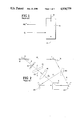
- FIG. 2(a) the use of a pseudoconjugator in a double-pass reflective conjugation compensation system is illustrated in FIG. 2(a).
- an input beam is initially transmitted through a distorting medium, and then retroreflected by a pseudoconjugator back through the distorting medium to remove the distortions.
- pseudoconjugators do achieve a retroreflection function, they are non-amplifying. Also, they include no inherent mechanism to compensate for noise in an input beam.
- a combination of both amplification and retroreflection has been achieved with the four-wave mixer PCM.
- Such a device is illustrated in simplified form in FIG. 1.
- a pair of contradirectional laser beams 2 and 4 are directed into a photorefractive mixing medium 6.
- An initializing laser beam E i equal in frequency to beams 2 and 4, is directed into the mixing medium from the side.
- a reflected beam RE i * is reflected back in a direction opposite to incident beam E i . Since power is pumped into the system by beams 2 and 4, the PCM may be configured to provide an amplification which makes R greater than 1.
- FIG. 2 A system for implementing a four-wave mixer is illustrated in FIG. 2.
- An input beam 8 is divided by a beam splitter 10 into first and second beams 12 and 13.
- Beam 12 passes through an optical mask 14, from which it acquires information.
- a portion of the beam is diverted for input monitoring by a beam splitter 15, while the remainder is focused by a lens 16 as the probe beam E i .
- the second beam 13 is reflected off a mirror 18 to a beam splitter 20, from which it emerges as pump beams 2 and 4.
- These beams are reflected off mirrors 22 and 24, respectively, and directed into the photorefractive mixing medium 6.
- the conjugated return beam is deflected by beam splitter 15 to yield an output beam 25.
- the system of FIG. 2 is fairly complex to set up, since all of the beams must interact within the same volume of the non-linear photorefractive medium 6, and careful alignment is required. While the system is illustrated for only a single beam at a single frequency, in practice beams with multiple frequencies may be used. Since pump beams must be provided with the same frequency as the probe beam for each different frequency, additional equipment and alignment complexity may be required.
- the purpose of the present invention is to provide a system and method which accomplishes both optical retroreflection and amplification, and yet avoids mechanical complexity and severe alignment problems, is broadband in operation, has a fast response, and achieves a high signal-to-noise ratio.
- the invention achieves these goals by amplifying a probe beam with a two-wave mixer, using a pseudoconjugate reflector to direct the amplified probe beam back through the two-wave mixer, and compensating within the mixer for phase distortions which were imposed on the probe beam during its initial amplifying pass.
- the pseudoconjugator may consist of a convergent lens positioned in the path of the probe beam after amplification and spaced from the non-linear photorefractive medium by its focal length, together with a flat mirror which reflects the amplified probe beam back through the lens and the non-linear medium.
- a curved mirror may be positioned in the path of the amplified probe beam, with its radius of curvature centered on the nonlinear medium.
- a non-linear medium such as barium titanate is used.
- the amplified probe beam is preferably directed back through the non-linear medium along substantially the same path as its first pass, but in the opposite direction.
- FIGS. 1 and 2 are diagrams of a known four-wave mixer and of an optical system employing such a mixer, respectively, which were described above;
- FIG. 3 is a diagram of an optical gain and retroreflection system constructed in accordance with the invention.
- FIGS. 4-6 are diagrammatic elevation views showing the operation of different types of pseudoconjugators with the invention.
- FIG. 3 One example of a system in accordance with the present invention is shown in FIG. 3.
- An input beam 26 is divided by beam splitter 28 into a relatively weak probe beam 30, and a relatively strong pump beam 32.
- the pump beam 32 is reflected off a mirror 34 into a non-linear photorefractive medium 36, such as a barium titanate crystal or any other medium suitable for two-wave mixing.
- a non-linear photorefractive medium 36 such as a barium titanate crystal or any other medium suitable for two-wave mixing.
- Probe beam 30 acquires a desired information format by transmission through a transmission mask 38, spatial light modulator, or other suitable mechanism for applying information to the beam, typically in the form of a phase and/or amplitude modulation.
- the probe beam 30 continues through a beam splitter 40, where a first portion 41 is diverted for input monitoring, and the remaining portion is then focused onto the photorefractive medium 36 by a lens 42. While it is not an essential part of the invention, focusing of the probe beam is normally done both because the input beam image is typically larger than the size of crystal 36, and because focusing increases the beam's flux within crystal 36, thereby improving the crystal's response time.
- the pump beam 32 and probe beam 30 intersect within the photorefractive crystal 36, which is oriented to produce a two-wave mixing transfer of energy from the pump to the probe beam. This is achieved by positioning crystal 36 so that its C-axis points in the direction of rotation from the pump beam direction to the probe beam direction.
- the probe beam 30 is thus amplified during its transit through crystal 36. After leaving the crystal, the amplified beam is retroreflected by a pseudoconjugator 44, which directs it back through the crystal parallel to its original amplifying pass, but in the opposite direction. The returned beam is then collimated by lens 42 and split by beam splitter 40 to yield a phase or amplitude modulated output beam 46.
- the return of the probe beam back through the photorefractive crystal 36 after it has been amplified is an important aspect of the invention.
- the photorefractive medium With an ideal two-wave mixer, the photorefractive medium will not introduce any distortions in either the phase or the amplitude information carried by the probe beam. However, in practical systems, some amount of distortion is normally introduced; changes in phase caused by the photorefractive medium result in additional degrees of divergence or convergence within the beam.
- returning the amplified probe beam back through the photorefractive medium results in a substantial removal of such distortions. Since the return beam travels in the opposite direction to the original input probe beam, there will be no appreciable energy transfer between the return beam and the pump beam.
- a corner cube array 48 provides the pseudoconjugating element.
- Probe beam 30 is illustrated as a collimated beam, but it could also be converging.
- the corner cube array 48 should be large enough and close enough to photorefractive crystal 36 to receive the entire probe beam.
- Probe beam 30 passes through crystal 36, where it is amplified by pump beam 32.
- the amplified signal propagates to the corner cube array 48.
- Each ray within the beam undergoes multiple reflections at the corner cube array, as indicated in the FIG.
- the retroreflected return rays 50 propagate closer to the paths of their respective incident rays.
- the return rays approach a smooth retroreflection of the incident signal.
- FIG. 5 Another embodiment, shown in FIG. 5, is designed particularly for a converging beam 30.
- the beam is focused into the photorefractive crystal 36, where it is amplified by pump beam 32. A crossover occurs within the crystal, so that the amplified probe beam emerges as an expanding beam 52.
- This beam is collimated by a lens 54, which is positioned at one focal length from the two-wave mixer.
- the beam then propagates parallel to the optic axis of the device, and is reflected back off a substantially flat mirror 56 which is positioned at right angles to the propagation axis.
- the light then counterpropagates back over its original path and through the photorefractive medium 36, in the opposite direction to its first pass. Again, distortions introduced by the photorefractive medium are substantially compensated during the reverse pass.
- the return beam can be diverted from the original path after it has passed back through the photorefractive medium, and its information content observed or used in further processing.
- FIG. 6 illustrates a third embodiment for a pseudoconjugator, in which the separate functions of the lens 54 and flat mirror 56 in FIG. 5 are combined in a single optical element implemented as a curved mirror 58.
- Mirror 58 has a radius of curvature which is equal to the distance between the mirror and photorefractive crystal 36, and centered upon the crystal. It can be placed at the position occupied by lens 54 in FIG. 5.
- the invention has been demonstrated in an associative memory.
- the associative memory originally employed a degenerate four-wave mixing PCM to produce optical feedback and gain.
- the PCM was replaced by a pseudoconjugate optical gain system of the type illustrated in FIG. 5.
- Two-wave mixing was accomplished in a barium titanate crystal.
- a lens with an F number equal to one was placed between the crystal and a flat mirror at one focal length (7.6 cm) from the crystal.
- Incident light was successfully amplified and retroreflected.
- An iris between the crystal and mirror which limited the number of undesired light rays collected by the lens, was required to obtain a resolution comparable to that achieved with the PCM.
- the PCM produces the exact phase conjugate of the probe beam, whereas the present invention outputs a retroreflected but not true phase conjugated beam, the PCM inherently has a somewhat higher resolution.
- the described system can produce a virtually noise-free amplification of complex two-dimensional optical images with grey scale.
- the holographic nature of the two-wave amplification can produce high resolution, exceeding a thousand lines/mm.
- the area over which this resolution is achievable ranges from several square mm to a few square cm, and is primarily limited by the area of the interaction region within the photorefractive medium.
- the amplification factor of several thousands can be obtained for intensity fluxes routinely employed in the laboratory.
- the invention is particularly useful when a fast response is desired.
- PCMs employing sodium vapor for this purpose, in which the information capacity of the probe beam is restricted because of the small angle requirement between the probe and pump beams, with the present invention there is no such restriction. There can be a significant angle between the two beams, thereby allowing the full information capacity of the probe beam to be employed.
- the pseudoconjugating elements described herein have essentially instantaneous response times; the responsivity of the system as a whole is determined by the response time of the photorefractive medium.
- the pseudoconjugating elements also have the advantage of being very broad band, and can handle a wide range of frequencies. The importance of the simplicity in the mechanical setup required by the present invention becomes even more important as more frequencies are present.
Landscapes
- Physics & Mathematics (AREA)
- Nonlinear Science (AREA)
- General Physics & Mathematics (AREA)
- Optics & Photonics (AREA)
- Chemical & Material Sciences (AREA)
- Engineering & Computer Science (AREA)
- Ceramic Engineering (AREA)
- Crystallography & Structural Chemistry (AREA)
- Optical Modulation, Optical Deflection, Nonlinear Optics, Optical Demodulation, Optical Logic Elements (AREA)
Abstract
Description
Claims (10)
Priority Applications (1)
| Application Number | Priority Date | Filing Date | Title |
|---|---|---|---|
| US07/342,007 US4934779A (en) | 1989-04-24 | 1989-04-24 | System and method for low noise optical retroreflection with gain |
Applications Claiming Priority (1)
| Application Number | Priority Date | Filing Date | Title |
|---|---|---|---|
| US07/342,007 US4934779A (en) | 1989-04-24 | 1989-04-24 | System and method for low noise optical retroreflection with gain |
Publications (1)
| Publication Number | Publication Date |
|---|---|
| US4934779A true US4934779A (en) | 1990-06-19 |
Family
ID=23339939
Family Applications (1)
| Application Number | Title | Priority Date | Filing Date |
|---|---|---|---|
| US07/342,007 Expired - Lifetime US4934779A (en) | 1989-04-24 | 1989-04-24 | System and method for low noise optical retroreflection with gain |
Country Status (1)
| Country | Link |
|---|---|
| US (1) | US4934779A (en) |
Cited By (7)
| Publication number | Priority date | Publication date | Assignee | Title |
|---|---|---|---|---|
| US5035476A (en) * | 1990-06-15 | 1991-07-30 | Hamamatsu Photonics K.K. | Confocal laser scanning transmission microscope |
| US5038359A (en) * | 1989-10-10 | 1991-08-06 | Hughes Aircraft Company | Self-pumped, optical phase conjugation method and apparatus using pseudo-conjugator to produce retroreflected seed beam |
| EP0485267A1 (en) * | 1990-11-09 | 1992-05-13 | Thomson-Csf | System for displayng images supplied by a spatial modulator with energy transfer |
| US5318143A (en) * | 1992-06-22 | 1994-06-07 | The Texas A & M University System | Method and apparatus for lane sensing for automatic vehicle steering |
| US5351250A (en) * | 1989-04-27 | 1994-09-27 | The Secretary Of State For Defence In Her Majesty's Government Of The United Kingdom Of Great Britain And Northern Ireland | Optical beam steering device |
| US5428439A (en) * | 1992-09-23 | 1995-06-27 | The Texas A&M University System | Range measurement system |
| US20100279446A1 (en) * | 2005-03-07 | 2010-11-04 | Joseph Reid Henrichs | Optical phase conjugation laser diode |
Citations (6)
| Publication number | Priority date | Publication date | Assignee | Title |
|---|---|---|---|---|
| US3865467A (en) * | 1970-08-07 | 1975-02-11 | Little Inc A | Retroreflecting beam splitter and apparatus for measuring gravity gradients embodying the same |
| US4703992A (en) * | 1986-05-27 | 1987-11-03 | Rockwell International Corporation | Laser beam cleanup by photorefractive two-way mixing |
| US4721362A (en) * | 1985-05-31 | 1988-01-26 | The United States Of America As Represented By The Secretary Of The Army | Phase gradient contrast microscope |
| US4739496A (en) * | 1985-10-11 | 1988-04-19 | Hughes Aircraft Company | Associative holographic memory apparatus employing phase conjugate mirrors |
| US4750153A (en) * | 1985-10-11 | 1988-06-07 | Hughes Aircraft Company | Associative holographic memory apparatus employing phase conjugate mirrors and a two-wave mixing contra-directional coherent image amplifier |
| US4768846A (en) * | 1986-04-24 | 1988-09-06 | The British Petroleum Co. Plc | Phase conjugate reflecting media |
-
1989
- 1989-04-24 US US07/342,007 patent/US4934779A/en not_active Expired - Lifetime
Patent Citations (6)
| Publication number | Priority date | Publication date | Assignee | Title |
|---|---|---|---|---|
| US3865467A (en) * | 1970-08-07 | 1975-02-11 | Little Inc A | Retroreflecting beam splitter and apparatus for measuring gravity gradients embodying the same |
| US4721362A (en) * | 1985-05-31 | 1988-01-26 | The United States Of America As Represented By The Secretary Of The Army | Phase gradient contrast microscope |
| US4739496A (en) * | 1985-10-11 | 1988-04-19 | Hughes Aircraft Company | Associative holographic memory apparatus employing phase conjugate mirrors |
| US4750153A (en) * | 1985-10-11 | 1988-06-07 | Hughes Aircraft Company | Associative holographic memory apparatus employing phase conjugate mirrors and a two-wave mixing contra-directional coherent image amplifier |
| US4768846A (en) * | 1986-04-24 | 1988-09-06 | The British Petroleum Co. Plc | Phase conjugate reflecting media |
| US4703992A (en) * | 1986-05-27 | 1987-11-03 | Rockwell International Corporation | Laser beam cleanup by photorefractive two-way mixing |
Non-Patent Citations (14)
| Title |
|---|
| B. H. Soffer et al, "Associative holographic memory with feedback using phase-conjugate mirrors", Optics Letts. vol. 11, Feb. 1986, pp. 118-120. |
| B. H. Soffer et al, Associative holographic memory with feedback using phase conjugate mirrors , Optics Letts. vol. 11, Feb. 1986, pp. 118 120. * |
| F. Laeri, et al, "Coherent CW image amplifier and oscillator using two-wave interaction in a BaTiO3 Crystal", Optics Communications, vol. 47 No. 6, Oct. 15, 1983, pp. 387-390. |
| F. Laeri, et al, Coherent CW image amplifier and oscillator using two wave interaction in a BaTiO 3 Crystal , Optics Communications, vol. 47 No. 6, Oct. 15, 1983, pp. 387 390. * |
| G. J. Dunning et al, "All-optical associative memory with shift invariance and multiple-image recall", Optics Letters, vol. 12, May 1987, pp. 346-348. |
| G. J. Dunning et al, All optical associative memory with shift invariance and multiple image recall , Optics Letters, vol. 12, May 1987, pp. 346 348. * |
| J. Feinberg, "Optical phase conjugation in photorefractive materials", Academic Press, 1983, pp. 417-443. |
| J. Feinberg, et al, "Photorefractive effects and light-induced charge migration in barium titanate", J. Appl. Phys. 51(3), Mar. 1980, pp. 1297-1305. |
| J. Feinberg, et al, Photorefractive effects and light induced charge migration in barium titanate , J. Appl. Phys. 51(3), Mar. 1980, pp. 1297 1305. * |
| J. Feinberg, Optical phase conjugation in photorefractive materials , Academic Press, 1983, pp. 417 443. * |
| S. F. Jacobs, "Experiments with retrodirective arrays", Optical Engineering vol. 21, No. 2, Mar./Apr. 1982, pp. 281-283. |
| S. F. Jacobs, Experiments with retrodirective arrays , Optical Engineering vol. 21, No. 2, Mar./Apr. 1982, pp. 281 283. * |
| T. R. O Meara, Wavefront compensation with pseudoconjugation , Optical Engineering, vol. 21, No. 2, Mar./Apr. 1982, pp. 271 280. * |
| T. R. O'Meara, "Wavefront compensation with pseudoconjugation", Optical Engineering, vol. 21, No. 2, Mar./Apr. 1982, pp. 271-280. |
Cited By (9)
| Publication number | Priority date | Publication date | Assignee | Title |
|---|---|---|---|---|
| US5351250A (en) * | 1989-04-27 | 1994-09-27 | The Secretary Of State For Defence In Her Majesty's Government Of The United Kingdom Of Great Britain And Northern Ireland | Optical beam steering device |
| US5038359A (en) * | 1989-10-10 | 1991-08-06 | Hughes Aircraft Company | Self-pumped, optical phase conjugation method and apparatus using pseudo-conjugator to produce retroreflected seed beam |
| US5035476A (en) * | 1990-06-15 | 1991-07-30 | Hamamatsu Photonics K.K. | Confocal laser scanning transmission microscope |
| EP0485267A1 (en) * | 1990-11-09 | 1992-05-13 | Thomson-Csf | System for displayng images supplied by a spatial modulator with energy transfer |
| FR2669126A1 (en) * | 1990-11-09 | 1992-05-15 | Thomson Csf | SYSTEM FOR VISUALIZING IMAGES PROVIDED BY A SPATIAL MODULATOR WITH ENERGY TRANSFER. |
| US5206674A (en) * | 1990-11-09 | 1993-04-27 | Thomson-Csf | System for the display of images given by a spatial modulator with transfer of energy |
| US5318143A (en) * | 1992-06-22 | 1994-06-07 | The Texas A & M University System | Method and apparatus for lane sensing for automatic vehicle steering |
| US5428439A (en) * | 1992-09-23 | 1995-06-27 | The Texas A&M University System | Range measurement system |
| US20100279446A1 (en) * | 2005-03-07 | 2010-11-04 | Joseph Reid Henrichs | Optical phase conjugation laser diode |
Similar Documents
| Publication | Publication Date | Title |
|---|---|---|
| US5038359A (en) | Self-pumped, optical phase conjugation method and apparatus using pseudo-conjugator to produce retroreflected seed beam | |
| US4761059A (en) | External beam combining of multiple lasers | |
| EP0009108B1 (en) | An improved laser having a nonlinear phase conjugating reflector | |
| US5090795A (en) | Integrated adaptive optics apparatus | |
| US4321550A (en) | Phase conjugate correction for high gain amplifier systems | |
| US4529273A (en) | Passive phase conjugate mirror | |
| US4750153A (en) | Associative holographic memory apparatus employing phase conjugate mirrors and a two-wave mixing contra-directional coherent image amplifier | |
| US4493085A (en) | Agile beam laser | |
| US4429393A (en) | Double phase-conjugate ring resonator | |
| US4762397A (en) | Optical phase conjugator with spatially resolvable thresholding utilizing liquid crystal light valve | |
| US4836629A (en) | Device to control a light beam in a wide angle field and application to a sensing device | |
| US5034627A (en) | Power laser generator with control of the direction of emission of the output beam | |
| US4508431A (en) | Photorefractive laser beamsteering device | |
| US20050259991A1 (en) | Method of establishing communication through free space between a pair of optical communication devices | |
| US4773739A (en) | Self-pumped phase conjugate mirror and method using AC-field enhanced photorefractive effect | |
| US4934779A (en) | System and method for low noise optical retroreflection with gain | |
| US5394412A (en) | Power laser with deflection | |
| US3626321A (en) | Optical scanner and method for optical scanning | |
| US4812682A (en) | Simultaneous all-optical logical operations using the third order nonlinear optical effect and a single waveguide | |
| US4794605A (en) | Method and apparatus for control of phase conjugation cells | |
| US3849740A (en) | Integrated optical and/or gate | |
| US4921335A (en) | Optical phase conjugate beam modulator and method therefor | |
| JPS6323137A (en) | Phase conjugation mirror | |
| US3902137A (en) | Electro-optic diffraction grating tuned laser | |
| US5023477A (en) | Transient energy self-pumped conjugator and method |
Legal Events
| Date | Code | Title | Description |
|---|---|---|---|
| AS | Assignment |
Owner name: HUGHES AIRCRAFT COMPANY, A DE. CORP., CALIFORNIA Free format text: ASSIGNMENT OF ASSIGNORS INTEREST.;ASSIGNOR:DUNNING, GILMORE J.;REEL/FRAME:005072/0223 Effective date: 19890418 |
|
| STCF | Information on status: patent grant |
Free format text: PATENTED CASE |
|
| FPAY | Fee payment |
Year of fee payment: 4 |
|
| FPAY | Fee payment |
Year of fee payment: 8 |
|
| SULP | Surcharge for late payment | ||
| AS | Assignment |
Owner name: HUGHES ELECTRONICS CORPORATION, CALIFORNIA Free format text: ASSIGNMENT OF ASSIGNORS INTEREST;ASSIGNOR:HE HOLDINGS INC., HUGHES ELECTRONICS FORMERLY KNOWN AS HUGHES AIRCRAFT COMPANY;REEL/FRAME:009350/0366 Effective date: 19971217 |
|
| FEPP | Fee payment procedure |
Free format text: PAYER NUMBER DE-ASSIGNED (ORIGINAL EVENT CODE: RMPN); ENTITY STATUS OF PATENT OWNER: LARGE ENTITY Free format text: PAYOR NUMBER ASSIGNED (ORIGINAL EVENT CODE: ASPN); ENTITY STATUS OF PATENT OWNER: LARGE ENTITY |
|
| FPAY | Fee payment |
Year of fee payment: 12 |
|
| REMI | Maintenance fee reminder mailed |