US4909892A - Apparatus for welding thermoplastic frame members - Google Patents
Apparatus for welding thermoplastic frame members Download PDFInfo
- Publication number
- US4909892A US4909892A US07/286,999 US28699988A US4909892A US 4909892 A US4909892 A US 4909892A US 28699988 A US28699988 A US 28699988A US 4909892 A US4909892 A US 4909892A
- Authority
- US
- United States
- Prior art keywords
- frame elements
- pair
- thermoplastic frame
- elements
- thermoplastic
- Prior art date
- Legal status (The legal status is an assumption and is not a legal conclusion. Google has not performed a legal analysis and makes no representation as to the accuracy of the status listed.)
- Expired - Fee Related
Links
Images


Classifications
-
- B—PERFORMING OPERATIONS; TRANSPORTING
- B29—WORKING OF PLASTICS; WORKING OF SUBSTANCES IN A PLASTIC STATE IN GENERAL
- B29C—SHAPING OR JOINING OF PLASTICS; SHAPING OF MATERIAL IN A PLASTIC STATE, NOT OTHERWISE PROVIDED FOR; AFTER-TREATMENT OF THE SHAPED PRODUCTS, e.g. REPAIRING
- B29C65/00—Joining or sealing of preformed parts, e.g. welding of plastics materials; Apparatus therefor
- B29C65/02—Joining or sealing of preformed parts, e.g. welding of plastics materials; Apparatus therefor by heating, with or without pressure
- B29C65/18—Joining or sealing of preformed parts, e.g. welding of plastics materials; Apparatus therefor by heating, with or without pressure using heated tools
- B29C65/20—Joining or sealing of preformed parts, e.g. welding of plastics materials; Apparatus therefor by heating, with or without pressure using heated tools with direct contact, e.g. using "mirror"
- B29C65/2007—Joining or sealing of preformed parts, e.g. welding of plastics materials; Apparatus therefor by heating, with or without pressure using heated tools with direct contact, e.g. using "mirror" characterised by the type of welding mirror
- B29C65/203—Joining or sealing of preformed parts, e.g. welding of plastics materials; Apparatus therefor by heating, with or without pressure using heated tools with direct contact, e.g. using "mirror" characterised by the type of welding mirror being several single mirrors, e.g. not mounted on the same tool
-
- B—PERFORMING OPERATIONS; TRANSPORTING
- B25—HAND TOOLS; PORTABLE POWER-DRIVEN TOOLS; MANIPULATORS
- B25B—TOOLS OR BENCH DEVICES NOT OTHERWISE PROVIDED FOR, FOR FASTENING, CONNECTING, DISENGAGING OR HOLDING
- B25B11/00—Work holders not covered by any preceding group in the subclass, e.g. magnetic work holders, vacuum work holders
- B25B11/02—Assembly jigs
-
- B—PERFORMING OPERATIONS; TRANSPORTING
- B25—HAND TOOLS; PORTABLE POWER-DRIVEN TOOLS; MANIPULATORS
- B25B—TOOLS OR BENCH DEVICES NOT OTHERWISE PROVIDED FOR, FOR FASTENING, CONNECTING, DISENGAGING OR HOLDING
- B25B5/00—Clamps
- B25B5/14—Clamps for work of special profile
- B25B5/142—Clamps for work of special profile for windows and frames
-
- B—PERFORMING OPERATIONS; TRANSPORTING
- B29—WORKING OF PLASTICS; WORKING OF SUBSTANCES IN A PLASTIC STATE IN GENERAL
- B29C—SHAPING OR JOINING OF PLASTICS; SHAPING OF MATERIAL IN A PLASTIC STATE, NOT OTHERWISE PROVIDED FOR; AFTER-TREATMENT OF THE SHAPED PRODUCTS, e.g. REPAIRING
- B29C65/00—Joining or sealing of preformed parts, e.g. welding of plastics materials; Apparatus therefor
- B29C65/78—Means for handling the parts to be joined, e.g. for making containers or hollow articles, e.g. means for handling sheets, plates, web-like materials, tubular articles, hollow articles or elements to be joined therewith; Means for discharging the joined articles from the joining apparatus
- B29C65/7841—Holding or clamping means for handling purposes
-
- B—PERFORMING OPERATIONS; TRANSPORTING
- B29—WORKING OF PLASTICS; WORKING OF SUBSTANCES IN A PLASTIC STATE IN GENERAL
- B29C—SHAPING OR JOINING OF PLASTICS; SHAPING OF MATERIAL IN A PLASTIC STATE, NOT OTHERWISE PROVIDED FOR; AFTER-TREATMENT OF THE SHAPED PRODUCTS, e.g. REPAIRING
- B29C66/00—General aspects of processes or apparatus for joining preformed parts
- B29C66/01—General aspects dealing with the joint area or with the area to be joined
- B29C66/05—Particular design of joint configurations
- B29C66/10—Particular design of joint configurations particular design of the joint cross-sections
- B29C66/11—Joint cross-sections comprising a single joint-segment, i.e. one of the parts to be joined comprising a single joint-segment in the joint cross-section
- B29C66/116—Single bevelled joints, i.e. one of the parts to be joined being bevelled in the joint area
- B29C66/1162—Single bevel to bevel joints, e.g. mitre joints
-
- B—PERFORMING OPERATIONS; TRANSPORTING
- B29—WORKING OF PLASTICS; WORKING OF SUBSTANCES IN A PLASTIC STATE IN GENERAL
- B29C—SHAPING OR JOINING OF PLASTICS; SHAPING OF MATERIAL IN A PLASTIC STATE, NOT OTHERWISE PROVIDED FOR; AFTER-TREATMENT OF THE SHAPED PRODUCTS, e.g. REPAIRING
- B29C66/00—General aspects of processes or apparatus for joining preformed parts
- B29C66/50—General aspects of joining tubular articles; General aspects of joining long products, i.e. bars or profiled elements; General aspects of joining single elements to tubular articles, hollow articles or bars; General aspects of joining several hollow-preforms to form hollow or tubular articles
- B29C66/51—Joining tubular articles, profiled elements or bars; Joining single elements to tubular articles, hollow articles or bars; Joining several hollow-preforms to form hollow or tubular articles
- B29C66/52—Joining tubular articles, bars or profiled elements
- B29C66/524—Joining profiled elements
- B29C66/5243—Joining profiled elements for forming corner connections, e.g. for making window frames or V-shaped pieces
- B29C66/52431—Joining profiled elements for forming corner connections, e.g. for making window frames or V-shaped pieces with a right angle, e.g. for making L-shaped pieces
-
- B—PERFORMING OPERATIONS; TRANSPORTING
- B29—WORKING OF PLASTICS; WORKING OF SUBSTANCES IN A PLASTIC STATE IN GENERAL
- B29C—SHAPING OR JOINING OF PLASTICS; SHAPING OF MATERIAL IN A PLASTIC STATE, NOT OTHERWISE PROVIDED FOR; AFTER-TREATMENT OF THE SHAPED PRODUCTS, e.g. REPAIRING
- B29C66/00—General aspects of processes or apparatus for joining preformed parts
- B29C66/70—General aspects of processes or apparatus for joining preformed parts characterised by the composition, physical properties or the structure of the material of the parts to be joined; Joining with non-plastics material
- B29C66/73—General aspects of processes or apparatus for joining preformed parts characterised by the composition, physical properties or the structure of the material of the parts to be joined; Joining with non-plastics material characterised by the intensive physical properties of the material of the parts to be joined, by the optical properties of the material of the parts to be joined, by the extensive physical properties of the parts to be joined, by the state of the material of the parts to be joined or by the material of the parts to be joined being a thermoplastic or a thermoset
- B29C66/739—General aspects of processes or apparatus for joining preformed parts characterised by the composition, physical properties or the structure of the material of the parts to be joined; Joining with non-plastics material characterised by the intensive physical properties of the material of the parts to be joined, by the optical properties of the material of the parts to be joined, by the extensive physical properties of the parts to be joined, by the state of the material of the parts to be joined or by the material of the parts to be joined being a thermoplastic or a thermoset characterised by the material of the parts to be joined being a thermoplastic or a thermoset
- B29C66/7392—General aspects of processes or apparatus for joining preformed parts characterised by the composition, physical properties or the structure of the material of the parts to be joined; Joining with non-plastics material characterised by the intensive physical properties of the material of the parts to be joined, by the optical properties of the material of the parts to be joined, by the extensive physical properties of the parts to be joined, by the state of the material of the parts to be joined or by the material of the parts to be joined being a thermoplastic or a thermoset characterised by the material of the parts to be joined being a thermoplastic or a thermoset characterised by the material of at least one of the parts being a thermoplastic
- B29C66/73921—General aspects of processes or apparatus for joining preformed parts characterised by the composition, physical properties or the structure of the material of the parts to be joined; Joining with non-plastics material characterised by the intensive physical properties of the material of the parts to be joined, by the optical properties of the material of the parts to be joined, by the extensive physical properties of the parts to be joined, by the state of the material of the parts to be joined or by the material of the parts to be joined being a thermoplastic or a thermoset characterised by the material of the parts to be joined being a thermoplastic or a thermoset characterised by the material of at least one of the parts being a thermoplastic characterised by the materials of both parts being thermoplastics
-
- B—PERFORMING OPERATIONS; TRANSPORTING
- B29—WORKING OF PLASTICS; WORKING OF SUBSTANCES IN A PLASTIC STATE IN GENERAL
- B29C—SHAPING OR JOINING OF PLASTICS; SHAPING OF MATERIAL IN A PLASTIC STATE, NOT OTHERWISE PROVIDED FOR; AFTER-TREATMENT OF THE SHAPED PRODUCTS, e.g. REPAIRING
- B29C66/00—General aspects of processes or apparatus for joining preformed parts
- B29C66/80—General aspects of machine operations or constructions and parts thereof
- B29C66/84—Specific machine types or machines suitable for specific applications
- B29C66/843—Machines for making separate joints at the same time in different planes; Machines for making separate joints at the same time mounted in parallel or in series
-
- B—PERFORMING OPERATIONS; TRANSPORTING
- B29—WORKING OF PLASTICS; WORKING OF SUBSTANCES IN A PLASTIC STATE IN GENERAL
- B29C—SHAPING OR JOINING OF PLASTICS; SHAPING OF MATERIAL IN A PLASTIC STATE, NOT OTHERWISE PROVIDED FOR; AFTER-TREATMENT OF THE SHAPED PRODUCTS, e.g. REPAIRING
- B29C66/00—General aspects of processes or apparatus for joining preformed parts
- B29C66/80—General aspects of machine operations or constructions and parts thereof
- B29C66/84—Specific machine types or machines suitable for specific applications
- B29C66/865—Independently movable welding apparatus, e.g. on wheels
- B29C66/8652—Independently movable welding apparatus, e.g. on wheels being pushed by hand or being self-propelling
- B29C66/86531—Independently movable welding apparatus, e.g. on wheels being pushed by hand or being self-propelling being guided
- B29C66/86533—Independently movable welding apparatus, e.g. on wheels being pushed by hand or being self-propelling being guided by rails
-
- B—PERFORMING OPERATIONS; TRANSPORTING
- B29—WORKING OF PLASTICS; WORKING OF SUBSTANCES IN A PLASTIC STATE IN GENERAL
- B29C—SHAPING OR JOINING OF PLASTICS; SHAPING OF MATERIAL IN A PLASTIC STATE, NOT OTHERWISE PROVIDED FOR; AFTER-TREATMENT OF THE SHAPED PRODUCTS, e.g. REPAIRING
- B29C66/00—General aspects of processes or apparatus for joining preformed parts
- B29C66/70—General aspects of processes or apparatus for joining preformed parts characterised by the composition, physical properties or the structure of the material of the parts to be joined; Joining with non-plastics material
- B29C66/71—General aspects of processes or apparatus for joining preformed parts characterised by the composition, physical properties or the structure of the material of the parts to be joined; Joining with non-plastics material characterised by the composition of the plastics material of the parts to be joined
-
- B—PERFORMING OPERATIONS; TRANSPORTING
- B29—WORKING OF PLASTICS; WORKING OF SUBSTANCES IN A PLASTIC STATE IN GENERAL
- B29L—INDEXING SCHEME ASSOCIATED WITH SUBCLASS B29C, RELATING TO PARTICULAR ARTICLES
- B29L2031/00—Other particular articles
- B29L2031/001—Profiled members, e.g. beams, sections
- B29L2031/003—Profiled members, e.g. beams, sections having a profiled transverse cross-section
- B29L2031/005—Profiled members, e.g. beams, sections having a profiled transverse cross-section for making window frames
-
- Y—GENERAL TAGGING OF NEW TECHNOLOGICAL DEVELOPMENTS; GENERAL TAGGING OF CROSS-SECTIONAL TECHNOLOGIES SPANNING OVER SEVERAL SECTIONS OF THE IPC; TECHNICAL SUBJECTS COVERED BY FORMER USPC CROSS-REFERENCE ART COLLECTIONS [XRACs] AND DIGESTS
- Y10—TECHNICAL SUBJECTS COVERED BY FORMER USPC
- Y10T—TECHNICAL SUBJECTS COVERED BY FORMER US CLASSIFICATION
- Y10T156/00—Adhesive bonding and miscellaneous chemical manufacture
- Y10T156/17—Surface bonding means and/or assemblymeans with work feeding or handling means
- Y10T156/1702—For plural parts or plural areas of single part
- Y10T156/1744—Means bringing discrete articles into assembled relationship
- Y10T156/1746—Plural lines and/or separate means assembling separate sandwiches
-
- Y—GENERAL TAGGING OF NEW TECHNOLOGICAL DEVELOPMENTS; GENERAL TAGGING OF CROSS-SECTIONAL TECHNOLOGIES SPANNING OVER SEVERAL SECTIONS OF THE IPC; TECHNICAL SUBJECTS COVERED BY FORMER USPC CROSS-REFERENCE ART COLLECTIONS [XRACs] AND DIGESTS
- Y10—TECHNICAL SUBJECTS COVERED BY FORMER USPC
- Y10T—TECHNICAL SUBJECTS COVERED BY FORMER US CLASSIFICATION
- Y10T29/00—Metal working
- Y10T29/53—Means to assemble or disassemble
- Y10T29/53978—Means to assemble or disassemble including means to relatively position plural work parts
Definitions
- the present invention relates to apparatus for joining thermoplastic frame elements. More particularly the present invention relates to welding machines for welding corners or joints of frames such as window and door frames.
- the frame elements i.e. stiles and rails
- the frame elements when made out of wood, were secured by either an adhesive, nails, screws or some other connector, or a combination of two or more of the holding or connector components.
- metals were used for the frame elements, the pairs of frame elements were connected and held together by welding, screwing or crimping the corners together.
- window frames and door frames have been made from plastic elements.
- light weight simple jigs may be used to support and hold adjacent elements of the frames in position to be welded.
- the present invention is directed to an apparatus for welding thermoplastic frame elements to each other.
- the apparatus includes means for supporting first and second pairs of frame elements such that said pairs are oriented at a selected angle (e.g. perpendicular) with respect to each other, means for separating the frame elements constituting each pair by a selected distance, means for urging the pairs of frame elements towards each other, and means for welding the respective end portion of each pair of frame element to each other to form a joint or corner.
- a jig assembly for handling frame elements of different sizes or lengths.
- the jig assembly includes a base element, a top element, and a middle element positioned between the top and base elements. Means are provided for moving the middle and base elements towards and away from each other and for moving the middle and top elements towards or away from each other.
- the middle element may be connected by a spring to either the base or top elements such that it "floats" therebetween.
- FIG. 1 is a representation, in plan view, of a frame element retaining apparatus
- FIG. 2 is a representation in side view, of a frame welding apparatus in accordance with the invention.
- FIG. 2a is a perspective view of a portion of a rail assembly upon which a jig assembly is mounted;
- FIG. 3 represents in more detail a preferred embodiment of a jig assembly for holding multiple frame elements, in relaxed position
- FIG. 3a represents the jig assembly of FIG. 3 in closed or clamped position
- FIGS. 4, 4a and 4b are schematic illustrations of pairs of frame elements as positioned by one or more jig assemblies
- FIG. 5 is a top plan view of one corner of the frame element arrangement shown in FIG. 4(b);
- FIGS. 6-11 are schematic illustrations of various assemblies for mounting thermoplastic frames to a welding apparatus
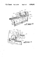
- FIG. 12 is a front perspective view of a frame welding assembly
- FIG. 13 is a front perspective view of a left hand welding station.
- a frame element welding apparatus which, in accordance with the invention, may be used as an eight point apparatus for simultaneously joining of stacked pairs of frame elements.
- Four jig assemblies 12-12c are mounted to the upper surface of the apparatus, each of which may secure two or more frame elements.
- Four pneumatic cylinders are provided, each of which includes a piston rod coupled to one of the jigs for moving the jig toward and away from the center of the table.
- Each jig is represented as having two runners which ride on rails secured to the under structure of the table.
- thermoplastic frame elements are not illustrated or represented in FIG. 1. Such plates are used to heat the angled ends of the frame elements together prior to fusing them to form the welded corners of one or more frames.
- a table 10 supports the runners or rails, the jig assemblies and the pneumatic positioning cylinders.
- the jig assemblies 12, 12a, 12b and 12c are each mounted on runners which are more clearly illustrated in FIGS. 2 and 2a.
- Each runner 14 rides on rail 15, the runner being coupled to the base element 16 of the jig 12.
- the positioning cylinders are preferably pneumatic and preferably have bi-direction control as seen at cylinder 18 of FIG. 1.
- the piston rods 19 are connected to the respective base elements 16 of the jig assemblies and drive the jig assemblies reciprocally with respect to the center of the table 10.
- the jig assemblies With frame elements clamped into the jig assemblies, the jig assemblies may be moved so that the ends of the frame elements come together to form corners, such as seen in FIGS. 4, 4a and 4b. These ends are heated by the heating plate and then joined. Upon cooling, the frame elements are welded together in a substantially perpendicular configuration.
- FIG. 2 represents in more detail the jig assembly 12 and its coupling, via the runner 14 to the rail 15 so that the piston rod 19 may drive the jig assembly inward along the rail 15 by air pressure applied through hose 21 while hose 22 is open.
- the jig may be driven outwardly with respect to the center of the table 10, by applying air pressure through hose 22 while opening hose 21.
- Thermoplastic frame elements 25 and 26 are shown in FIG. 1 within jig assemblies 12 and 12a.
- jigs 12 and 12a When the jigs 12 and 12a are positioned so that the angled ends of the frame elements 25 and 26 are adjacent, these ends are pressed against a heating plate 40 as shown in FIG. 5 for an appropriate length of time. The plate is withdrawn and the jig assemblies are again moved to press the ends against each other, thereby allowing fusion to occur.
- the base element 16 of the jig assembly 12 is coupled to the piston rod 19 so that the jig assembly 12 may be positioned along the rail 15.
- Jig assembly 12 includes the base element 16, a floating element 28 add a clamp element 30.
- Floating element 28 serves as a clamp element for the base element 16 and also serve as a base element for the clamp element 30.
- the clamp element 30 is coupled to the clamp cylinder 32 which travels in a perpendicular direction relative to the surface of the table 10.
- FIG. 3 represents the multi-element dual clamp in open position.
- FIG. 3a represents the multi-element dual clamp in closed position.
- a pneumatic cylinder 32 is mounted so as to follow the jig assembly 12 when the jig assembly is moved by the positioning cylinder 18.
- the dual purpose floating element 28 is loosely connected to the base element 16 by the spring-pin network 35, 36 and 37.
- the pins 36 and 37 are driven into the respective elements 16 and 28 passing through the spring 35. These serve to hold the floating element 28 in normal open position and permit the clamping action when the clamp element forces the floating element into a clamp position on the base element, essentially converting the floating element into a base element with respect to the top clamp element 30.
- a piston 31 extending from cylinder 32 moves the clamp element into closed (FIG. 3a) and open (FIG. 3) positions
- the shoulder 33 of the base element 16 ensures that the frame elements 25 and 25a will be in vertical alignment while the thickness of the lip 34 ensures the frame elements will be separated, assuming, that is, that the frame elements are straight.
- FIGS. 4a and 4b and 5 represent eight point, four point and four point welding positions respectively.
- four heating plates (not shown) would be used to heat the ends of each frame member 25, 25a, 26, 26a, 25', 26', 55a', 26a' so that they can be fused to the adjacent frame members.
- Two complete frames, each having four corners, are therefore formed simultaneously.
- two corners of each of two frames are heated and then joined together.
- the jig assembly grasp and secure stacked frame elements close to the ends to be welded with short, predetermined lengths of the ends exposed.
- the length of the ends exposed may vary.
- a pair of jig assemblies would accommodate frame elements as short as one foot as well as those elements longer in length, depending on the size of the table and the distance jig assemblies of the same pair may be separated. Pairs of jig assemblies are preferably adjustable, relative to the spacing between them so as to accommodate different length frame elements, without changing jigs.
- FIGS. 6-11 illustrate various alternative embodiments of the invention for securing pairs of frame elements so that stacked and spaced pairs of such elements can be heated at the ends thereof and then fused to an adjoining pair.
- one of a pair of jig assemblies 12D which includes a base element 16D including an abutment 33D, a "floating" element 34D supported by a coil spring 35D, and a top clamp assembly 30D.
- the spring 35D is supported by a column 42D mounted to the base element 16D and extending through the middle, floating element 34D. Movement of the clamp assembly downwardly causes the upper frame element 50 to be secured between the clamp assembly and the floating element. Further downward movement of the clamp assembly results in the clamping of a lower frame element 16D.
- the abutments 33D maintain each frame element in vertical alignment.
- a pair of jig assemblies as shown in the Figures are moved towards each other to join pairs of frame elements at right angles to each other.
- FIG. 7 illustrates a jig assembly 12E similar to that shown in FIG. 6.
- the base element 16E has a C-shaped configuration which allows the floating element 34E to be suspended from the top portion thereof by a coil spring 35E. The spring is held in position by a column 42E. Once the frame elements are clamped in place upon lowering of the top clamp assembly 30E, the heating plate 40 is moved to a position adjacent to the ends of the frame elements to commence the "burn-off" and fusion cycles. Abutments 33E insure that the frame elements are properly aligned on the floating and base elements.
- FIG. 8 illustrates a jig assembly 12F including a fixed middle element 34F and a resiliently supported base element 16F.
- the middle element is supported by an L-shaped mounting structure 60F.
- Abutments 33F are provided to vertically align two frame elements 50,52.
- the two clamp assemblies 30F, 30F' may be actuated to secure or release the frame elements as the base element 16F is urged towards or away from the middle element 34F.
- FIG. 9 one of a pair of adjoining jig assemblies 12G is shown in the "open" position.
- the assembly includes an L-shaped base element 16G having a fixed projection 34G extending therefrom.
- a pair of clamp assemblies 30G, 30G' are employed for securing frame elements 50G and 52. Abutments 33G insure that the frame elements are properly aligned.
- FIG. 10 includes a fixed middle element 34H an "floating" top 62H and base 16H elements supported by springs 35H, 35H'.
- the springs are mounted to a substantially vertically extending rod 42H.
- a pair of clamp assemblies 30H, 30H' are provide for securing the thermoplastic frame elements 50, 52 prior to commencement of the welding process.
- Abutments 33H maintain the frame elements in vertical alignment so they may be fused to a second pair of such elements at a ninety degree angle.
- a T-shaped support 60H supports all of the above elements except for the clamp assemblies.
- FIG. 11 illustrates another embodiment of the invention including a T-shaped support 60I defining a fixed middle element 34I.
- a threaded rod 42I extends through the middle element and supports an upper clamping element 62I and a base element 16I.
- the rod includes right handed threads between the middle and upper elements and left handed threads between the middle and base elements.
- the upper and base elements are urged towards or away from the thermoplastic frame elements 50, 52, thereby causing them to be clamped or released by the middle, upper and base elements.
- FIG. 12 illustrates left and right hand welding stations 100, 102 which are slidably mounted upon a set of tracks 104.
- a control module station 106 for controlling the welding stations is also mounted upon the tracks.
- the entire assembly is mounted to a support 108.
- thermoplastic (PVC) frame elements 50, 52, 50A, 52A, 50B, 52B are mounted to the welding assembly.
- the fixture for clamping the frame elements within each welding station shown in FIGS. 12 and 13 is omitted to provide greater clarity.
- the frame elements are omitted from FIG. 13 for the same purpose.
- the station includes a retractable, spring mounted heater plate 110 which is positioned between a pair of base plates 112, 114.
- a pair of knives (not shown) are positioned, respectively, between the base plates and heater plate for controlling the bead which is formed when the frame elements are "burned off" at their end and later fused.
- Fence plates 116 define two sides of the welding area.
- Limiters 118 are mounted near the top of the welding area and provide heat to the frame elements, thereby reducing the temperature gradients therein during the welding process.
- a pair of rig assemblies such as shown in FIG. 6 and designated by numeral 12D, are mounted, respectively, to each of the base plates 112, 114 of the welding station 100.
- the rig assemblies are magnetically coupled to the respective fence plates 116.
- Base plate 112 remains stationary during the welding process while base plate 114, and the rig assembly mounted thereto, is slidable towards and away from the heater plate 110.
- frame elements 50A, 52A are urged towards the heating plate 110 as the base plate 112 slides under the force of a pneumatic cylinder (not shown).
- the heater plate As the frame elements 50A, 52A contact the heater plate, the heater plate is urged towards the second pair of frame elements 50, 52 in the welding station 100, eventually contacting them and causing a selected length thereof to be burned off.
- the base plate 112 and rig assembly mounted thereto again slides in the direction of second pair of frame elements, causing the ends of the respective pairs of frame elements to be pressed against each other.
- the frame elements Upon cooling, the frame elements will be fixed at a ninety degree angle.
Landscapes
- Engineering & Computer Science (AREA)
- Mechanical Engineering (AREA)
- Lining Or Joining Of Plastics Or The Like (AREA)
Abstract
An apparatus for simultaneously welding two or more pairs of thermoplastic frame elements is disclosed. The apparatus includes a clamp or jig assembly which maintains the frame elements in alignment with respect to each other and to a heating plate. A driving assembly is provided for moving the frame elements towards the heating plate and/or towards each other for heating and fusion.
Description
This application is a continuation-in-part of application Ser. No. 54,792 filed May 27, 1987, now U.S. Pat. No. 4,828,239.
(1) Field of the Invention.
The present invention relates to apparatus for joining thermoplastic frame elements. More particularly the present invention relates to welding machines for welding corners or joints of frames such as window and door frames.
(2) Brief Description of the Prior Art.
Prior to the use of plastics in the manufacture of window and door frames, both wood and metal were used for making such frames. The frame elements (i.e. stiles and rails), when made out of wood, were secured by either an adhesive, nails, screws or some other connector, or a combination of two or more of the holding or connector components. When metals were used for the frame elements, the pairs of frame elements were connected and held together by welding, screwing or crimping the corners together.
The welding of structural metal frames for support of equipment is well known. Elements of a frame are cut to size and contour, and positioned together to form a corner. An insert is usually welded to both elements to hold them in position, thus forming a corner. Some of the frame elements are very heavy and sometimes require the use of auxiliary tables on which to initially locate the ends of the frame elements or sections to be welded.
Later, elements of the frame are secured and supported on pivotable clamps which are adapted to lock into place and firmly hold the elements of the frame in proper relationship to each other in preparation for welding. Such a fixture is more completely described in U.S. Pat. No. 3,054,887 issued Sept. 18, 1962.
Metal has also been used in the manufacture of window frames, but the stiles and rails are of substantially lighter weight metal than that used in structural frames. However, since the frame elements have to be rigidly held in position for joining them to form the corners, essentially the same type of equipment used to form structural frames is used to form the much lighter window frames, except that the equipment itself is scaled down in size and capability.
With the development of stronger plastics, such as vinyl compounds, for example, window frames and door frames have been made from plastic elements. With the use of such lighter plastic elements, light weight simple jigs may be used to support and hold adjacent elements of the frames in position to be welded.
Commercial equipment is available which welds plastic elements of a window or door frame together to form one or more corners of the plastic frame. Single point and multi-point welding machines provide means for fusing the ends of the same plastic frame together to form one or two corners, respectively. However, where technology has advanced in the materials used, the handling of the elements forming the frames has not kept pace with the advancement in such materials. Conventional equipment does not permit the welding of more than one frame in a single operation.
The present invention is directed to an apparatus for welding thermoplastic frame elements to each other. The apparatus includes means for supporting first and second pairs of frame elements such that said pairs are oriented at a selected angle (e.g. perpendicular) with respect to each other, means for separating the frame elements constituting each pair by a selected distance, means for urging the pairs of frame elements towards each other, and means for welding the respective end portion of each pair of frame element to each other to form a joint or corner.
In accordance with a preferred embodiment of the invention, a jig assembly is provided for handling frame elements of different sizes or lengths. The jig assembly includes a base element, a top element, and a middle element positioned between the top and base elements. Means are provided for moving the middle and base elements towards and away from each other and for moving the middle and top elements towards or away from each other. The middle element may be connected by a spring to either the base or top elements such that it "floats" therebetween.
It will be apparent that the cascade handling of multiple frames or multiple pairs of frame elements in the same operation effectively updates the manufacturing of window and door frames.
FIG. 1 is a representation, in plan view, of a frame element retaining apparatus;
FIG. 2 is a representation in side view, of a frame welding apparatus in accordance with the invention;
FIG. 2a is a perspective view of a portion of a rail assembly upon which a jig assembly is mounted;
FIG. 3 represents in more detail a preferred embodiment of a jig assembly for holding multiple frame elements, in relaxed position;
FIG. 3a represents the jig assembly of FIG. 3 in closed or clamped position;
FIGS. 4, 4a and 4b are schematic illustrations of pairs of frame elements as positioned by one or more jig assemblies;
FIG. 5 is a top plan view of one corner of the frame element arrangement shown in FIG. 4(b);
FIGS. 6-11 are schematic illustrations of various assemblies for mounting thermoplastic frames to a welding apparatus;
FIG. 12 is a front perspective view of a frame welding assembly; and
FIG. 13 is a front perspective view of a left hand welding station.
Referring now to FIG. 1, a frame element welding apparatus is represented which, in accordance with the invention, may be used as an eight point apparatus for simultaneously joining of stacked pairs of frame elements. Four jig assemblies 12-12c are mounted to the upper surface of the apparatus, each of which may secure two or more frame elements. Four pneumatic cylinders are provided, each of which includes a piston rod coupled to one of the jigs for moving the jig toward and away from the center of the table. Each jig is represented as having two runners which ride on rails secured to the under structure of the table.
The welding heads (i.e. heating plates) for fusing the thermoplastic frame elements are not illustrated or represented in FIG. 1. Such plates are used to heat the angled ends of the frame elements together prior to fusing them to form the welded corners of one or more frames.
A table 10 supports the runners or rails, the jig assemblies and the pneumatic positioning cylinders. The jig assemblies 12, 12a, 12b and 12c are each mounted on runners which are more clearly illustrated in FIGS. 2 and 2a. Each runner 14 rides on rail 15, the runner being coupled to the base element 16 of the jig 12. The positioning cylinders are preferably pneumatic and preferably have bi-direction control as seen at cylinder 18 of FIG. 1. The piston rods 19 are connected to the respective base elements 16 of the jig assemblies and drive the jig assemblies reciprocally with respect to the center of the table 10.
With frame elements clamped into the jig assemblies, the jig assemblies may be moved so that the ends of the frame elements come together to form corners, such as seen in FIGS. 4, 4a and 4b. These ends are heated by the heating plate and then joined. Upon cooling, the frame elements are welded together in a substantially perpendicular configuration.
FIG. 2 represents in more detail the jig assembly 12 and its coupling, via the runner 14 to the rail 15 so that the piston rod 19 may drive the jig assembly inward along the rail 15 by air pressure applied through hose 21 while hose 22 is open. The jig may be driven outwardly with respect to the center of the table 10, by applying air pressure through hose 22 while opening hose 21.
As seen in FIG. 2, the base element 16 of the jig assembly 12 is coupled to the piston rod 19 so that the jig assembly 12 may be positioned along the rail 15.
A pneumatic cylinder 32 is mounted so as to follow the jig assembly 12 when the jig assembly is moved by the positioning cylinder 18.
It will be seen that the dual purpose floating element 28 is loosely connected to the base element 16 by the spring- pin network 35, 36 and 37. The pins 36 and 37 are driven into the respective elements 16 and 28 passing through the spring 35. These serve to hold the floating element 28 in normal open position and permit the clamping action when the clamp element forces the floating element into a clamp position on the base element, essentially converting the floating element into a base element with respect to the top clamp element 30.
A piston 31 extending from cylinder 32 moves the clamp element into closed (FIG. 3a) and open (FIG. 3) positions
The shoulder 33 of the base element 16 ensures that the frame elements 25 and 25a will be in vertical alignment while the thickness of the lip 34 ensures the frame elements will be separated, assuming, that is, that the frame elements are straight.
FIGS. 4a and 4b and 5 represent eight point, four point and four point welding positions respectively. In FIG. 4(a), four heating plates (not shown) would be used to heat the ends of each frame member 25, 25a, 26, 26a, 25', 26', 55a', 26a' so that they can be fused to the adjacent frame members. Two complete frames, each having four corners, are therefore formed simultaneously. In the example shown in FIGS. 4b and 5, two corners of each of two frames are heated and then joined together.
It is preferable that the jig assembly grasp and secure stacked frame elements close to the ends to be welded with short, predetermined lengths of the ends exposed. The length of the ends exposed may vary.
In practicing the invention, a pair of jig assemblies would accommodate frame elements as short as one foot as well as those elements longer in length, depending on the size of the table and the distance jig assemblies of the same pair may be separated. Pairs of jig assemblies are preferably adjustable, relative to the spacing between them so as to accommodate different length frame elements, without changing jigs.
FIGS. 6-11 illustrate various alternative embodiments of the invention for securing pairs of frame elements so that stacked and spaced pairs of such elements can be heated at the ends thereof and then fused to an adjoining pair.
Referring first to FIG. 6, one of a pair of jig assemblies 12D is shown which includes a base element 16D including an abutment 33D, a "floating" element 34D supported by a coil spring 35D, and a top clamp assembly 30D. The spring 35D is supported by a column 42D mounted to the base element 16D and extending through the middle, floating element 34D. Movement of the clamp assembly downwardly causes the upper frame element 50 to be secured between the clamp assembly and the floating element. Further downward movement of the clamp assembly results in the clamping of a lower frame element 16D. The abutments 33D maintain each frame element in vertical alignment. A pair of jig assemblies as shown in the Figures are moved towards each other to join pairs of frame elements at right angles to each other.
FIG. 7 illustrates a jig assembly 12E similar to that shown in FIG. 6. In this embodiment, the base element 16E has a C-shaped configuration which allows the floating element 34E to be suspended from the top portion thereof by a coil spring 35E. The spring is held in position by a column 42E. Once the frame elements are clamped in place upon lowering of the top clamp assembly 30E, the heating plate 40 is moved to a position adjacent to the ends of the frame elements to commence the "burn-off" and fusion cycles. Abutments 33E insure that the frame elements are properly aligned on the floating and base elements.
FIG. 8 illustrates a jig assembly 12F including a fixed middle element 34F and a resiliently supported base element 16F. The middle element is supported by an L-shaped mounting structure 60F. Abutments 33F are provided to vertically align two frame elements 50,52. The two clamp assemblies 30F, 30F' may be actuated to secure or release the frame elements as the base element 16F is urged towards or away from the middle element 34F.
Referring to FIG. 9, one of a pair of adjoining jig assemblies 12G is shown in the "open" position. The assembly includes an L-shaped base element 16G having a fixed projection 34G extending therefrom. A pair of clamp assemblies 30G, 30G' are employed for securing frame elements 50G and 52. Abutments 33G insure that the frame elements are properly aligned.
The embodiment shown in FIG. 10 includes a fixed middle element 34H an "floating" top 62H and base 16H elements supported by springs 35H, 35H'. The springs are mounted to a substantially vertically extending rod 42H. A pair of clamp assemblies 30H, 30H' are provide for securing the thermoplastic frame elements 50, 52 prior to commencement of the welding process. Abutments 33H maintain the frame elements in vertical alignment so they may be fused to a second pair of such elements at a ninety degree angle. A T-shaped support 60H supports all of the above elements except for the clamp assemblies.
FIG. 11 illustrates another embodiment of the invention including a T-shaped support 60I defining a fixed middle element 34I. A threaded rod 42I extends through the middle element and supports an upper clamping element 62I and a base element 16I. The rod includes right handed threads between the middle and upper elements and left handed threads between the middle and base elements. Upon rotation of the rod, the upper and base elements are urged towards or away from the thermoplastic frame elements 50, 52, thereby causing them to be clamped or released by the middle, upper and base elements.
FIG. 12 illustrates left and right hand welding stations 100, 102 which are slidably mounted upon a set of tracks 104. A control module station 106 for controlling the welding stations is also mounted upon the tracks. The entire assembly is mounted to a support 108.
Three pairs of thermoplastic (PVC) frame elements 50, 52, 50A, 52A, 50B, 52B are mounted to the welding assembly. The fixture for clamping the frame elements within each welding station shown in FIGS. 12 and 13 is omitted to provide greater clarity. The frame elements are omitted from FIG. 13 for the same purpose.
Referring to FIG. 13, the lower portion of the left hand welding station 100 is shown in greater detail. The station includes a retractable, spring mounted heater plate 110 which is positioned between a pair of base plates 112, 114. A pair of knives (not shown) are positioned, respectively, between the base plates and heater plate for controlling the bead which is formed when the frame elements are "burned off" at their end and later fused. Fence plates 116 define two sides of the welding area. Limiters 118 are mounted near the top of the welding area and provide heat to the frame elements, thereby reducing the temperature gradients therein during the welding process.
A pair of rig assemblies, such as shown in FIG. 6 and designated by numeral 12D, are mounted, respectively, to each of the base plates 112, 114 of the welding station 100. The rig assemblies are magnetically coupled to the respective fence plates 116. Base plate 112 remains stationary during the welding process while base plate 114, and the rig assembly mounted thereto, is slidable towards and away from the heater plate 110. During the burn-off cycle, frame elements 50A, 52A are urged towards the heating plate 110 as the base plate 112 slides under the force of a pneumatic cylinder (not shown). As the frame elements 50A, 52A contact the heater plate, the heater plate is urged towards the second pair of frame elements 50, 52 in the welding station 100, eventually contacting them and causing a selected length thereof to be burned off. Upon retraction of the heater plate 110, the base plate 112 and rig assembly mounted thereto again slides in the direction of second pair of frame elements, causing the ends of the respective pairs of frame elements to be pressed against each other. Upon cooling, the frame elements will be fixed at a ninety degree angle.
The process described above takes place simultaneously at the right hand welding station 102 with respect to frame elements 50A, 52A, 50B, 52B. Three pairs of frame elements are accordingly simultaneously joined in a single operation. It will also be apparent to those skilled in the art that additional frame elements may be joined by modifying the rig assemblies mounted within each wedding station.
Although illustrative embodiments of the present invention have been described herein with reference to the accompanying drawings, it is to be understood that the invention is not limited to those precise embodiments, and that various other changes and modifications may be affected therein by one skilled in the art without departing from the scope or spirit of the invention.
Claims (11)
1. An apparatus for welding thermoplastic frame elements to each other, comprising:
means for supporting a first pair of thermoplastic frame elements and a second pair of thermoplastic frame elements, each of said thermoplastic frame elements including end portions, said supporting means including means for mounting said pairs of thermoplastic frame elements at a selected angle with respect to each other;
means for separating the thermoplastic frame elements constituting each pair by a selected vertical distance;
means for urging said first pair of thermoplastic frame elements and said second pair of thermoplastic frame elements perpendicularly with respect to each other such that said respective end portions of said first pair of thermoplastic frame elements are moved towards said respective end portions of said second pair of thermoplastic frame elements, and
means for welding said respective end portions of said first pair of thermoplastic frame elements to said respective end portions of said second pair of thermoplastic frame elements.
2. An apparatus as defined in claim 1 including means for maintaining each frame element of each pair in vertical alignment.
3. An apparatus as defined in claim 1 wherein said supporting means includes a base element, a middle element positioned above said base element, and a top element positioned above said middle element for supporting said first pair of thermoplastic frame elements, means for moving said middle element and said base element towards and away from each other, and means for moving said middle element and said top element towards and away from each other.
4. An apparatus as defined in claim 3 wherein said separating means includes said middle element.
5. An apparatus as defined in claim 4 including means for resiliently mounting said middle element to said base element.
6. An apparatus as defined in claim 5 wherein said top element is a clamp element, and said means for moving said middle element and said top element towards each other includes a clamp cylinder and a piston rod connecting said clamp element with said clamp cylinder.
7. An apparatus as defined in claim 3 wherein said base element includes an upper surface for supporting one of said first pair of thermoplastic frame elements and an abutment for engaging said one thermoplastic frame element.
8. An apparatus as defined in claim 7 wherein said middle element includes an upper surface for supporting the other of said first pair of thermoplastic frame elements and an abutment for engaging said other thermoplastic frame element.
9. An apparatus as defined in claim 8 wherein said abutment of said middle element is in vertical alignment with said abutment of said base element.
10. An apparatus as denied in claim 4 including means for resiliently mounting said middle element to said top element.
11. An apparatus as defined in claim 1 wherein said selected angle is about ninety degrees.
Priority Applications (1)
| Application Number | Priority Date | Filing Date | Title |
|---|---|---|---|
| US07/286,999 US4909892A (en) | 1987-05-27 | 1988-12-20 | Apparatus for welding thermoplastic frame members |
Applications Claiming Priority (2)
| Application Number | Priority Date | Filing Date | Title |
|---|---|---|---|
| US07/054,792 US4828239A (en) | 1987-05-27 | 1987-05-27 | Frame piece joining apparatus and jig therefor |
| US07/286,999 US4909892A (en) | 1987-05-27 | 1988-12-20 | Apparatus for welding thermoplastic frame members |
Related Parent Applications (1)
| Application Number | Title | Priority Date | Filing Date |
|---|---|---|---|
| US07/054,792 Continuation-In-Part US4828239A (en) | 1987-05-27 | 1987-05-27 | Frame piece joining apparatus and jig therefor |
Publications (1)
| Publication Number | Publication Date |
|---|---|
| US4909892A true US4909892A (en) | 1990-03-20 |
Family
ID=26733507
Family Applications (1)
| Application Number | Title | Priority Date | Filing Date |
|---|---|---|---|
| US07/286,999 Expired - Fee Related US4909892A (en) | 1987-05-27 | 1988-12-20 | Apparatus for welding thermoplastic frame members |
Country Status (1)
| Country | Link |
|---|---|
| US (1) | US4909892A (en) |
Cited By (35)
| Publication number | Priority date | Publication date | Assignee | Title |
|---|---|---|---|---|
| US4995935A (en) * | 1988-05-04 | 1991-02-26 | Walter Ganzberger | Welding machine for butt welding of plastic profiles |
| US5006198A (en) * | 1987-10-15 | 1991-04-09 | Luciano Pasquini | Jig for retaining welding mitered joints between the members of molded plastic window and door frames |
| US5370835A (en) * | 1991-11-21 | 1994-12-06 | Willi Sturtz Maschinenbau GmbH | Method of manufacturing rectangular frames |
| US5439546A (en) * | 1989-05-05 | 1995-08-08 | Brickenstein; Wolf-Jurgen | Process for welding profiles, in particular plastic profiles |
| EP0685319A2 (en) * | 1994-05-11 | 1995-12-06 | WILLI STÜRTZ MASCHINENBAU GmbH | Process and apparatus for making a square frame |
| US5753065A (en) * | 1995-08-09 | 1998-05-19 | Edinburg Fixture & Machine, Inc. | Heat welder with excess seam material removing apparatus and method |
| US5793017A (en) * | 1994-12-05 | 1998-08-11 | N.G.N. Co. Ltd. | Apparatus for automatically welding tubular components of fusible resin and pipe clamping apparatus and heating apparatus used for the same |
| US5837095A (en) * | 1994-05-17 | 1998-11-17 | Andersen Corporation | Heating platen for joining framing members |
| US5855720A (en) * | 1996-03-13 | 1999-01-05 | Johnson; Orin S. | Clamping head for use in joining plastic extrusions and method thereof |
| US5902447A (en) * | 1996-03-13 | 1999-05-11 | Johnson; Orin S. | Deflashing head and method for joining plastic extrusions |
| US6006408A (en) * | 1998-03-06 | 1999-12-28 | Wegoma, Inc. | Vinyl window frame weld seam cleaner |
| US6086703A (en) * | 1997-04-23 | 2000-07-11 | Willi Sturtz Maschinenbau GmbH | Method and apparatus for manufacturing window frames from plastic sections |
| US6119752A (en) * | 1998-06-09 | 2000-09-19 | Zollinger; Rolf A. | Tool for welding plastic members |
| US6294044B1 (en) * | 1997-12-22 | 2001-09-25 | Technoplast Kunststofftechnik Gmbh | Apparatus for the production of window frames |
| US6372079B1 (en) * | 1998-07-22 | 2002-04-16 | Solvay, S.A. | Process for welding hollow articles |
| US6524426B1 (en) * | 1999-06-15 | 2003-02-25 | Edison Welding Institute | Plastic lumber pallets |
| US6588995B2 (en) * | 1997-05-13 | 2003-07-08 | The Hillman Group, Inc. | Method and apparatus for aligning keys for cutting |
| US20030155070A1 (en) * | 2002-02-15 | 2003-08-21 | Wolfgang Tesch | Device and a process for welding plastics profiles |
| US20040099372A1 (en) * | 2002-11-19 | 2004-05-27 | Pro-Line Automation Systems, Ltd. | Apparatus and method for moving frameworks between workstations |
| US20050226686A1 (en) * | 2004-03-31 | 2005-10-13 | John Barford | Gutter welding device |
| US20050241130A1 (en) * | 2004-04-28 | 2005-11-03 | Vinode Ramnauth | Apparatus for cleaning and processing two frameworks |
| US20050257361A1 (en) * | 2004-05-20 | 2005-11-24 | Vinode Ramnauth | Apparatus and method for manufacturing plastic frameworks such as window frames |
| US20070157455A1 (en) * | 2005-12-30 | 2007-07-12 | Kownacki Charles D | Fenestration product and method and apparatus for manufacture |
| US20080083193A1 (en) * | 2006-10-10 | 2008-04-10 | Ged Integrated Solutions, Inc. | Window Processing Having Inspection and Compensation |
| US20080258368A1 (en) * | 2007-04-19 | 2008-10-23 | Daniel Kinnison | Miter Joint Clamp |
| US20090145544A1 (en) * | 2007-12-05 | 2009-06-11 | Lasusa Frank | Corner joinery system and method for PVC windows and polymeric substrates used in building products |
| US20100032878A1 (en) * | 2008-08-11 | 2010-02-11 | Clifford Terry | Synchronous positioning frame assembly machine |
| WO2015031793A1 (en) | 2013-08-29 | 2015-03-05 | Ged Integrated Solutions, Inc. | Window cleaning system and method |
| WO2016081237A2 (en) | 2014-11-18 | 2016-05-26 | Ged Integrated Solutions, Inc. | File translator system |
| US9514385B2 (en) | 2009-05-01 | 2016-12-06 | Hy-Ko Products Company | Key blank identification system with groove scanning |
| US9582734B2 (en) | 2009-05-01 | 2017-02-28 | Hy-Ko Products Company | Key blank identification system with bitting analysis |
| US9656332B2 (en) | 2006-01-23 | 2017-05-23 | Hy-Ko Products Company | Key duplication machine |
| US9682432B2 (en) | 2006-01-23 | 2017-06-20 | Hy-Ko Products Company | Key duplication machine |
| US9818041B2 (en) | 2015-08-03 | 2017-11-14 | Hy-Ko Products Company | High security key scanning system |
| US9889546B1 (en) | 2016-05-10 | 2018-02-13 | Joel Paul White | Pipe coupling impact tool |
-
1988
- 1988-12-20 US US07/286,999 patent/US4909892A/en not_active Expired - Fee Related
Non-Patent Citations (8)
| Title |
|---|
| U R B A N AKS 3500 AKS 3510 Brochure dated 8 84. * |
| U R B A N AKS 4000 Brochure dated Jul. 1982. * |
| U R B A N AKS 4010 AKS Brochure dated 2 85. * |
| U R B A N AKS 4210 Brochure dated 7 84. * |
| U-R-B-A-N AKS 3500 AKS 3510 Brochure dated 8-84. |
| U-R-B-A-N AKS 4000 Brochure dated Jul. 1982. |
| U-R-B-A-N AKS 4010 AKS Brochure dated 2-85. |
| U-R-B-A-N AKS 4210 Brochure dated 7-84. |
Cited By (57)
| Publication number | Priority date | Publication date | Assignee | Title |
|---|---|---|---|---|
| US5006198A (en) * | 1987-10-15 | 1991-04-09 | Luciano Pasquini | Jig for retaining welding mitered joints between the members of molded plastic window and door frames |
| US4995935A (en) * | 1988-05-04 | 1991-02-26 | Walter Ganzberger | Welding machine for butt welding of plastic profiles |
| US5439546A (en) * | 1989-05-05 | 1995-08-08 | Brickenstein; Wolf-Jurgen | Process for welding profiles, in particular plastic profiles |
| US5370835A (en) * | 1991-11-21 | 1994-12-06 | Willi Sturtz Maschinenbau GmbH | Method of manufacturing rectangular frames |
| US5736000A (en) * | 1994-05-11 | 1998-04-07 | Willi Sturtz Maschinenbau GmbH | Method and apparatus for manufacturing rectangular frames |
| US5660670A (en) * | 1994-05-11 | 1997-08-26 | Willi Sturtz Maschinenbau GmbH | Method and apparatus for manufacturing rectangular frames |
| EP0685319A2 (en) * | 1994-05-11 | 1995-12-06 | WILLI STÜRTZ MASCHINENBAU GmbH | Process and apparatus for making a square frame |
| EP0685319A3 (en) * | 1994-05-11 | 1998-09-30 | WILLI STÜRTZ MASCHINENBAU GmbH | Process and apparatus for making a square frame |
| US5837095A (en) * | 1994-05-17 | 1998-11-17 | Andersen Corporation | Heating platen for joining framing members |
| US5793017A (en) * | 1994-12-05 | 1998-08-11 | N.G.N. Co. Ltd. | Apparatus for automatically welding tubular components of fusible resin and pipe clamping apparatus and heating apparatus used for the same |
| US5753065A (en) * | 1995-08-09 | 1998-05-19 | Edinburg Fixture & Machine, Inc. | Heat welder with excess seam material removing apparatus and method |
| US5855720A (en) * | 1996-03-13 | 1999-01-05 | Johnson; Orin S. | Clamping head for use in joining plastic extrusions and method thereof |
| US5902447A (en) * | 1996-03-13 | 1999-05-11 | Johnson; Orin S. | Deflashing head and method for joining plastic extrusions |
| US6086703A (en) * | 1997-04-23 | 2000-07-11 | Willi Sturtz Maschinenbau GmbH | Method and apparatus for manufacturing window frames from plastic sections |
| US6588995B2 (en) * | 1997-05-13 | 2003-07-08 | The Hillman Group, Inc. | Method and apparatus for aligning keys for cutting |
| US6294044B1 (en) * | 1997-12-22 | 2001-09-25 | Technoplast Kunststofftechnik Gmbh | Apparatus for the production of window frames |
| US6006408A (en) * | 1998-03-06 | 1999-12-28 | Wegoma, Inc. | Vinyl window frame weld seam cleaner |
| US6273988B1 (en) | 1998-06-09 | 2001-08-14 | Rolf A. Zollinger | Method for welding plastic members |
| US6119752A (en) * | 1998-06-09 | 2000-09-19 | Zollinger; Rolf A. | Tool for welding plastic members |
| US6372079B1 (en) * | 1998-07-22 | 2002-04-16 | Solvay, S.A. | Process for welding hollow articles |
| US6524426B1 (en) * | 1999-06-15 | 2003-02-25 | Edison Welding Institute | Plastic lumber pallets |
| US20030155070A1 (en) * | 2002-02-15 | 2003-08-21 | Wolfgang Tesch | Device and a process for welding plastics profiles |
| US6875305B2 (en) * | 2002-02-15 | 2005-04-05 | Urban Gmbh & Co. Maschinenbau Kb | Device and a process for welding plastics profiles |
| US20040099372A1 (en) * | 2002-11-19 | 2004-05-27 | Pro-Line Automation Systems, Ltd. | Apparatus and method for moving frameworks between workstations |
| US7096913B2 (en) | 2002-11-19 | 2006-08-29 | Pro-Line Automation Systems, Ltd. | Apparatus and method for moving frameworks between workstations |
| US20050226686A1 (en) * | 2004-03-31 | 2005-10-13 | John Barford | Gutter welding device |
| US7493686B2 (en) * | 2004-03-31 | 2009-02-24 | Gsw Building Products Inc | Gutter welding device |
| US20050241130A1 (en) * | 2004-04-28 | 2005-11-03 | Vinode Ramnauth | Apparatus for cleaning and processing two frameworks |
| US7354227B2 (en) | 2004-05-20 | 2008-04-08 | Pro-Line Automation Systems Ltd. | Apparatus and method for manufacturing plastic frameworks such as window frames |
| US20050257361A1 (en) * | 2004-05-20 | 2005-11-24 | Vinode Ramnauth | Apparatus and method for manufacturing plastic frameworks such as window frames |
| US20070157455A1 (en) * | 2005-12-30 | 2007-07-12 | Kownacki Charles D | Fenestration product and method and apparatus for manufacture |
| US9656332B2 (en) | 2006-01-23 | 2017-05-23 | Hy-Ko Products Company | Key duplication machine |
| US10421133B2 (en) | 2006-01-23 | 2019-09-24 | Hy-Ko Products Company | Key duplication machine |
| US9925601B2 (en) | 2006-01-23 | 2018-03-27 | Hy-Ko Products Company | Key duplication machine |
| US9815126B2 (en) | 2006-01-23 | 2017-11-14 | Hy-Ko Products Company | Key duplication machine |
| US9687920B2 (en) | 2006-01-23 | 2017-06-27 | Hy-Ko Products Company | Key duplication machine |
| US9682432B2 (en) | 2006-01-23 | 2017-06-20 | Hy-Ko Products Company | Key duplication machine |
| US7921064B2 (en) | 2006-10-10 | 2011-04-05 | Ged Integrated Solutions, Inc. | System and method for cleaning window frames after learning their unknown profile using non-contact sensors |
| US8250023B2 (en) | 2006-10-10 | 2012-08-21 | Ged Integrated Solutions, Inc. | Window processing system comprising a cleaning station with multiple cutting surfaces |
| US20080083193A1 (en) * | 2006-10-10 | 2008-04-10 | Ged Integrated Solutions, Inc. | Window Processing Having Inspection and Compensation |
| US20080258368A1 (en) * | 2007-04-19 | 2008-10-23 | Daniel Kinnison | Miter Joint Clamp |
| US7950636B2 (en) * | 2007-04-19 | 2011-05-31 | Rockler Companies, Inc. | Miter joint clamp |
| US7935211B2 (en) * | 2007-12-05 | 2011-05-03 | Lasusa Frank | Corner joinery system and method for PVC windows and polymeric substrates used in building products |
| US20090145544A1 (en) * | 2007-12-05 | 2009-06-11 | Lasusa Frank | Corner joinery system and method for PVC windows and polymeric substrates used in building products |
| US20100032878A1 (en) * | 2008-08-11 | 2010-02-11 | Clifford Terry | Synchronous positioning frame assembly machine |
| US7891646B2 (en) * | 2008-08-11 | 2011-02-22 | Clifford Terry, P. E. | Synchronous positioning frame assembly machine |
| US9582734B2 (en) | 2009-05-01 | 2017-02-28 | Hy-Ko Products Company | Key blank identification system with bitting analysis |
| US9514385B2 (en) | 2009-05-01 | 2016-12-06 | Hy-Ko Products Company | Key blank identification system with groove scanning |
| US9934448B2 (en) | 2009-05-01 | 2018-04-03 | Hy-Ko Products Company | Key blank identification system with groove scanning |
| US11227181B2 (en) | 2009-05-01 | 2022-01-18 | Hy-Ko Products Company Llc | Key blank identification system with groove scanning |
| WO2015031793A1 (en) | 2013-08-29 | 2015-03-05 | Ged Integrated Solutions, Inc. | Window cleaning system and method |
| US10562192B2 (en) | 2013-08-29 | 2020-02-18 | Ged Integrated Solutions, Inc. | Window cleaning system and method |
| WO2016081237A2 (en) | 2014-11-18 | 2016-05-26 | Ged Integrated Solutions, Inc. | File translator system |
| US9818041B2 (en) | 2015-08-03 | 2017-11-14 | Hy-Ko Products Company | High security key scanning system |
| US10956772B2 (en) | 2015-08-03 | 2021-03-23 | Hy-Ko Products Company | High security key scanning system |
| US11842554B2 (en) | 2015-08-03 | 2023-12-12 | Hy-Ko Products Company Llc | High security key scanning system |
| US9889546B1 (en) | 2016-05-10 | 2018-02-13 | Joel Paul White | Pipe coupling impact tool |
Similar Documents
| Publication | Publication Date | Title |
|---|---|---|
| US4909892A (en) | Apparatus for welding thermoplastic frame members | |
| US6273988B1 (en) | Method for welding plastic members | |
| US4960478A (en) | Apparatus and process for the fusion bonding of thermoplastic articles | |
| JPH04221154A (en) | Method and device for erecting glass block wall | |
| US5855720A (en) | Clamping head for use in joining plastic extrusions and method thereof | |
| US5142764A (en) | Method for tack-free positioning of aircraft components for subsequent fastening | |
| JP7012710B2 (en) | Side wall gluer and method for gluing side walls to thermoplastic belts | |
| JPS6249849B2 (en) | ||
| US5370835A (en) | Method of manufacturing rectangular frames | |
| US5660670A (en) | Method and apparatus for manufacturing rectangular frames | |
| US4828239A (en) | Frame piece joining apparatus and jig therefor | |
| CN216966817U (en) | Mechanical tool fixture for welding | |
| JPH106402A (en) | Fusion welder for resin pipe | |
| CN213196353U (en) | Adjustable welding device | |
| US5753065A (en) | Heat welder with excess seam material removing apparatus and method | |
| CN218081263U (en) | Frame steel pipe welding is with supplementary interfacing apparatus | |
| CN116810155A (en) | Welding positioning equipment for aluminum alloy door and window sheet metal machining | |
| CN211516542U (en) | Filter screen welding set | |
| CN114714027A (en) | Quick locking device based on intelligent mechanical welding is used | |
| CN216610100U (en) | Servo hot-melting robot welding machine | |
| CN117260152B (en) | Synchronous rotation welding device for aluminum profile machining | |
| CN116900981B (en) | Auxiliary pipeline butt joint device for communication construction | |
| KR200323662Y1 (en) | Clamp assembly device to unite window frame aggregate | |
| CN205520045U (en) | Touch welding machine | |
| US4925519A (en) | Collapsible contact heating platen |
Legal Events
| Date | Code | Title | Description |
|---|---|---|---|
| AS | Assignment |
Owner name: SAMPSON MACHINE COMPANY, NEW YORK Free format text: ASSIGNMENT OF ASSIGNORS INTEREST.;ASSIGNORS:QUINN, ROBERT;SPARACINO, LOUIS;GRANDY, JOHN;AND OTHERS;REEL/FRAME:005219/0255 Effective date: 19900122 |
|
| FEPP | Fee payment procedure |
Free format text: PAYOR NUMBER ASSIGNED (ORIGINAL EVENT CODE: ASPN); ENTITY STATUS OF PATENT OWNER: SMALL ENTITY |
|
| FPAY | Fee payment |
Year of fee payment: 4 |
|
| REMI | Maintenance fee reminder mailed | ||
| LAPS | Lapse for failure to pay maintenance fees | ||
| FP | Lapsed due to failure to pay maintenance fee |
Effective date: 19980325 |
|
| STCH | Information on status: patent discontinuation |
Free format text: PATENT EXPIRED DUE TO NONPAYMENT OF MAINTENANCE FEES UNDER 37 CFR 1.362 |