US4901419A - A-frame window covering mounting arrangement - Google Patents
A-frame window covering mounting arrangement Download PDFInfo
- Publication number
- US4901419A US4901419A US07/293,054 US29305489A US4901419A US 4901419 A US4901419 A US 4901419A US 29305489 A US29305489 A US 29305489A US 4901419 A US4901419 A US 4901419A
- Authority
- US
- United States
- Prior art keywords
- rail
- tabs
- fabric
- pleated material
- pleated
- Prior art date
- Legal status (The legal status is an assumption and is not a legal conclusion. Google has not performed a legal analysis and makes no representation as to the accuracy of the status listed.)
- Expired - Lifetime
Links
Images
Classifications
-
- E—FIXED CONSTRUCTIONS
- E06—DOORS, WINDOWS, SHUTTERS, OR ROLLER BLINDS IN GENERAL; LADDERS
- E06B—FIXED OR MOVABLE CLOSURES FOR OPENINGS IN BUILDINGS, VEHICLES, FENCES OR LIKE ENCLOSURES IN GENERAL, e.g. DOORS, WINDOWS, BLINDS, GATES
- E06B9/00—Screening or protective devices for wall or similar openings, with or without operating or securing mechanisms; Closures of similar construction
- E06B9/24—Screens or other constructions affording protection against light, especially against sunshine; Similar screens for privacy or appearance; Slat blinds
- E06B9/26—Lamellar or like blinds, e.g. venetian blinds
- E06B9/262—Lamellar or like blinds, e.g. venetian blinds with flexibly-interconnected horizontal or vertical strips; Concertina blinds, i.e. upwardly folding flexible screens
-
- E—FIXED CONSTRUCTIONS
- E06—DOORS, WINDOWS, SHUTTERS, OR ROLLER BLINDS IN GENERAL; LADDERS
- E06B—FIXED OR MOVABLE CLOSURES FOR OPENINGS IN BUILDINGS, VEHICLES, FENCES OR LIKE ENCLOSURES IN GENERAL, e.g. DOORS, WINDOWS, BLINDS, GATES
- E06B9/00—Screening or protective devices for wall or similar openings, with or without operating or securing mechanisms; Closures of similar construction
- E06B9/24—Screens or other constructions affording protection against light, especially against sunshine; Similar screens for privacy or appearance; Slat blinds
- E06B9/26—Lamellar or like blinds, e.g. venetian blinds
- E06B9/28—Lamellar or like blinds, e.g. venetian blinds with horizontal lamellae, e.g. non-liftable
- E06B9/30—Lamellar or like blinds, e.g. venetian blinds with horizontal lamellae, e.g. non-liftable liftable
- E06B9/32—Operating, guiding, or securing devices therefor
- E06B9/323—Structure or support of upper box
-
- E—FIXED CONSTRUCTIONS
- E06—DOORS, WINDOWS, SHUTTERS, OR ROLLER BLINDS IN GENERAL; LADDERS
- E06B—FIXED OR MOVABLE CLOSURES FOR OPENINGS IN BUILDINGS, VEHICLES, FENCES OR LIKE ENCLOSURES IN GENERAL, e.g. DOORS, WINDOWS, BLINDS, GATES
- E06B9/00—Screening or protective devices for wall or similar openings, with or without operating or securing mechanisms; Closures of similar construction
- E06B9/24—Screens or other constructions affording protection against light, especially against sunshine; Similar screens for privacy or appearance; Slat blinds
- E06B9/26—Lamellar or like blinds, e.g. venetian blinds
- E06B9/38—Other details
- E06B9/388—Details of bottom or upper slats or their attachment
-
- E—FIXED CONSTRUCTIONS
- E06—DOORS, WINDOWS, SHUTTERS, OR ROLLER BLINDS IN GENERAL; LADDERS
- E06B—FIXED OR MOVABLE CLOSURES FOR OPENINGS IN BUILDINGS, VEHICLES, FENCES OR LIKE ENCLOSURES IN GENERAL, e.g. DOORS, WINDOWS, BLINDS, GATES
- E06B9/00—Screening or protective devices for wall or similar openings, with or without operating or securing mechanisms; Closures of similar construction
- E06B9/24—Screens or other constructions affording protection against light, especially against sunshine; Similar screens for privacy or appearance; Slat blinds
- E06B2009/2482—Special shape
- E06B2009/2494—Trapezoidal or triangular
-
- E—FIXED CONSTRUCTIONS
- E06—DOORS, WINDOWS, SHUTTERS, OR ROLLER BLINDS IN GENERAL; LADDERS
- E06B—FIXED OR MOVABLE CLOSURES FOR OPENINGS IN BUILDINGS, VEHICLES, FENCES OR LIKE ENCLOSURES IN GENERAL, e.g. DOORS, WINDOWS, BLINDS, GATES
- E06B9/00—Screening or protective devices for wall or similar openings, with or without operating or securing mechanisms; Closures of similar construction
- E06B9/24—Screens or other constructions affording protection against light, especially against sunshine; Similar screens for privacy or appearance; Slat blinds
- E06B9/26—Lamellar or like blinds, e.g. venetian blinds
- E06B9/262—Lamellar or like blinds, e.g. venetian blinds with flexibly-interconnected horizontal or vertical strips; Concertina blinds, i.e. upwardly folding flexible screens
- E06B2009/2625—Pleated screens, e.g. concertina- or accordion-like
-
- Y—GENERAL TAGGING OF NEW TECHNOLOGICAL DEVELOPMENTS; GENERAL TAGGING OF CROSS-SECTIONAL TECHNOLOGIES SPANNING OVER SEVERAL SECTIONS OF THE IPC; TECHNICAL SUBJECTS COVERED BY FORMER USPC CROSS-REFERENCE ART COLLECTIONS [XRACs] AND DIGESTS
- Y10—TECHNICAL SUBJECTS COVERED BY FORMER USPC
- Y10T—TECHNICAL SUBJECTS COVERED BY FORMER US CLASSIFICATION
- Y10T29/00—Metal working
- Y10T29/49—Method of mechanical manufacture
- Y10T29/49716—Converting
-
- Y—GENERAL TAGGING OF NEW TECHNOLOGICAL DEVELOPMENTS; GENERAL TAGGING OF CROSS-SECTIONAL TECHNOLOGIES SPANNING OVER SEVERAL SECTIONS OF THE IPC; TECHNICAL SUBJECTS COVERED BY FORMER USPC CROSS-REFERENCE ART COLLECTIONS [XRACs] AND DIGESTS
- Y10—TECHNICAL SUBJECTS COVERED BY FORMER USPC
- Y10T—TECHNICAL SUBJECTS COVERED BY FORMER US CLASSIFICATION
- Y10T29/00—Metal working
- Y10T29/49—Method of mechanical manufacture
- Y10T29/49789—Obtaining plural product pieces from unitary workpiece
Definitions
- the present invention pertains to window coverings, and, more particularly, to a window covering for an area that has an angular top wall to be covered, method of making and a mounting arrangement therefor.
- a window covering of the kind that is of particular interest here consists of a textile fabric or a pliable plastic material which is formed into a plurality of parallel pleats, and which on raising or lowering the material folds and unfolds along the pleat lines.
- the wall portion to be covered is substantially rectangular so that the wall covering itself is rectangular and readily moved vertically between open and closed positions in conventional manner.
- a window for example, has an upper edge which is arranged at an angle to the horizontal, or other situations where the ceiling may be canted at an angle so that a wall covering to conform to a space to be covered must have an upper edge that is similarly arranged at an angle to the horizontal.
- a wall covering is frequently referred to as an "A-frame" covering and when the term is used herein it will be in that sense.
- An A-frame wall covering since it has an upper edge that is angularly disposed to the horizontal, can only be raised to the lowermost end of the angled upper edge. Moreover, the portion of the covering or blind between the two ends of the angled edge remain in extended position throughout use which presents a difficult fabrication problem in securing the angled cut edge of the covering fabric to the angularly disposed head rail to which the covering is attached without puckering, tearing or otherwise distorting the material. In the past, interconnections between the fabric portion of the covering to the angularly disposed headrail have been a relatively difficult hand operation which frequently resulted in a puckered interconnection point or series of points that were both unsightly and not fully reliable.
- the pleated fabric is cut and drilled in accordance with the overall length desired for the particular final window covering, shade or blind.
- Two inner rails and one bottom rail are cut to the proper width of the covering and a headrail is also cut to the angle of width.
- the fabric is then stapled or otherwise secured to the two inner rails previously sized to width.
- An inspection rack slide temporarily holds the top inner rail which is received into a part of the slide and which is at least as wide as the shade or preferably wider.
- the window covering is then allowed to hang to its greatest length and stretched a slight additional amount.
- the adjustment cords are now cut to accommodate the window covering in the extended relation.
- the window covering fabric is marked measuring up from the bottom rail at its point of highest drop and also at the point of lowest drop, depending upon the required angle of the top edge.
- the window covering is then removed from the rack and laid flat on a suitable work surface where the fabric is flattened onto the surface in the area of the angle to be cut.
- a line is drawn by the use of a conventional straight edge from the point of highest drop to the point of lowest drop previously marked, and the fabric is cut along the line.
- a similar line is prepared using the other side of the straight edge (e.g., one inch width for the straight edge) so that there are now two parallel lines, one of which is the cut edge and the other is an angular line parallel to the cut edge.
- Each pleat or fold line is cut from the angular outer edge into the parallel line forming tabs in the fabric and each tab is folded and creased along the parallel angle line.
- the fabric With the fabric and parts described to this point laid on the work table, the fabric is held upside down but at the angle that it is to hang.
- the fabric tabs are then stapled to the inner rail parallel to foldline from the back side (e g., two staples per pleat) insuring that the points of the pleat do not go beyond the limit stop positioning of the inner rail.
- the excess fabric tabs are trimmed off.
- the cord holes are lined up and a hole is punched in the position needed. Some of the holes will be to the front of the fabric and some to the back depending upon hole location and angle of the cut.
- the cord guide may now be installed in each hole.
- masking tape may be placed over the exposed staples on the inner side of the inner rail, and with the cords fed through the cord guides, the A-frame window covering is completed.
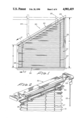
- FIG. 1 is a side elevational view of the described window covering unit shown mounted onto a rack to simulate final mounting.
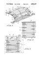
- FIG. 2 is a perspective, partially fragmentary view showing parts of the headrail in exploded relation.
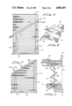
- FIG. 3 is a perspective view of a rectangular window covering unit in a first stage for conversion to an A-frame.
- FIG. 4 is a front elevational view of the window covering unit of FIG. 3 shown fully extended.
- FIG. 5 is a front elevational view of the covering unit of FIG. 4 shown in a special hanging rack for marking the predetermined angle of the upper edge.
- FIG. 6 shows the laying out the cutting angle on the covering unit fabric.
- FIG. 7 shows the fabric of FIG. 6 trimmed to the predetermined angular edge.
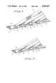
- FIG. 8 shows the formation of end tabs on the angularly cut edge of the fabric.
- FIG. 9 shows the tabs of the fabric stapled onto the inner rail.
- FIG. 10 shows the stapled tabs trimmed to remove excess tabs.
- FIG. 11 is a side elevational, sectional view taken along the lines 11--11 of FIG. 1.
- an A-frame wall covering unit the fabrication of which we are particularly concerned with here is identified generally as 20 and is seen to include in its major parts an extent of pleated fabric 21 hanging from an angularly disposed headrail 22, and an adjustment cord 23 which enables raising and lowering the pleated fabric 21, as desired.
- First and second brackets 24 and 25 (shown in dotted line) form a rack for use in manufacturing and inspection of completed window covering units in simulated final mounting.
- the A-frame window covering unit differs from conventional window covering units employing a pleated fabric essentially in that the upper headrail 22, instead of being disposed in a generally horizontal position with respect to the hanging fabric, is arranged at an angle in order to accommodate an angular internal ceiling surface, or to align with and cover an angular window top, for example. Accordingly, at the right side there is depicted in FIG. 1 pleated fabric 21 extending upwardly a total distance of A which is greater than the distance B as measured along the left side.
- the adjustment cord 23 interconnects through the headrail to first and second cords 27 and 28 threaded through a plurality of aligned openings formed in the pleated fabric along two lines parallel to the right edge and to the left edge of the pleated fabric, respectively. Accordingly, by manipulation of the cord 23 each of the cords 27 and 28 are raised or lowered depending upon the adjustment direction of cord 23.
- a locking means 29, only represented schematically in FIG. 2, is of conventional design and permits the pleated fabric 21 to stay at any particular predetermined location until moved to a further location.
- the pleated fabric in the region between the upper and lower edges of the canted headrail 22 be folded that amount necessary to appear continuous and consistent with the rest of the fabric as it hangs downwardly. This is accomplished as described herein in a manner that will also reliably secure the window covering fabric to the head rail from which it hangs and without exhibiting puckering or distortion of the partially folded fabric located between the two ends of the angularly disposed headrail.
- two inner rails 30 and 31 and a bottom rail 32 are cut to the desired width of the final window covering unit or shade (FIG. 3).
- the opposite ends of the presized extent of fabric 21 is stapled (33) to the two properly dimensioned inner rails 30 and 31.
- the fabric package is punched and grommeted to make it amenable for cording.
- the bottom rail is then assembled in the normal way to the inner rail except that the headrail and cord lock is not provided. The entire assembly to this point is shown in FIG. 4 extended vertically.
- an inspection rack 34 generally includes an elongated rectangular member 35 which is conveniently mounted horizontally and has at spaced intervals first and second U-shaped hangers 36 and 37 onto which an inner rail may be slid in order to support the shade in hanging relation during further processing.
- the shade as shown in FIG. 5 has the rail 32 held by the hangers 36 and 37 allowing the shade to hang downwardly.
- the shade is extended to its maximum use length plus approximately one inch and the cords are clipped to maintain the shade at that overall height.
- the lowest height of the shade is marked on the left in any suitable manner and on the right side the highest point is also marked (i.e., L.H. and H.H.). These two marks correspond to the dimensions B and A, respectively, shown in FIG. 1.
- the shade is removed from the inspection rack and stretched out flat on a smooth, horizontal surface table (not shown) (FIG. 6).
- a straight edge 38 e.g., approximately one inch wide
- the fabric in the area of the angle to be cut between the two marks on the edges is flattened out on the table surface.
- a first line 39 is drawn joining the two marks L.H. and H.H. and a second line 40 using the opposite side of the straight edge is drawn which is parallel to and approximately one inch (i.e., width of straight edge) from the first line.
- the fabric is then cut along the first line 39 providing an upper edge to the fabric arranged at the desired predetermined angle.
- Each of the pleat lines is then cut from the outer angled edge 39 to the second line 40 forming tabs 41.
- Each of the tabs are then folded along the second line 40 in the same direction and are firmly creased (FIGS. 7 and 8).
- the tabs 41 of each set of two adjacent pleats may be bent to overlap each other forming a three-sided box pleat and the overlapping tabs are taped together using a small piece of masking tape.
- the fabric portion of the shade is then placed on the inner rail against limit stop 44 and the tabs 41 are stapled (43) in place so that the fabric will extend along substantially the center line of the rail. More particularly, the stapling is arranged so as to extend along the centerline axis of the inner rail and in that way insure proper location. When all of the fabric has been stapled to the rail, the tabs are trimmed back slightly from the rail ends as shown in FIG. 10.
- the A-frame window covering unit or shade is now complete and can be mounted to a wall as shown in FIG. 1.
- this fabric maintaining an appearance consistent with the remainder of the fabric as a result of the box-pleat formation (FIG. 9) during fabrication of the predetermined angularly cut fabric edge. That is, in securing the tabs 41 to the angularly disposed rail 22, the tabs are so arranged in relation to each other that when the pleated material is all extended and hanging, it will give a consistent and uniform appearance with no puckering or other distortion.
- the invention has been described in connection with having the upper rail 22 angularly disposed with respect to a horizontal lower rail 26, these can be reversed and still be within the spirit of the invention. That is, the upper rail may be horizontal and the lower rail angularly oriented, in which case the pleated material would be cut and secured to the lower rail 26 in the same manner as previously described herein for securing to the upper rail.
Landscapes
- Engineering & Computer Science (AREA)
- Structural Engineering (AREA)
- Architecture (AREA)
- Civil Engineering (AREA)
- Blinds (AREA)
Abstract
Description
Claims (5)
Priority Applications (1)
| Application Number | Priority Date | Filing Date | Title |
|---|---|---|---|
| US07/293,054 US4901419A (en) | 1989-01-03 | 1989-01-03 | A-frame window covering mounting arrangement |
Applications Claiming Priority (1)
| Application Number | Priority Date | Filing Date | Title |
|---|---|---|---|
| US07/293,054 US4901419A (en) | 1989-01-03 | 1989-01-03 | A-frame window covering mounting arrangement |
Publications (1)
| Publication Number | Publication Date |
|---|---|
| US4901419A true US4901419A (en) | 1990-02-20 |
Family
ID=23127455
Family Applications (1)
| Application Number | Title | Priority Date | Filing Date |
|---|---|---|---|
| US07/293,054 Expired - Lifetime US4901419A (en) | 1989-01-03 | 1989-01-03 | A-frame window covering mounting arrangement |
Country Status (1)
| Country | Link |
|---|---|
| US (1) | US4901419A (en) |
Cited By (29)
| Publication number | Priority date | Publication date | Assignee | Title |
|---|---|---|---|---|
| US5044686A (en) * | 1989-06-19 | 1991-09-03 | Acenbrack Donald F | Retractable horizontal conveyance shade apparatus |
| US5092382A (en) * | 1987-12-15 | 1992-03-03 | K. Bratschi, Silent Gliss | Apparatus for raising and lowering a window blind |
| US5176192A (en) * | 1987-03-25 | 1993-01-05 | Verosol Usa Inc. | Shade and bottomrail therefor |
| US5692550A (en) * | 1994-03-10 | 1997-12-02 | Cooper Industries, Inc. | Cellular shade material |
| US5701940A (en) * | 1994-03-10 | 1997-12-30 | Cooper Industries, Inc. | Cellular shade |
| US5860464A (en) * | 1994-03-08 | 1999-01-19 | Schon B.V. | Retractable blind or shade assembly |
| US6003217A (en) * | 1991-07-08 | 1999-12-21 | Newell Operating Company | Size-in-store pleated shade and method and apparatus of sizing |
| US6095222A (en) * | 1999-02-18 | 2000-08-01 | Newell Operating Co. | Lift cord adjustment system |
| US6604443B2 (en) | 2001-07-23 | 2003-08-12 | Newell Window Furnishings, Inc. | Blind and shade cutting center |
| US20040069104A1 (en) * | 2001-07-23 | 2004-04-15 | Caputo Thomas A. | Modular blind cutting center |
| US20040173079A1 (en) * | 2003-03-03 | 2004-09-09 | Caputo Thomas A. | Adjustable blind cutting device |
| US20040173078A1 (en) * | 2003-03-03 | 2004-09-09 | Sean Gilboy | Blind cutting center |
| US20040173066A1 (en) * | 2003-03-03 | 2004-09-09 | Joshua Abdollahzadeh | Blind cutting center with multi-speed saw |
| US20040173076A1 (en) * | 2003-03-03 | 2004-09-09 | Joseph Potts | Automatically configurable blind cutting center |
| US6973364B2 (en) | 2003-03-03 | 2005-12-06 | Schwartz David A | Remotely connected blind cutting center |
| US20060042761A1 (en) * | 2004-08-27 | 2006-03-02 | Danelle Larsen | Lowerable blind for irregularly-shaped windows |
| US20060042760A1 (en) * | 2004-08-27 | 2006-03-02 | Danelle Larsen | Adjustable blind for oddly-shaped windows |
| US7036412B2 (en) | 2003-03-03 | 2006-05-02 | Newell Window Furnishings, Inc. | Blind cutting center with detachable vacuum bag |
| WO2007065249A1 (en) * | 2005-12-05 | 2007-06-14 | Dung Viet Pham | Window blind system |
| US20070239551A1 (en) * | 2006-03-30 | 2007-10-11 | Zeller Michelle G | Method and apparatus for a product ordering system |
| US20090031876A1 (en) * | 2007-07-31 | 2009-02-05 | Newell Window Furnishings, Inc. | Window covering sizing method and apparatus |
| US20110056353A1 (en) * | 2007-07-31 | 2011-03-10 | Newell Window Furnishings, Inc. | Window covering sizing method and apparatus |
| US20110056345A1 (en) * | 2007-07-31 | 2011-03-10 | Newell Window Furnishings, Inc. | Window covering sizing method and apparatus |
| US20110056348A1 (en) * | 2007-07-31 | 2011-03-10 | Newell Window Furnishings, Inc. | Window covering sizing method and apparatus |
| US20110214795A1 (en) * | 2010-03-04 | 2011-09-08 | Despins Maurice L | Seaming Tape and Method for Using Same |
| US8256333B2 (en) | 2007-07-31 | 2012-09-04 | Newell Window Furnishings, Inc. | Window covering sizing method and apparatus |
| US8479925B2 (en) | 2010-07-19 | 2013-07-09 | Newell Window Furnishings, Inc. | Display system |
| US9266639B2 (en) | 2010-07-19 | 2016-02-23 | Newell Window Furnishings, Inc. | Blind packaging and methods of cutting window coverings |
| US9982481B2 (en) * | 2015-11-25 | 2018-05-29 | Mario M Marocco | Arch window covering with control |
Citations (1)
| Publication number | Priority date | Publication date | Assignee | Title |
|---|---|---|---|---|
| US4518025A (en) * | 1983-11-10 | 1985-05-21 | Verosol Usa Inc. | Sun blind construction |
-
1989
- 1989-01-03 US US07/293,054 patent/US4901419A/en not_active Expired - Lifetime
Patent Citations (1)
| Publication number | Priority date | Publication date | Assignee | Title |
|---|---|---|---|---|
| US4518025A (en) * | 1983-11-10 | 1985-05-21 | Verosol Usa Inc. | Sun blind construction |
Cited By (61)
| Publication number | Priority date | Publication date | Assignee | Title |
|---|---|---|---|---|
| US5176192A (en) * | 1987-03-25 | 1993-01-05 | Verosol Usa Inc. | Shade and bottomrail therefor |
| US5092382A (en) * | 1987-12-15 | 1992-03-03 | K. Bratschi, Silent Gliss | Apparatus for raising and lowering a window blind |
| US5044686A (en) * | 1989-06-19 | 1991-09-03 | Acenbrack Donald F | Retractable horizontal conveyance shade apparatus |
| US6003217A (en) * | 1991-07-08 | 1999-12-21 | Newell Operating Company | Size-in-store pleated shade and method and apparatus of sizing |
| US5860464A (en) * | 1994-03-08 | 1999-01-19 | Schon B.V. | Retractable blind or shade assembly |
| US5692550A (en) * | 1994-03-10 | 1997-12-02 | Cooper Industries, Inc. | Cellular shade material |
| US5701940A (en) * | 1994-03-10 | 1997-12-30 | Cooper Industries, Inc. | Cellular shade |
| US6095222A (en) * | 1999-02-18 | 2000-08-01 | Newell Operating Co. | Lift cord adjustment system |
| US7100485B2 (en) | 2001-07-23 | 2006-09-05 | Newell Window Furnishings, Inc. | Blind and shade cutting center |
| US20030209118A1 (en) * | 2001-07-23 | 2003-11-13 | Roberts David C. | Method of positioning a window covering ina sizing mechanism |
| US20040069104A1 (en) * | 2001-07-23 | 2004-04-15 | Caputo Thomas A. | Modular blind cutting center |
| US7681480B2 (en) | 2001-07-23 | 2010-03-23 | Newell Window Furnishings, Inc. | Blind and shade cutting center for cutting two different window covering products |
| US6604443B2 (en) | 2001-07-23 | 2003-08-12 | Newell Window Furnishings, Inc. | Blind and shade cutting center |
| US8161857B2 (en) | 2001-07-23 | 2012-04-24 | Newell Window Furnishings, Inc. | Blind and shade cutting center for cutting two different window covering products |
| US8286538B2 (en) | 2001-07-23 | 2012-10-16 | Newell Window Furnishings, Inc. | Blind and shade cutting center for cutting two different window covering products |
| US7069833B2 (en) | 2001-07-23 | 2006-07-04 | Newell Window Furnishings, Inc. | Moveable blind and shade cutting center |
| US7104175B2 (en) | 2001-07-23 | 2006-09-12 | Newell Window Furnishings, Inc. | Blind and shade cutting center with center locating system |
| US8499670B2 (en) | 2001-07-23 | 2013-08-06 | Newell Window Furnishings, Inc. | Modular blind cutting center |
| US7007576B2 (en) | 2001-07-23 | 2006-03-07 | Newell Window Furnishings, Inc. | Method of positioning a window covering in a sizing mechanism |
| US20100107839A1 (en) * | 2001-07-23 | 2010-05-06 | Newell Window Furnishings, Inc. | Blind and shade cutting center for cutting two different window covering products |
| US7040205B2 (en) | 2001-07-23 | 2006-05-09 | Newell Window Furnishings, Inc | Blind and shade cutting center with movable cutting station |
| US7069832B2 (en) | 2001-07-23 | 2006-07-04 | Newell Window Furnishings, Inc. | Blind and shade cutting center with movable locator |
| US6973364B2 (en) | 2003-03-03 | 2005-12-06 | Schwartz David A | Remotely connected blind cutting center |
| US7059230B2 (en) | 2003-03-03 | 2006-06-13 | Caputo Thomas A | Adjustable blind cutting device |
| US7036412B2 (en) | 2003-03-03 | 2006-05-02 | Newell Window Furnishings, Inc. | Blind cutting center with detachable vacuum bag |
| US10792739B2 (en) | 2003-03-03 | 2020-10-06 | Hunter Douglas Industries Switzerland Gmbh | Automatically configurable blind cutting center |
| US7178439B2 (en) | 2003-03-03 | 2007-02-20 | Newell Window Furnishings, Inc. | Blind cutting center |
| US20040173076A1 (en) * | 2003-03-03 | 2004-09-09 | Joseph Potts | Automatically configurable blind cutting center |
| US20040173066A1 (en) * | 2003-03-03 | 2004-09-09 | Joshua Abdollahzadeh | Blind cutting center with multi-speed saw |
| US20110088524A1 (en) * | 2003-03-03 | 2011-04-21 | Newell Window Furnishings, Inc. | Automatically Configurable Blind Cutting Center |
| US20040173078A1 (en) * | 2003-03-03 | 2004-09-09 | Sean Gilboy | Blind cutting center |
| US7810418B2 (en) | 2003-03-03 | 2010-10-12 | Newell Window Furnishings, Inc. | Automatically configurable blind cutting center |
| US20040173079A1 (en) * | 2003-03-03 | 2004-09-09 | Caputo Thomas A. | Adjustable blind cutting device |
| US7383870B2 (en) * | 2004-08-27 | 2008-06-10 | Danelle Larsen | Adjustable blind for oddly-shaped windows |
| US20060042761A1 (en) * | 2004-08-27 | 2006-03-02 | Danelle Larsen | Lowerable blind for irregularly-shaped windows |
| US20060042760A1 (en) * | 2004-08-27 | 2006-03-02 | Danelle Larsen | Adjustable blind for oddly-shaped windows |
| US7302985B2 (en) * | 2004-08-27 | 2007-12-04 | Danelle Larsen | Lowerable blind for irregularly-shaped windows |
| AU2006322589B2 (en) * | 2005-12-05 | 2012-03-22 | Dung Viet Pham | Window blind system |
| WO2007065249A1 (en) * | 2005-12-05 | 2007-06-14 | Dung Viet Pham | Window blind system |
| US20070239551A1 (en) * | 2006-03-30 | 2007-10-11 | Zeller Michelle G | Method and apparatus for a product ordering system |
| US8322260B2 (en) | 2007-07-31 | 2012-12-04 | Newell Window Furnishings, Inc. | Window covering sizing method and apparatus |
| US11872716B2 (en) | 2007-07-31 | 2024-01-16 | Hunter Douglas Industries Switzerland Gmbh | Window covering sizing method and apparatus |
| US7987754B2 (en) | 2007-07-31 | 2011-08-02 | Newell Window Furnishings, Inc. | Window covering sizing method and apparatus |
| US20110056348A1 (en) * | 2007-07-31 | 2011-03-10 | Newell Window Furnishings, Inc. | Window covering sizing method and apparatus |
| US8256333B2 (en) | 2007-07-31 | 2012-09-04 | Newell Window Furnishings, Inc. | Window covering sizing method and apparatus |
| US20110056345A1 (en) * | 2007-07-31 | 2011-03-10 | Newell Window Furnishings, Inc. | Window covering sizing method and apparatus |
| US20100206144A1 (en) * | 2007-07-31 | 2010-08-19 | Newell Window Furnishings Inc. | Window covering sizing method and apparatus |
| US10786921B2 (en) | 2007-07-31 | 2020-09-29 | Hunter Douglas Industries Switzerland Gmbh | Window covering sizing method and apparatus |
| US20110056353A1 (en) * | 2007-07-31 | 2011-03-10 | Newell Window Furnishings, Inc. | Window covering sizing method and apparatus |
| US8631732B1 (en) | 2007-07-31 | 2014-01-21 | Newell Window Furnishings, Inc. | Window covering sizing method and apparatus |
| US8839701B2 (en) | 2007-07-31 | 2014-09-23 | Newell Window Furnishings, Inc. | Window covering sizing method and apparatus |
| US20090031876A1 (en) * | 2007-07-31 | 2009-02-05 | Newell Window Furnishings, Inc. | Window covering sizing method and apparatus |
| US9427813B2 (en) | 2007-07-31 | 2016-08-30 | Newell Window Furnishing, Inc. | Window covering sizing method and apparatus |
| US9440368B2 (en) | 2007-07-31 | 2016-09-13 | Newell Window Furnishings, Inc. | Window covering sizing method and apparatus |
| US9581181B2 (en) | 2010-03-04 | 2017-02-28 | Omnimart Distributions Inc. | Seaming tape and method for using same |
| US20110214795A1 (en) * | 2010-03-04 | 2011-09-08 | Despins Maurice L | Seaming Tape and Method for Using Same |
| US9266639B2 (en) | 2010-07-19 | 2016-02-23 | Newell Window Furnishings, Inc. | Blind packaging and methods of cutting window coverings |
| US10450129B2 (en) | 2010-07-19 | 2019-10-22 | Levolor, Inc. | Blind packaging and methods of cutting window coverings |
| US11312566B2 (en) | 2010-07-19 | 2022-04-26 | Hunter Douglas Industries Switzerland Gmbh | Blind packaging and methods of cutting window coverings |
| US8479925B2 (en) | 2010-07-19 | 2013-07-09 | Newell Window Furnishings, Inc. | Display system |
| US9982481B2 (en) * | 2015-11-25 | 2018-05-29 | Mario M Marocco | Arch window covering with control |
Similar Documents
| Publication | Publication Date | Title |
|---|---|---|
| US4901419A (en) | A-frame window covering mounting arrangement | |
| US4069857A (en) | Roman shade and method for making same | |
| US7124802B2 (en) | Cascade shade | |
| US5341864A (en) | Adjustable expandable and collapsible shade | |
| EP1697611B1 (en) | Retractable shade for coverings for architectural openings | |
| US4544011A (en) | Pleat screen | |
| US5701940A (en) | Cellular shade | |
| US4733710A (en) | Vehicular shade | |
| US5692550A (en) | Cellular shade material | |
| US20080083508A1 (en) | Shade construction | |
| EP0451912B1 (en) | Retractable roman shade, profile for said shade and a method for pleating a web of material by means of said profile to form said shade | |
| US5121783A (en) | Window covering apparatus | |
| US4765388A (en) | Roman blind | |
| US4422492A (en) | Insulating shade device | |
| CN101672156A (en) | Temporary window covering | |
| AU697350B2 (en) | Pleated blinds | |
| US20060096716A1 (en) | Customizable row assembly and method of manufacturing a window covering | |
| US4317481A (en) | Thermal barrier | |
| EP1679422A1 (en) | Mounting system for end vanes in vertical vane blind | |
| US6510806B1 (en) | Covering for blinds | |
| US7240714B2 (en) | System for suspending a free-hanging covering for an architectural opening | |
| JPH052790Y2 (en) | ||
| AU2016201091B2 (en) | Retractable shade for coverings for architectural openings | |
| EP1581717B1 (en) | Fabric covered rail for pleated shade | |
| CA2181112C (en) | Cellular shade |
Legal Events
| Date | Code | Title | Description |
|---|---|---|---|
| AS | Assignment |
Owner name: HOUSEHOLD COMMERCIAL OF CALIFORNIA, INC., ILLINOIS Free format text: SECURITY INTEREST;ASSIGNOR:HOME FASHIONS, INC.;REEL/FRAME:005077/0200 Effective date: 19881216 |
|
| AS | Assignment |
Owner name: HOME FASHIONS, INC., 7150 FENWICK LANE, WESTMINSTE Free format text: ASSIGNMENT OF ASSIGNORS INTEREST.;ASSIGNOR:VOSS, ROBERT J.;REEL/FRAME:005111/0604 Effective date: 19890811 |
|
| STCF | Information on status: patent grant |
Free format text: PATENTED CASE |
|
| AS | Assignment |
Owner name: HELLER FINANCIAL, INC. Free format text: SECURITY INTEREST;ASSIGNOR:HOME FASHIONS, INC.;REEL/FRAME:005818/0816 Effective date: 19901005 |
|
| FEPP | Fee payment procedure |
Free format text: PAYOR NUMBER ASSIGNED (ORIGINAL EVENT CODE: ASPN); ENTITY STATUS OF PATENT OWNER: LARGE ENTITY |
|
| FPAY | Fee payment |
Year of fee payment: 4 |
|
| AS | Assignment |
Owner name: NEWELL OPERATING COMPANY, ILLINOIS Free format text: ASSIGNMENT OF ASSIGNORS INTEREST;ASSIGNOR:HOME FASHIONS, INC.;REEL/FRAME:007286/0076 Effective date: 19940829 |
|
| FEPP | Fee payment procedure |
Free format text: PAYER NUMBER DE-ASSIGNED (ORIGINAL EVENT CODE: RMPN); ENTITY STATUS OF PATENT OWNER: LARGE ENTITY |
|
| FPAY | Fee payment |
Year of fee payment: 8 |
|
| FPAY | Fee payment |
Year of fee payment: 12 |
|
| AS | Assignment |
Owner name: MEGTEC SYSTEMS, S.A.S., WISCONSIN Free format text: RELEASED BY SECURED PARTY;ASSIGNOR:LEHMAN COMMERCIAL PAPER, INC.;REEL/FRAME:021630/0602 Effective date: 20080924 Owner name: MEGTEC SYSTEMS, INC., WISCONSIN Free format text: RELEASED BY SECURED PARTY;ASSIGNOR:LEHMAN COMMERCIAL PAPER, INC.;REEL/FRAME:021630/0602 Effective date: 20080924 Owner name: MEGTEC SYSTEMS AMAL AB, WISCONSIN Free format text: RELEASED BY SECURED PARTY;ASSIGNOR:LEHMAN COMMERCIAL PAPER, INC.;REEL/FRAME:021630/0602 Effective date: 20080924 Owner name: MEGTEC SYSTEMS AUSTRALIA, INC., WISCONSIN Free format text: RELEASED BY SECURED PARTY;ASSIGNOR:LEHMAN COMMERCIAL PAPER, INC.;REEL/FRAME:021630/0602 Effective date: 20080924 Owner name: MTS ASIA, INC., WISCONSIN Free format text: RELEASED BY SECURED PARTY;ASSIGNOR:LEHMAN COMMERCIAL PAPER, INC.;REEL/FRAME:021630/0602 Effective date: 20080924 Owner name: MEGTEC SYSTEMS AB, WISCONSIN Free format text: RELEASED BY SECURED PARTY;ASSIGNOR:LEHMAN COMMERCIAL PAPER, INC.;REEL/FRAME:021630/0602 Effective date: 20080924 Owner name: MEGTEC SYSTEMS KG, WISCONSIN Free format text: RELEASED BY SECURED PARTY;ASSIGNOR:LEHMAN COMMERCIAL PAPER, INC.;REEL/FRAME:021630/0602 Effective date: 20080924 Owner name: SEQUA GMBH & CO., WISCONSIN Free format text: RELEASED BY SECURED PARTY;ASSIGNOR:LEHMAN COMMERCIAL PAPER, INC.;REEL/FRAME:021630/0602 Effective date: 20080924 |