US4900187A - Hydraulic actuator and lift apparatus - Google Patents
Hydraulic actuator and lift apparatus Download PDFInfo
- Publication number
- US4900187A US4900187A US07/113,089 US11308987A US4900187A US 4900187 A US4900187 A US 4900187A US 11308987 A US11308987 A US 11308987A US 4900187 A US4900187 A US 4900187A
- Authority
- US
- United States
- Prior art keywords
- cylinder
- lifting platform
- dock
- piston assembly
- transmitting component
- Prior art date
- Legal status (The legal status is an assumption and is not a legal conclusion. Google has not performed a legal analysis and makes no representation as to the accuracy of the status listed.)
- Expired - Fee Related
Links
Images

Classifications
-
- B—PERFORMING OPERATIONS; TRANSPORTING
- B63—SHIPS OR OTHER WATERBORNE VESSELS; RELATED EQUIPMENT
- B63C—LAUNCHING, HAULING-OUT, OR DRY-DOCKING OF VESSELS; LIFE-SAVING IN WATER; EQUIPMENT FOR DWELLING OR WORKING UNDER WATER; MEANS FOR SALVAGING OR SEARCHING FOR UNDERWATER OBJECTS
- B63C3/00—Launching or hauling-out by landborne slipways; Slipways
- B63C3/06—Launching or hauling-out by landborne slipways; Slipways by vertical movement of vessel, i.e. by crane
Definitions
- the present invention relates to fluid pressure mechanism for applying a pulling force and to lift apparatus powered by such mechanism.
- an operating cylinder has an internal piston moved lengthwise of the cylinder by introduction of fluid under pressure.
- a rigid plunger has an inner end connected to the piston and an outer free end portion extending axially through an end of the cylinder.
- Such a jack requires a large space for the range of motion to be achieved.
- the space in which the jack is mounted must accommodate the entire length of the cylinder plus the desired range of motion of the plunger which, at most, would be approximately equal to the length of the cylinder. Consequently, the most compact installation must provide space for at least twice the desired length of linear motion of the plunger if the simple known fluid pressure jack is used.
- hydraulically powered lifts some of which have been adapted for underwater installation to raise and lower a large boat or a seaplane, for example.
- hydraulically powered lifts some of which have been adapted for underwater installation to raise and lower a large boat or a seaplane, for example.
- inexpensive compact lift specially adapted to be mounted on or adjacent to a dock for conveniently raising and lowering a small watercraft such as a skiff, rowboat, canoe or jet ski.
- the present invention provides an improved fluid pressure actuator of the type using an elongated operating cylinder and an internal piston.
- a flexible force-transmitting component is connected to the piston and extends axially through a leakproof but sliding fitting at one end of the cylinder.
- such flexible component is a cable sheathed in smooth slippery plastic.
- Such cable replaces the rigid plunger of a conventional fluid pressure cylinder actuator and is effective for applying pulling but not pushing force by introduction of fluid under pressure into the cylinder at the side of the piston to which the cable is connected.
- the piston preferably has two axially spaced disks, ne of which is designed to prevent fluid under pressure from leaking past the piston, and the other of which is provided primarily to guide the composite piston assembly for axial movement without racking or canting relative to the cylinder.
- the actuator in accordance with the present invention provides the force for raising a lift platform which is guided for vertical movement along upright stationary rails.
- the rails are part of a stationary frame connected to a dock and the lift platform is adapted for raising and lowering a small watercraft.
- the actuator with its flexible force-transmitting component allows a particularly compact overall construction. By using water as the fluid introduced under pressure into the actuator, a very simple and inexpensive operation is assured without possibility of undesirable contamination by leaks and without requiring special apparatus for pumping or storing other operating liquids or gases.
- FIG. 1 is a somewhat diagrammatic side elevation of a hydraulic actuator in accordance with the present invention with parts broken away such that the internal components of such actuator are seen primarily in axial section; and FIG. 2 is a fragmentary, enlarged, axial section of an end portion of such actuator.
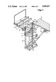
- FIG. 3 is a top perspective of hydraulic lift apparatus in accordance with the present invention utilizing the actuator of FIGS. 1 and 2, with parts broken away; and
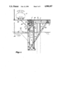
- FIG. 4 is a somewhat diagrammatic side elevation of such lift apparatus, with some parts broken away, illustrating the lift apparatus as mounted on a conventional dock.
- FIG. 5 (on the drawing sheet with FIGS. 1 and 2) is a somewhat diagrammatic side elevation of a modified hydraulic actuator in accordance with the present invention.
- the preferred hydraulic actuator 1 in accordance with the present invention has an elongated cylinder 2 with a bottom end cap 3 and a top end cap 4 substantially closing the cylinder interior pressure cavity 5.
- a piston assembly 6 including axially spaced diametral disks 7 and 8 connected by an elongated central stud 9.
- Disks 7 and 8 fit closely in the cylinder cavity but not so closely as to interfere appreciably with longitudinal sliding movement of the piston assembly.
- Disk 7, the top disk as viewed in FIG. 1, carries a flexible gasket or cup 10 including an upturned lip portion 11 to prevent operating liquid from leaking past the piston assembly.
- Operating liquid introduced into the upper portion of the cylinder cavity tends to press the cup lip 11 outward against the smooth inner wall of the cylinder 2.
- the bottom disk, disk 8, is spaced a substantial distance below the top disk by the stud 9, preferably at least several times the axial extent of either disk, to guide longitudinal movement of the assembly while preventing racking or canting relative to the cylinder.
- An integral portion of the piston assembly 6 is an eye bolt 12 having a shank 13 screwed into the central stud 9 and clamping the flexible piston cup 10 against the top piston disk 8 by engagement against a central washer 14.
- the diameter of washer 14 is only slightly less than the diameter of disk 7 so that substantially the entire central portion of the flexible cup 10 is rigidified by being clamped between the rigid washer and disk.
- the eye of bolt 12 serves as the connection point for one end portion 15 of an elongated, flexible, force-transmitting component 16 extending lengthwise axially of the cylinder 2 away from the piston assembly 6.
- the flexible component 16 includes a core cable 17 and an outer smooth plastic sheath 18.
- FIG. 2 also illustrates in greater detail the top fitting 19 through which the sheathed cable 16 extends.
- Such fitting 19 includes a plastic nipple 20 screwed tightly into the horizontal portion of the cylinder cap 4 and an upper externally threaded neck 21.
- the bore 22 of the nipple 20 is tapered downward and receives a correspondingly tapered resilient plug member 23 having a central bore for the sheathed cable 16.
- a screw cap 24 has a central bore registered with the bore of plug member 23. When screwed onto the nipple neck portion 21, cap 24 forces the plug member progressively downward in the tapered bore 22 such that a substantially leakproof but sliding fit of the sheathed cable 16 in the plug member 23 is assured.
- the fitting 19 is of the type known to have been used in some marine applications such as where steering or control cables extend through a panel or bulkhead of a boat.
- fluid under pressure preferably water
- inlet conduit 25 to force the piston assembly 6 downward, thereby applying pulling force and imparting axial motion to the flexible force-transmitting component 16.
- the range of travel of the piston assembly and, hence, the force-transmitting component 16 is limited only by the length of the cylinder.
- An outlet or vent opening 26 is provided adjacent to the bottom of the cylinder 2 so that movement of the piston assembly is not resisted.
- a reservoir or accumulator can be connected to the vent opening 26 if desired but is not required in the preferred application described below.
- the actuator 1 is mounted in upright position on a stationary frame which includes upright legs or rails 30 of U cross section, such rails 30 being spaced apart and having their grooves or ways facing each other.
- the top ends of the rails 30 are joined by an angle cross member having a horizontal flange 31 connected along a top margin of a conventional dock D.
- such dock can have a supporting vertical piling P carrying cross support beams B and joists including an edge joist J and central joist J' for the top deck or flooring F.
- all frame components are flush with or below the top surface of the dock.
- the bottom end portions of the rails 30 are supported by upward and inward extending braces 36 which can have their top end portions secured to the central joist J' and flooring F of the dock.
- bottom end portions of rails 30 also are joined by a bottom cross member 32 forming one side of a rectangular bottom frame which has a central horizontal member 33 to which the bottom end portion of the actuator 1 is connected.
- the actuator cylinder 2 is supported intermediate its ends by a collar 34 carried by angular support bars 35 extending inward from the spaced rails 30.
- the stationary components of the lift apparatus are completed by a top stationary frame 37 mounted on the upright rails 30 and carrying a central pulley 38 underneath the dock flooring F for rotation about a horizontal transverse axis.
- the inner edge portion of the pulley is aligned axially with the actuator cylinder 2 for receiving the elongated, flexible, force-transmitting component (sheathed cable) 16 which extends up and over the pulley and then downward to its outer end portion 39.
- Such outer end portion 39 of the cable 16 is connected to the bottom horizontal cross member 40 of a lift carriage which has opposite upright side plates 41 carrying rollers 42 for movement in the grooves or ways of the U cross section rails 30.
- Such plates 41 carry triangular gusset-like supports 43 for the lift frame or platform 44 which can have elongated pads 45 for the small watercraft to be lifted. As seen in FIG. 4, such craft can be a jet ski S, for example.
- the vertically moving carriage and its lift platform 44 initially are in the broken line position with the support pads 45 at about the water level.
- the internal piston assembly 6 of the actuator 1 will be close to the top of the cylinder 2.
- Introduction of fluid, preferably water, through the inlet conduit 25 applies force to the piston assembly 6 moving it downward to the position shown in FIG. 4 which raises the carriage and its lifting platform 44 to the solid line position.
- the maximum range of movement of the lifting platform is about equal to or slightly less than the overall length of the actuator cylinder 2, but the cylinder can be mounted upright much closer to the guide pulley 38 to impart the vertical motion to the lift platform and carriage.
- a known fluid pressure jack with a rigid plunger were used, the compact mounting would not be possible or complicated movement-exaggerating mechanical components would have to be used.
- the lifting platform and carriage are locked automatically in the raised position such as by the latch hook 50 pivoted on one of the carriage sideplates 41 and automatically hooked over a pin 51 mounted on a bracket 52 extending from the adjacent dock edge. Consequently, the carriage is retained in the raised position even if fluid pressure in the top cylinder cavity 5 is relieved.
- the top supporting surface of the lifting platform is at least as high as the top surface of the dock. Since the side of the lifting platform adjacent to the dock is open and unobstructed, the watercraft can be conveniently loaded onto or off the platform.
- the platform When it is desired to lower the lift platform, the platform must be raised by operation of the actuator 1 before the latch hook 50 can be moved manually away from its pin, whereupon the lift platform and carriage is lowered by gravity as water is forced outward through the small conduit 25.
- the frame and lift carriage components can be constructed of corrosion-resistant metals, whereas the actuator can be constructed of readily available plastic materials such as PVC plastic.
- the actuator and lift are engineered so that standard water pressure such as from a garden hose is sufficient to raise and lower the lift carriage and the desired watercraft with no supplemental fluid pressure pumps being required.
- standard water pressure such as from a garden hose is sufficient to raise and lower the lift carriage and the desired watercraft with no supplemental fluid pressure pumps being required.
- the use of water in the underwater installation eliminates any necessity for a completely fluid-tight closed piping system with accumulators and reservoirs, for example. Small leaks may slightly lessen the lifting effectiveness, but have no contamination effect nor do they require immediate maintenance to maintain operability of the system.
- the platform 44 is lowered by gravity.
- the modified actuator 1' shown in FIG. 5 can be used.
- Such actuator has the operating cylinder 2 and internal piston assembly 6 substantially indentical to the cylinder and piston assembly of the previously described embodiment, but with opposite stretches 16' and 16" of cable extending axially from the piston assembly and through the opposite ends of the cylinder. Fluid under pressure can be introduced through conduit 25' in one end or conduit 25" in the other end to move the piston assembly and cable in the desired direction. Pulleys can route the cable stretches 16' and 16" to the member or members to be moved.
Landscapes
- Engineering & Computer Science (AREA)
- Mechanical Engineering (AREA)
- Ocean & Marine Engineering (AREA)
- Actuator (AREA)
Abstract
Description
Claims (4)
Priority Applications (1)
| Application Number | Priority Date | Filing Date | Title |
|---|---|---|---|
| US07/113,089 US4900187A (en) | 1987-10-23 | 1987-10-23 | Hydraulic actuator and lift apparatus |
Applications Claiming Priority (1)
| Application Number | Priority Date | Filing Date | Title |
|---|---|---|---|
| US07/113,089 US4900187A (en) | 1987-10-23 | 1987-10-23 | Hydraulic actuator and lift apparatus |
Publications (1)
| Publication Number | Publication Date |
|---|---|
| US4900187A true US4900187A (en) | 1990-02-13 |
Family
ID=22347527
Family Applications (1)
| Application Number | Title | Priority Date | Filing Date |
|---|---|---|---|
| US07/113,089 Expired - Fee Related US4900187A (en) | 1987-10-23 | 1987-10-23 | Hydraulic actuator and lift apparatus |
Country Status (1)
| Country | Link |
|---|---|
| US (1) | US4900187A (en) |
Cited By (18)
| Publication number | Priority date | Publication date | Assignee | Title |
|---|---|---|---|---|
| US5016551A (en) * | 1990-05-15 | 1991-05-21 | National Hydrohoist Company | Lift for water vehicles |
| DE9103949U1 (en) * | 1991-04-02 | 1991-07-25 | Storms, Ernst, 5140 Erkelenz, De | |
| US5090841A (en) * | 1990-09-06 | 1992-02-25 | Brammall, Inc. | Boat lift |
| US5140923A (en) * | 1991-03-25 | 1992-08-25 | Wood Kevin L | Raising and lowering device |
| US5427471A (en) * | 1994-02-03 | 1995-06-27 | Godbersen; Byron I. | Dock mounted boat hoist |
| US5692857A (en) * | 1995-09-21 | 1997-12-02 | Ness; Stewart D. | Lifting floors |
| US5839851A (en) * | 1997-04-22 | 1998-11-24 | Norfolk Fabrication, Inc. | Personal watercraft lift |
| US6591770B1 (en) * | 2000-10-23 | 2003-07-15 | St. Croix Marine Products, Inc. | Boating lift |
| US6598549B1 (en) | 2002-03-20 | 2003-07-29 | Ronald C. Voegeli | Boat lift |
| US6612775B1 (en) | 2002-06-06 | 2003-09-02 | Larry Hewitt | Hydraulic watercraft lift |
| US6845845B2 (en) | 2002-03-13 | 2005-01-25 | Jsv Group Inc. | Water recreation dock |
| US20050179280A1 (en) * | 2004-02-12 | 2005-08-18 | Stabilus Gmbh | Device for opening and closing a vehicle body part |
| US20060177277A1 (en) * | 2005-02-09 | 2006-08-10 | Thomas Samuel M Jr | Extendible building post |
| US20080105186A1 (en) * | 2005-05-10 | 2008-05-08 | Sealift, Inc. | Boat Lifting Apparatus and Method |
| US20100032209A1 (en) * | 2008-08-06 | 2010-02-11 | Atlas Copco Secoroc Llc | Percussion assisted rotary earth bit and method of operating the same |
| US7707955B1 (en) | 2007-08-07 | 2010-05-04 | Sealift, Inc. | Transom platform lifting apparatus and method |
| US20110030970A1 (en) * | 2009-08-07 | 2011-02-10 | Tweedie Steven B | Break-out assembly for a drilling machine |
| US11732431B2 (en) | 2021-06-26 | 2023-08-22 | Jsv Group, Inc. | Submergible water activity platform system |
Citations (13)
| Publication number | Priority date | Publication date | Assignee | Title |
|---|---|---|---|---|
| US728117A (en) * | 1902-04-12 | 1903-05-12 | Bernhard Kirsch | Ship-railway carriage. |
| US1106930A (en) * | 1912-11-11 | 1914-08-11 | William S Potwin | Flexible piston-rod and cylinder therefor. |
| US1503369A (en) * | 1921-04-21 | 1924-07-29 | Lavoie Joseph Pierre | Piston |
| US2598271A (en) * | 1947-01-08 | 1952-05-27 | Francis E Klosterman | Servomotor with lubricated rotatable piston rod |
| US2613915A (en) * | 1949-12-28 | 1952-10-14 | Standard Oil Dev Co | Hoisting device |
| US3033626A (en) * | 1959-07-03 | 1962-05-08 | American Cyanamid Co | Twin-piston element |
| US3062601A (en) * | 1961-01-16 | 1962-11-06 | Hypro Engineering Inc | Piston cup |
| US3319537A (en) * | 1965-11-08 | 1967-05-16 | Flair Line | Piston for pneumatic cylinders |
| US4121840A (en) * | 1977-01-10 | 1978-10-24 | Tol-O-Matic Inc. | Seal assembly |
| US4432664A (en) * | 1981-03-03 | 1984-02-21 | Duraline Products Corporation | Boat hoist |
| SU1118581A1 (en) * | 1982-08-30 | 1984-10-15 | Drozdin Viktor A | "econom" slipway lift |
| US4641996A (en) * | 1984-09-20 | 1987-02-10 | Morton Seal | Side loading boat lifts |
| US4678366A (en) * | 1985-07-31 | 1987-07-07 | Williamson James W | Boat lift |
-
1987
- 1987-10-23 US US07/113,089 patent/US4900187A/en not_active Expired - Fee Related
Patent Citations (13)
| Publication number | Priority date | Publication date | Assignee | Title |
|---|---|---|---|---|
| US728117A (en) * | 1902-04-12 | 1903-05-12 | Bernhard Kirsch | Ship-railway carriage. |
| US1106930A (en) * | 1912-11-11 | 1914-08-11 | William S Potwin | Flexible piston-rod and cylinder therefor. |
| US1503369A (en) * | 1921-04-21 | 1924-07-29 | Lavoie Joseph Pierre | Piston |
| US2598271A (en) * | 1947-01-08 | 1952-05-27 | Francis E Klosterman | Servomotor with lubricated rotatable piston rod |
| US2613915A (en) * | 1949-12-28 | 1952-10-14 | Standard Oil Dev Co | Hoisting device |
| US3033626A (en) * | 1959-07-03 | 1962-05-08 | American Cyanamid Co | Twin-piston element |
| US3062601A (en) * | 1961-01-16 | 1962-11-06 | Hypro Engineering Inc | Piston cup |
| US3319537A (en) * | 1965-11-08 | 1967-05-16 | Flair Line | Piston for pneumatic cylinders |
| US4121840A (en) * | 1977-01-10 | 1978-10-24 | Tol-O-Matic Inc. | Seal assembly |
| US4432664A (en) * | 1981-03-03 | 1984-02-21 | Duraline Products Corporation | Boat hoist |
| SU1118581A1 (en) * | 1982-08-30 | 1984-10-15 | Drozdin Viktor A | "econom" slipway lift |
| US4641996A (en) * | 1984-09-20 | 1987-02-10 | Morton Seal | Side loading boat lifts |
| US4678366A (en) * | 1985-07-31 | 1987-07-07 | Williamson James W | Boat lift |
Cited By (24)
| Publication number | Priority date | Publication date | Assignee | Title |
|---|---|---|---|---|
| US5016551A (en) * | 1990-05-15 | 1991-05-21 | National Hydrohoist Company | Lift for water vehicles |
| USRE34793E (en) * | 1990-05-15 | 1994-11-22 | Hydrohoist International, Inc. | Lift for water vehicles |
| US5090841A (en) * | 1990-09-06 | 1992-02-25 | Brammall, Inc. | Boat lift |
| US5140923A (en) * | 1991-03-25 | 1992-08-25 | Wood Kevin L | Raising and lowering device |
| DE9103949U1 (en) * | 1991-04-02 | 1991-07-25 | Storms, Ernst, 5140 Erkelenz, De | |
| US5427471A (en) * | 1994-02-03 | 1995-06-27 | Godbersen; Byron I. | Dock mounted boat hoist |
| US5692857A (en) * | 1995-09-21 | 1997-12-02 | Ness; Stewart D. | Lifting floors |
| US5839851A (en) * | 1997-04-22 | 1998-11-24 | Norfolk Fabrication, Inc. | Personal watercraft lift |
| US6591770B1 (en) * | 2000-10-23 | 2003-07-15 | St. Croix Marine Products, Inc. | Boating lift |
| US6845845B2 (en) | 2002-03-13 | 2005-01-25 | Jsv Group Inc. | Water recreation dock |
| US6598549B1 (en) | 2002-03-20 | 2003-07-29 | Ronald C. Voegeli | Boat lift |
| US6612775B1 (en) | 2002-06-06 | 2003-09-02 | Larry Hewitt | Hydraulic watercraft lift |
| US20050179280A1 (en) * | 2004-02-12 | 2005-08-18 | Stabilus Gmbh | Device for opening and closing a vehicle body part |
| US7506556B2 (en) * | 2004-02-12 | 2009-03-24 | Stabilus Gmbh | Device for opening and closing a vehicle body part |
| US20060177277A1 (en) * | 2005-02-09 | 2006-08-10 | Thomas Samuel M Jr | Extendible building post |
| US7614829B2 (en) | 2005-02-09 | 2009-11-10 | Thomas Jr Samuel M | Extendible building post |
| US20080105186A1 (en) * | 2005-05-10 | 2008-05-08 | Sealift, Inc. | Boat Lifting Apparatus and Method |
| US7707955B1 (en) | 2007-08-07 | 2010-05-04 | Sealift, Inc. | Transom platform lifting apparatus and method |
| US20100032209A1 (en) * | 2008-08-06 | 2010-02-11 | Atlas Copco Secoroc Llc | Percussion assisted rotary earth bit and method of operating the same |
| US8353369B2 (en) | 2008-08-06 | 2013-01-15 | Atlas Copco Secoroc, LLC | Percussion assisted rotary earth bit and method of operating the same |
| US20110030970A1 (en) * | 2009-08-07 | 2011-02-10 | Tweedie Steven B | Break-out assembly for a drilling machine |
| WO2011016818A1 (en) | 2009-08-07 | 2011-02-10 | Atlas Copco Drilling Solutions Llc | Break-out assembly for a drilling machine |
| US8413728B2 (en) | 2009-08-07 | 2013-04-09 | Atlas Copco Drilling Solutions Llc | Break-out assembly for a drilling machine |
| US11732431B2 (en) | 2021-06-26 | 2023-08-22 | Jsv Group, Inc. | Submergible water activity platform system |
Similar Documents
| Publication | Publication Date | Title |
|---|---|---|
| US4900187A (en) | Hydraulic actuator and lift apparatus | |
| US4632281A (en) | Magnadrum pump assembly | |
| USRE30358E (en) | Hopper valve module for hopper dredge | |
| US5099778A (en) | Craft lift | |
| CA2650296C (en) | Storage tank with self-draining full-contact floating roof | |
| US7066683B2 (en) | Hydraulically operated low profile boat lift utilizing at least two pilings | |
| US4549835A (en) | Docking apparatus for ships | |
| US4423697A (en) | Device for locking chain, wire, cable, or the like to a stationary structure, particularly a boat deck | |
| US5692857A (en) | Lifting floors | |
| US2930499A (en) | Truck hoist | |
| CN105752279A (en) | Assembling type outboard motor hanger for bateau bridge | |
| US3276547A (en) | Stationary hydraulic lifting apparatus | |
| US2446488A (en) | Hoisting device | |
| US3438516A (en) | Cranes,derricks and like cargo handling installations of ships | |
| US4030435A (en) | Hopper valve module for hopper dredge | |
| US4630760A (en) | Magnadrum pump assembly | |
| KR20230001652A (en) | Apparatus for adjusting the height of the crane for ship | |
| US3595189A (en) | Wave-actuated load compensator | |
| EP0404170B1 (en) | Installation for the suction of fluids | |
| US189424A (en) | Improvement in hydraulic elevators | |
| US5133466A (en) | Wet lift rig | |
| CN104768845B (en) | Method of handling a unit in a marine vessel and an assembly in a marine vessel | |
| FI68599B (en) | LYFTSTATIV FOER GAFFELTRUCKAR | |
| RU2116931C1 (en) | Telescopic device | |
| US2794425A (en) | Hoist |
Legal Events
| Date | Code | Title | Description |
|---|---|---|---|
| AS | Assignment |
Owner name: NYMAN PILE DRIVING, INC., 18844 SOUTHEAST 42ND, IS Free format text: ASSIGNMENT OF ASSIGNORS INTEREST.;ASSIGNORS:UCHIDA, JACK;MICHAELSEN, CHRISTOPHER J.;REEL/FRAME:004773/0198 Effective date: 19871022 Owner name: NYMAN PILE DRIVING, INC.,WASHINGTON Free format text: ASSIGNMENT OF ASSIGNORS INTEREST;ASSIGNORS:UCHIDA, JACK;MICHAELSEN, CHRISTOPHER J.;REEL/FRAME:004773/0198 Effective date: 19871022 |
|
| REMI | Maintenance fee reminder mailed | ||
| FPAY | Fee payment |
Year of fee payment: 4 |
|
| SULP | Surcharge for late payment | ||
| FPAY | Fee payment |
Year of fee payment: 8 |
|
| AS | Assignment |
Owner name: SIERRA MANUFACTURING, INC., WASHINGTON Free format text: ASSIGNMENT OF ASSIGNORS INTEREST;ASSIGNOR:NYMAN PILE DRIVING, INC.;REEL/FRAME:008628/0980 Effective date: 19970701 |
|
| REMI | Maintenance fee reminder mailed | ||
| LAPS | Lapse for failure to pay maintenance fees | ||
| STCH | Information on status: patent discontinuation |
Free format text: PATENT EXPIRED DUE TO NONPAYMENT OF MAINTENANCE FEES UNDER 37 CFR 1.362 |
|
| FP | Lapsed due to failure to pay maintenance fee |
Effective date: 20020213 |