US4868646A - Image pickup apparatus for an electronic endoscope - Google Patents
Image pickup apparatus for an electronic endoscope Download PDFInfo
- Publication number
- US4868646A US4868646A US07/170,549 US17054988A US4868646A US 4868646 A US4868646 A US 4868646A US 17054988 A US17054988 A US 17054988A US 4868646 A US4868646 A US 4868646A
- Authority
- US
- United States
- Prior art keywords
- drive
- electronic
- endosope
- circuit
- resistors
- Prior art date
- Legal status (The legal status is an assumption and is not a legal conclusion. Google has not performed a legal analysis and makes no representation as to the accuracy of the status listed.)
- Expired - Lifetime
Links
Images


Classifications
-
- H—ELECTRICITY
- H04—ELECTRIC COMMUNICATION TECHNIQUE
- H04N—PICTORIAL COMMUNICATION, e.g. TELEVISION
- H04N23/00—Cameras or camera modules comprising electronic image sensors; Control thereof
- H04N23/50—Constructional details
- H04N23/555—Constructional details for picking-up images in sites, inaccessible due to their dimensions or hazardous conditions, e.g. endoscopes or borescopes
-
- H—ELECTRICITY
- H04—ELECTRIC COMMUNICATION TECHNIQUE
- H04N—PICTORIAL COMMUNICATION, e.g. TELEVISION
- H04N23/00—Cameras or camera modules comprising electronic image sensors; Control thereof
- H04N23/60—Control of cameras or camera modules
- H04N23/66—Remote control of cameras or camera parts, e.g. by remote control devices
Definitions
- the present invention relates to an image pickup apparatus for an electronic endoscope, and more particularly, to an image pickup apparatus which has a solid-state image sensor and is capable of properly adjusting a drive voltage for driving the solid-state image sensor.
- a television camera and a video camera utilize an image pickup apparatus having a solid-state image sensor such as a CCD (charge coupled device).
- an electronic endoscope (which is also called an electronic scope) utilizes an image pickup apparatus having a solid-state image sensor for observation and photographing operations which is disposed at the distal end thereof.
- an image pickup apparatus in which an image pickup unit having a solid-state image sensor and a signal processor are separately provided and electrically connected by means of signal cables therebetween in order to reduce the size of the camera head.
- electronic endoscopes of this type include a solid-state image sensor disposed at the distal end of the insertable portion of the endoscope and a control unit for the image sensor (separately provided from the image sensor which is detachably connected to the endoscope by means of a connector.
- a prior art image pickup apparatus utilizes an adjusting resistor disposed in a connector or an operating portion of the endoscope which resistor has been previously adjusted, as disclosed in, for example, USP 4,539,586 and Japanese Laid-Open Patent Application Sho 60-244,161.
- an image pickup apparatus comprises an image pickup unit including a solid-state image sensor and a generator circuit for generating drive voltages having a device for adjusting an amplitude of a drive voltage required to properly drive the solid-state image sensor.
- the image pickup unit is connected to a signal processor unit by signal cables so as to be supplied with a variety of voltage signals from the signal processor unit.
- the voltage signals are converted to those required for the image sensor in the drive voltage generator circuit to drive the solid-state image sensor. At this time, the voltage signals are adjusted so to meet voltage requirements proper for individual solid-state image sensor by the adjusting device.
- the drive voltage generator circuit having the adjusting device is disposed adjacent to the solid-state image sensor, so that it is possible to supply proper drive voltages to the solid-state image sensor with the reduced number of signal cables and without increasing the same size of the insertable portion of an endoscope.
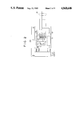
- FIG. 1 is a schematic diagram showing an electronic endoscope system including an image pickup apparatus according to an embodiment of the present invention
- FIG. 2 is an electric circuit diagram showing an example of a solid-state image sensor and a generator circuit for generating drive voltages which constitute the image pickup unit shown in FIG. 1;
- FIG. 3 is a partial circuit diagram showing an example of a drive voltage adjusting device of the drive voltage generator circuit shown in FIG. 2;
- FIG. 4 is a partial circuit diagram showing another example of a drive voltage adjusting device of the drive voltage generator circuit shown in FIG. 2;
- FIG. 5 is an electrical circuit diagram showing a still another example of a drive voltage adjusting device of the drive voltage generator circuit
- FIG. 6 is an electrical circuit diagram showing a further example of a generator circuit for generating drive voltages
- FIG. 7 is an electrical circuit showing a still further example of a generator circuit for generating drive voltages.
- an electronic endosope 1 includes an image pickup unit 20 disposed within the distal end 2 of a flexible insertable portion 3 thereof.
- the proximal end of the insertable portion 3 is connected to an operating portion 4 of the endoscope 1.
- a light guide cord 5 extending from the operating portion 4 is connected to a light source 8.
- a signal cord 6 extending from the operating portion 4 is connected to a signal processor unit 10 by means of a connector 9.
- the front end of an optical fiber bundle 11 used for illumination is disposed at the distal end 2.
- the optical fiber bundle 11 is inserted within the insertable portion 3 and the light guide cord 5 and connected to the light source 8 by means of a connector 7 so as to introduce light rays from the light source 8.
- An objective 12 is disposed at the distal end 2.
- a solid-state image sensor 13 is disposed on an image forming place of the objective 12.
- a circuit substrate 14 (provided with a drive voltage generator circuit) is disposed adjacent to the solid-state image sensor 13.
- the substrate 14 and the connector 9 are connected to each other by means of a pluralilty of signal lines 15 which extend through the insertable portion 3, operating portion 4 and signal cord 6.
- the signal lines 15 are supplied with a variety of voltages and signals from drive circuits 16, 17 within the signal processor unit 10.
- An output signal from the image sensor 13 is supplied to a process circuit 18 within the signal processor unit 10.
- the process circuit 18 converts an output signal from the image sensor 13 to an image video signal which is applied to a display unit 19 connected to the signal processor unit 10.
- FIG. 2 shows the image pickup unit 20 comprising the solid-state image sensor 13 and the drive voltage generator circuit substrate 14.
- a substrate voltage for example, is one of the drive voltages to be adjusted.
- the substrate voltage applied to the terminal V SUB of the solid-state image sensor 13 must be adjusted to a level between 4 and 14 V because of particular image sensor being used. As a practical matter, it is sufficient to adjust the substrate voltages in steps of about 0.5 V.
- a substrate voltage generator 21 is provided on the drive voltage generator circuit substrate 14 together with an adjusting device therefore.
- an emitter follower circuit is formed by a transistor 22 and an emitter resistor 23.
- a base voltage for the transistor 22 is converted into a low impedance as an emitter output to be delivered as the substrate voltage.
- the base voltage of the transistor 22 is pulled up by a resistor 24 to a positive voltage V DD and connected to a plurality of resistors 25, 26, 27 and 28 on the ground potential side thereof. Terminals of the resistors 25 to 28 on their IC sides are connected to pattern electrode 29 on the substrate 14.
- An example of the pattern electrode 29 is shown in FIG. 3, in which the pattern endoscope 29 is partly separated to form an endoscope on the resistor side and a ground electrode.
- the substrate voltage is adjusted by connecting selected resistors 25 to 28 to ground with the others being disconnected (non-conductive condition) or pulled up.
- all contacts a to d are open initially and only contacts to be selected are made conductive by soldering or applying a conductive material across the electrode gap.
- sixteen levels of voltages can be obtained.
- the number of resistors is increased. When the number of resistors is n, 2 n levels of voltages can be obtained.
- FIG. 4 shows another example of a pattern endoscope. All contacts a to d of a pattern endoscope 30 are initially made in a conductive condition and grounded. The voltages are adjusted by disconnecting contacts other than those of resistors to be selected in an open condition.
- FIG. 5 shows still another example of a voltage adjusting device of a substrate voltage generator circuit 21 provided on the drive voltage generator substrate 14.
- the voltage adjusting device adjusts the voltage using bonding wires. Since the substrate voltage generator circuit 21 of this example is constructed in a manner similar to that shown in FIG. 2, like elements are given like reference characters and their description will be omitted.
- the fixation of the substrate voltage generator circuit 21 composed of IC chips on the substrate 14 and the connection of a power supply and signal lines to the generator circuit 21 are performed by a bonding process. Namely, the supply line of a power source voltage V DD and the collector of a transistor 22 are connected by a bonding wire 50 to apply the voltage V DD , a V SUB terminal of applying the substrate voltage and the emitter of the transistor 22 are connected by a bonding wire 51 and a resistor 23 and the ground line are connected by a bonding wire 56.
- a power supply line and signal lines are generally connected to a circuit composed of IC chips by means of bonding wires.
- This method is utilized in this example. Specifically, one end of the plurality of resistors 25 to 28 are connected to respective selected contacts a to d by means of bonding wires 52 to 55. With such structure, the selected contacts a to d are opened or closed by properly rendering the bonding wires 52 to 55 conductive or non-conductive and thus the substrate voltage can be adjusted. With this example, it is possible to reduce the size of the substrate.
- An output gate voltage V OG is another drive voltage which may be adjusted.
- the output gate voltage can be adjusted by an output gate voltage generator circuit 31 and a pattern 32 for selecting resistors in a manner similar to the substrate voltage. Necessary adjustments of other drive voltages can be performed in a similar manner.
- the substrate 14 has a bias generating function for generating other drive voltages required for the solid-state image sensor 13, a dividing function of a single drive voltage into a plurality of drive signals and a buffer function to an output signal, which are not shown in FIG. 5. All these functions are performed with IC structures and there is little problem in space for arranging the IC structures on the substrate 14. In addition, it is possible to realize them using discrete parts, chip parts, printed parts and the like, because of little problem in space.
- FIG. 6 shows a further example of a generator circuit for generating the substrate voltage.
- a generator circuit 21A an emitter follower circuit comprising a transistor 22 and an emitter resistor 23 is similar to the embodiment shown in FIGS. 2 and 5.
- the base of the transistor 22 is pulled up to a positive voltage V DD ⁇ of a power supply by a resistor 33.
- a plurality of resistors 34 to 39 are connected in series on the ground potential sides to be grounded through the resistor 39. Each junction point between resistors 34 to 39 is connected to a respective electrode of selected contacts a to e and one of the contacts a to e is selectively grounded in order to obtain a desired substrate voltage.
- FIG. 7 shows a still further example of a substrate voltage generator circuit.
- a generator circuit 21B shown in FIG. 7 produces a step voltages to be applied to the base of an emitter follower circuit comprising a transistor 22 and an emitter resistor 23 by addition of currents.
- base potentials of transistors 42 to 45 are given by a divided voltage ratio between resistors 40, 41 all of emitter potentials of the transistors 42 to 45 are equal.
- a current which is inverse in proportion to a value of resistor 45 to 49 corresponding to the selected contact a to d flows between collector and emitter of the corresponding transistor 42 to 45. Accordingly, the total sum of the currents flows through a resistor 24.
- values of the resistors 46 to 49 are taken in multiple proportion such as R, 2R, 4R and 8R, 24 levels of output voltages of the emitter follower circuit are produced in equal parts to the number of four contacts.
- While the light source 8 and signal processor unit 10 shown in FIG. 1 are separately provided, it is possible to combine both into a unitary body and contain them in a single case. It will be understood that the present invention is applicable to a variety of other image pickup apparatus in addition an electronic endoscope.
Landscapes
- Engineering & Computer Science (AREA)
- Multimedia (AREA)
- Signal Processing (AREA)
- Transforming Light Signals Into Electric Signals (AREA)
- Endoscopes (AREA)
Abstract
Description
Claims (12)
Applications Claiming Priority (6)
| Application Number | Priority Date | Filing Date | Title |
|---|---|---|---|
| JP8244787 | 1987-04-03 | ||
| JP62-82447 | 1987-04-03 | ||
| JP20983687 | 1987-08-24 | ||
| JP62-209836 | 1987-08-24 | ||
| JP63002241A JPH0671324B2 (en) | 1987-04-03 | 1988-01-08 | Imaging device |
| JP63-2241 | 1988-01-08 |
Publications (1)
| Publication Number | Publication Date |
|---|---|
| US4868646A true US4868646A (en) | 1989-09-19 |
Family
ID=27275260
Family Applications (1)
| Application Number | Title | Priority Date | Filing Date |
|---|---|---|---|
| US07/170,549 Expired - Lifetime US4868646A (en) | 1987-04-03 | 1988-03-21 | Image pickup apparatus for an electronic endoscope |
Country Status (3)
| Country | Link |
|---|---|
| US (1) | US4868646A (en) |
| JP (1) | JPH0671324B2 (en) |
| DE (1) | DE3810295A1 (en) |
Cited By (17)
| Publication number | Priority date | Publication date | Assignee | Title |
|---|---|---|---|---|
| US5087978A (en) * | 1988-09-05 | 1992-02-11 | Canon Kabushiki Kaisha | Camera system and interchangeable lens |
| US5144447A (en) * | 1988-03-31 | 1992-09-01 | Hitachi, Ltd. | Solid-state image array with simultaneously activated line drivers |
| US5220198A (en) * | 1990-08-27 | 1993-06-15 | Olympus Optical Co., Ltd. | Solid state imaging apparatus in which a solid state imaging device chip and substrate are face-bonded with each other |
| US5426515A (en) * | 1992-06-01 | 1995-06-20 | Eastman Kodak Company | Lateral overflow gate driver circuit for linear CCD sensor |
| US5575757A (en) * | 1992-10-09 | 1996-11-19 | Smith & Nephew Endoscopy Inc. | Endoscope with focusing mechanism |
| US5896166A (en) * | 1993-06-02 | 1999-04-20 | Envision Medical Corporation | Remote CCD video camera with non-volatile digital memory |
| US6292090B1 (en) * | 1996-08-30 | 2001-09-18 | Funai Electric Co., Ltd. | Position detecting switch |
| US6468201B1 (en) | 2001-04-27 | 2002-10-22 | Welch Allyn, Inc. | Apparatus using PNP bipolar transistor as buffer to drive video signal |
| US6524235B2 (en) * | 2000-05-22 | 2003-02-25 | Fuji Photo Optical Co., Ltd. | Endoscopic image pickup assembly |
| US20040061776A1 (en) * | 2000-10-10 | 2004-04-01 | Olympus Optical Co., Ltd. | Image pickup system |
| US20060038108A1 (en) * | 2002-12-19 | 2006-02-23 | Siemens Aktiengesellschaft | Image-generation device, in particular for installation in the roof area or exterior rearview mirror of a motor vehicle |
| US20080084487A1 (en) * | 2006-10-10 | 2008-04-10 | Akihiro Yoshida | Imaging apparatus, imaging pickup unit connectable to a lens unit, and a lens unit connectable to imaging pickup unit |
| US20100238278A1 (en) * | 2009-01-27 | 2010-09-23 | Tokendo | Videoendoscopy system |
| US20110025850A1 (en) * | 2009-08-03 | 2011-02-03 | Ricoh Company, Ltd. | Camera unit and sensing device |
| US8213676B2 (en) | 2006-12-20 | 2012-07-03 | Ge Inspection Technologies Lp | Inspection apparatus method and apparatus comprising motion responsive control |
| US8810636B2 (en) | 2006-12-20 | 2014-08-19 | Ge Inspection Technologies, Lp | Inspection apparatus method and apparatus comprising selective frame output |
| US10291850B2 (en) | 2006-12-20 | 2019-05-14 | General Electric Company | Inspection apparatus method and apparatus comprising selective frame output |
Citations (9)
| Publication number | Priority date | Publication date | Assignee | Title |
|---|---|---|---|---|
| US4539586A (en) * | 1983-10-07 | 1985-09-03 | Welch Allyn Inc. | Connector module for video endoscopic system |
| JPS60244161A (en) * | 1984-05-18 | 1985-12-04 | Fuji Photo Optical Co Ltd | Endoscope |
| US4608506A (en) * | 1983-03-31 | 1986-08-26 | Tokyo Shibaura Denki Kabushiki Kaisha | Temperature compensated drive for a piezoelectric displacement generator |
| US4634884A (en) * | 1983-07-12 | 1987-01-06 | Kabushiki Kaisha Toshiba | Swing-driven solid-state image sensor |
| US4663669A (en) * | 1984-02-01 | 1987-05-05 | Canon Kabushiki Kaisha | Image sensing apparatus |
| US4678938A (en) * | 1984-09-28 | 1987-07-07 | Olympus Optical Co., Ltd. | Solid-state image sensing apparatus having an automatic control loop |
| US4692798A (en) * | 1984-01-09 | 1987-09-08 | Nissan Motor Company, Limited | Apparatus and process for improving visibility of object within visual field |
| US4712138A (en) * | 1984-12-28 | 1987-12-08 | Canon Kabushiki Kaisha | Low-noise apparatus for image pickup and combination of light and electric signals |
| US4746984A (en) * | 1985-04-24 | 1988-05-24 | Olympus Optical Co., Ltd. | Solid state image sensor with lateral-type stactic induction transistors |
Family Cites Families (2)
| Publication number | Priority date | Publication date | Assignee | Title |
|---|---|---|---|---|
| JPS61164379A (en) * | 1985-01-17 | 1986-07-25 | Matsushita Electric Ind Co Ltd | Camera system |
| US4803562A (en) * | 1986-06-20 | 1989-02-07 | Olympus Optical Co., Ltd. | Image sensing apparatus |
-
1988
- 1988-01-08 JP JP63002241A patent/JPH0671324B2/en not_active Expired - Fee Related
- 1988-03-21 US US07/170,549 patent/US4868646A/en not_active Expired - Lifetime
- 1988-03-25 DE DE3810295A patent/DE3810295A1/en active Granted
Patent Citations (11)
| Publication number | Priority date | Publication date | Assignee | Title |
|---|---|---|---|---|
| US4608506A (en) * | 1983-03-31 | 1986-08-26 | Tokyo Shibaura Denki Kabushiki Kaisha | Temperature compensated drive for a piezoelectric displacement generator |
| US4634884A (en) * | 1983-07-12 | 1987-01-06 | Kabushiki Kaisha Toshiba | Swing-driven solid-state image sensor |
| US4539586A (en) * | 1983-10-07 | 1985-09-03 | Welch Allyn Inc. | Connector module for video endoscopic system |
| US4539586B1 (en) * | 1983-10-07 | 1991-12-17 | Welch Allyn Inc | |
| US4692798A (en) * | 1984-01-09 | 1987-09-08 | Nissan Motor Company, Limited | Apparatus and process for improving visibility of object within visual field |
| US4663669A (en) * | 1984-02-01 | 1987-05-05 | Canon Kabushiki Kaisha | Image sensing apparatus |
| JPS60244161A (en) * | 1984-05-18 | 1985-12-04 | Fuji Photo Optical Co Ltd | Endoscope |
| US4667230A (en) * | 1984-05-18 | 1987-05-19 | Fuji Photo Optical Co., Ltd. | Endoscope having a control section with level adjusting device |
| US4678938A (en) * | 1984-09-28 | 1987-07-07 | Olympus Optical Co., Ltd. | Solid-state image sensing apparatus having an automatic control loop |
| US4712138A (en) * | 1984-12-28 | 1987-12-08 | Canon Kabushiki Kaisha | Low-noise apparatus for image pickup and combination of light and electric signals |
| US4746984A (en) * | 1985-04-24 | 1988-05-24 | Olympus Optical Co., Ltd. | Solid state image sensor with lateral-type stactic induction transistors |
Cited By (28)
| Publication number | Priority date | Publication date | Assignee | Title |
|---|---|---|---|---|
| US5144447A (en) * | 1988-03-31 | 1992-09-01 | Hitachi, Ltd. | Solid-state image array with simultaneously activated line drivers |
| US5087978A (en) * | 1988-09-05 | 1992-02-11 | Canon Kabushiki Kaisha | Camera system and interchangeable lens |
| US5220198A (en) * | 1990-08-27 | 1993-06-15 | Olympus Optical Co., Ltd. | Solid state imaging apparatus in which a solid state imaging device chip and substrate are face-bonded with each other |
| US5426515A (en) * | 1992-06-01 | 1995-06-20 | Eastman Kodak Company | Lateral overflow gate driver circuit for linear CCD sensor |
| US5575757A (en) * | 1992-10-09 | 1996-11-19 | Smith & Nephew Endoscopy Inc. | Endoscope with focusing mechanism |
| US5896166A (en) * | 1993-06-02 | 1999-04-20 | Envision Medical Corporation | Remote CCD video camera with non-volatile digital memory |
| US6313868B1 (en) | 1993-06-02 | 2001-11-06 | Linvatec Corporation | Remote CCD video camera with non-volatile digital memory |
| US6292090B1 (en) * | 1996-08-30 | 2001-09-18 | Funai Electric Co., Ltd. | Position detecting switch |
| US6524235B2 (en) * | 2000-05-22 | 2003-02-25 | Fuji Photo Optical Co., Ltd. | Endoscopic image pickup assembly |
| US7821529B2 (en) * | 2000-10-10 | 2010-10-26 | Olympus Corporation | Image pickup system |
| US20040061776A1 (en) * | 2000-10-10 | 2004-04-01 | Olympus Optical Co., Ltd. | Image pickup system |
| US6468201B1 (en) | 2001-04-27 | 2002-10-22 | Welch Allyn, Inc. | Apparatus using PNP bipolar transistor as buffer to drive video signal |
| US7208716B2 (en) | 2002-12-19 | 2007-04-24 | Siemens Aktiengesellschaft | Image-generation device, in particular for installation in the roof area or exterior rearview mirror of a motor vehicle |
| US20060038108A1 (en) * | 2002-12-19 | 2006-02-23 | Siemens Aktiengesellschaft | Image-generation device, in particular for installation in the roof area or exterior rearview mirror of a motor vehicle |
| US20080084487A1 (en) * | 2006-10-10 | 2008-04-10 | Akihiro Yoshida | Imaging apparatus, imaging pickup unit connectable to a lens unit, and a lens unit connectable to imaging pickup unit |
| US8045010B2 (en) * | 2006-10-10 | 2011-10-25 | Ricoh Company, Ltd | Imaging apparatus, imaging pickup unit connectable to a lens unit, and a lens unit connectable to imaging pickup unit |
| US8810636B2 (en) | 2006-12-20 | 2014-08-19 | Ge Inspection Technologies, Lp | Inspection apparatus method and apparatus comprising selective frame output |
| US8213676B2 (en) | 2006-12-20 | 2012-07-03 | Ge Inspection Technologies Lp | Inspection apparatus method and apparatus comprising motion responsive control |
| US9621808B2 (en) | 2006-12-20 | 2017-04-11 | General Electric Company | Inspection apparatus method and apparatus comprising selective frame output |
| US10291850B2 (en) | 2006-12-20 | 2019-05-14 | General Electric Company | Inspection apparatus method and apparatus comprising selective frame output |
| US20100238278A1 (en) * | 2009-01-27 | 2010-09-23 | Tokendo | Videoendoscopy system |
| US20110025850A1 (en) * | 2009-08-03 | 2011-02-03 | Ricoh Company, Ltd. | Camera unit and sensing device |
| US8681220B2 (en) * | 2009-08-03 | 2014-03-25 | Ricoh Company, Ltd. | Camera unit and sensing device |
| US20140146227A1 (en) * | 2009-08-03 | 2014-05-29 | Ricoh Company, Ltd. | Camera unit and sensing device |
| US9369613B2 (en) * | 2009-08-03 | 2016-06-14 | Ricoh Company, Ltd. | Camera unit and sensing device |
| US20160286162A1 (en) * | 2009-08-03 | 2016-09-29 | Ricoh Company, Ltd. | Camera unit and sensing device |
| US9813665B2 (en) * | 2009-08-03 | 2017-11-07 | Ricoh Company, Ltd. | Camera unit and sensing device |
| US10277863B2 (en) * | 2009-08-03 | 2019-04-30 | Ricoh Company, Ltd. | Camera unit and sensing device |
Also Published As
| Publication number | Publication date |
|---|---|
| DE3810295A1 (en) | 1988-10-20 |
| JPH0671324B2 (en) | 1994-09-07 |
| JPH01198876A (en) | 1989-08-10 |
Similar Documents
| Publication | Publication Date | Title |
|---|---|---|
| US4868646A (en) | Image pickup apparatus for an electronic endoscope | |
| US4867137A (en) | Electronic endoscope | |
| US4831456A (en) | Imaging apparatus using a solid-state imaging element having a substrate | |
| US4074306A (en) | Endoscope utilizing color television and fiber optics techniques | |
| JPH012622A (en) | electronic endoscope | |
| US4998182A (en) | Connector for optical sensor | |
| US4667230A (en) | Endoscope having a control section with level adjusting device | |
| US6468201B1 (en) | Apparatus using PNP bipolar transistor as buffer to drive video signal | |
| US6006298A (en) | On-line module replacement system | |
| US20230103993A1 (en) | Imaging apparatus and electronic equipment | |
| DE2633742C2 (en) | endoscope | |
| US5030896A (en) | D.C. restore for a remote video interconnect | |
| JPH01198182A (en) | Image pickup device | |
| US4488085A (en) | Image pick-up tube arrangement | |
| JP3270047B2 (en) | Vertical deflection circuit device | |
| JP4018941B2 (en) | Signal interference prevention unit and signal processing apparatus | |
| JP2001027734A (en) | Image pickup unit | |
| JPH06104101B2 (en) | Imaging device | |
| JPH02168928A (en) | Electron endoscope device | |
| JP3207229B2 (en) | Signal transmission processing circuit of electronic endoscope device | |
| JPH01136627A (en) | Endoscopic apparatus | |
| WO2020003615A1 (en) | Endoscope | |
| JPH10262919A (en) | Electronic endoscope equipment | |
| EP0413646B1 (en) | A gain control device for a video monitor | |
| JPS61287383A (en) | Image pickup device |
Legal Events
| Date | Code | Title | Description |
|---|---|---|---|
| AS | Assignment |
Owner name: OLYMPUS OPTICAL COMPANY LTD., 43-2, 2-CHOME, HATAG Free format text: ASSIGNMENT OF ASSIGNORS INTEREST.;ASSIGNOR:TSUJI, KIYOSHI;REEL/FRAME:004862/0706 Effective date: 19880301 Owner name: OLYMPUS OPTICAL COMPANY LTD., A JAPANESE CORP., JA Free format text: ASSIGNMENT OF ASSIGNORS INTEREST;ASSIGNOR:TSUJI, KIYOSHI;REEL/FRAME:004862/0706 Effective date: 19880301 |
|
| STCF | Information on status: patent grant |
Free format text: PATENTED CASE |
|
| FEPP | Fee payment procedure |
Free format text: PAYOR NUMBER ASSIGNED (ORIGINAL EVENT CODE: ASPN); ENTITY STATUS OF PATENT OWNER: LARGE ENTITY |
|
| FPAY | Fee payment |
Year of fee payment: 4 |
|
| FEPP | Fee payment procedure |
Free format text: PAYOR NUMBER ASSIGNED (ORIGINAL EVENT CODE: ASPN); ENTITY STATUS OF PATENT OWNER: LARGE ENTITY Free format text: PAYER NUMBER DE-ASSIGNED (ORIGINAL EVENT CODE: RMPN); ENTITY STATUS OF PATENT OWNER: LARGE ENTITY |
|
| FPAY | Fee payment |
Year of fee payment: 8 |
|
| FPAY | Fee payment |
Year of fee payment: 12 |