US4858424A - Variable radius cable carrier - Google Patents
Variable radius cable carrier Download PDFInfo
- Publication number
- US4858424A US4858424A US07/232,163 US23216388A US4858424A US 4858424 A US4858424 A US 4858424A US 23216388 A US23216388 A US 23216388A US 4858424 A US4858424 A US 4858424A
- Authority
- US
- United States
- Prior art keywords
- links
- link
- curvature
- carrier
- conductor
- Prior art date
- Legal status (The legal status is an assumption and is not a legal conclusion. Google has not performed a legal analysis and makes no representation as to the accuracy of the status listed.)
- Expired - Lifetime
Links
Images

Classifications
-
- H—ELECTRICITY
- H02—GENERATION; CONVERSION OR DISTRIBUTION OF ELECTRIC POWER
- H02G—INSTALLATION OF ELECTRIC CABLES OR LINES, OR OF COMBINED OPTICAL AND ELECTRIC CABLES OR LINES
- H02G11/00—Arrangements of electric cables or lines between relatively-movable parts
- H02G11/006—Arrangements of electric cables or lines between relatively-movable parts using extensible carrier for the cable, e.g. self-coiling spring
-
- F—MECHANICAL ENGINEERING; LIGHTING; HEATING; WEAPONS; BLASTING
- F16—ENGINEERING ELEMENTS AND UNITS; GENERAL MEASURES FOR PRODUCING AND MAINTAINING EFFECTIVE FUNCTIONING OF MACHINES OR INSTALLATIONS; THERMAL INSULATION IN GENERAL
- F16G—BELTS, CABLES, OR ROPES, PREDOMINANTLY USED FOR DRIVING PURPOSES; CHAINS; FITTINGS PREDOMINANTLY USED THEREFOR
- F16G13/00—Chains
- F16G13/12—Hauling- or hoisting-chains so called ornamental chains
- F16G13/16—Hauling- or hoisting-chains so called ornamental chains with arrangements for holding electric cables, hoses, or the like
Definitions
- the subject invention relates to a rolling cable/conductor carrier used to protect, support and guide electric or hydraulic lines connected between a stationary point and a movable piece of machinery.
- This radius of curvature is mechanically determined by the structure of the carrier, and is not variable except by substitution or modification of parts during assembly.
- One prior art technique for defining the radius of curvature involves the formation of a kidney-shaped slot in one of the links of each chain and the disposition in this slot of a pin carried by the overlapping link.
- the length of the slot determines the minimum radius of curvature for the carrier.
- a longer slot results in a smaller radius of curvature.
- the invention is a unique link assembly allowing for the construction of a cable/conductor carrier with multiple radii of curvature, anyone of which may be selected during assembly without changing or substituting for the elements that comprise the carrier.
- the invention comprises a plate-link chain having pivotally connected overlapping inner and outer links wherein several arcuate slots of different lengths are located concentrically about the pivot point on the inner link, and a slug pin which extends through a selected one of the arcuate slots and is retained by the outer link thereby limiting the maximum angular relationship between the links.
- a preferred commercial embodiment of the invention comprises a serpentine, box-like structure of two "chains" which, like the prior art devices, are interconnected in parallel by bridging pins and which consist of pivotally connected inner and outer links.
- the inner links in each chain exhibit a plurality of slots arrayed about a common center, each slot in the arrangement having a different length representing a different, selectable minimum carrier radius curvature.
- Small pins hereinafter called slugs, are placed during assembly in the desired slots and are captured by recess or pockets formed integrally in outer links which are pivotally connected to the inner links.
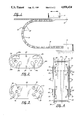
- FIG. 1 is a side view of the rolling conductor support of the present invention connected between a stationary point and a movable piece of machinery;
- FIG. 2 is a side view of an inner link
- FIG. 3 is a side view of an outer link
- FIG. 4 is a top view of a portion of the conductor assembly as shown in FIG. 1;
- FIG. 5 is an exploded perspective view of the linkage assembly
- FIG. 6 is a side view in which the two links are disposed in an angular position wherein the pin restricts the rotational movement;
- FIG. 7 is a side view similar to FIG. 6 in which the two links are disposed in an intermediate angular position
- FIG. 8 is a side view similar to FIGS. 6 and 7 in which the two links are disposed in the most restrictive angular position.
- FIG. 1 shows an illustrative installation of a rolling cable/conductor carrier 10 attached at one end to a moving piece of machinery 16 operating on a set of rails or guides 14 and attached at the other end to a stationary piece of machinery 12 resting on the floor 18 or or a support member.
- the cable/conductor carrier 10 consists of a pair of narrowly spaced parallel chains consisting of inner links 20 and outer links 22.
- FIG. 2 shows an inner link 20 substantially rectangular in shape having circular ends.
- Central apertures 24 adapted to receive pivot pins 40 are located at each end of the inner link 20 along a horizontal longitudinal center line.
- Three arcuate slots 26A, 26B and 26C of different lengths are arranged concentrically about the central aperture 24. When one of these is combined with a stop pin or slug 38, the arcuate slot 26A, 26B, 26C limits the rotation about the central aperture 24 as hereinafter described.
- the inner link 20 also contains two transverse holes 28 which are adapted to receive the support rods 34 which bridge the parallel link assemblies and are the support means for the cables or conductors.
- FIG. 3 shows an outer link 22 of substantially rectangular shape with semi-circular ends having a longitudinal center line extending in the horizontal direction about which two central apertures 30 are located.
- Arranged concentrically about the central aperture 30 are three stamped or forged pockets 32 extending outward and perpendicular from the planar outer surface of the outer link 22. These indentations 32 are adapted to receive and retain a stop pin or slug 38.
- FIG. 5 shows an exploded view of the linkage assembly.
- the preferred embodiment comprises an inner link 20 placed between two outer links 22, the links are connected at the respective central apertures using a pin 40 retained by a snap ring 42.
- a stop pin 38 is inserted into a selected arcuate slot 26A, and is received on both ends by the indentations 32 of the outer link 22.
- the pin 38 is not connected to the outer link 22 but is instead free floating and held in place by the pockets 32 of the outer link 22.
- the assembler need only remove the snap ring 42, enabling removal of an outer link 22 allowing the assembler to reposition the stop pin or slug 38 in a different arcuate slot 26B, 26C.
- the repositioning of the stop pin 38 is the means allowing a different radius of curvature to be obtained.
- FIG. 4 shows a top view of the conductor support illustrating the combination of inner 20 and outer 22 links connected by the support rods 34 used to contain the cables or conductors 36.
- each inner link 20 is connected with two separate outer links 22.
- the outer links 22 contain the .cp4 stop pin 38, which also extends through the inner link 20 between them.
- FIGS. 6, 7 and 8 show an illustrative example of the radius of curvature than can be obtained when the stop pin 38 is placed in one of the arcuate slots 26A, 26B, 26C of the inner link 20.
- the longer the arcuate slot 26A that the stop pin or slug 38 is placed in the smaller the radius of curvature.
- the radius of curvature will then be placed at a maximum.
- the radius of curvature of the cable/conductor carrier 10 can be varied by the assembler using the same elements, simply by varying the installed position of slug 38.
- the assembler need only move the stop pin or slug 38 to a different arcuate slot 26A, 26B, 26C to allow a change in the radius of curvature.
- This forms an improvement in that added parts are not needed to vary the conductor radius.
- a more economical rolling support is created allowing for a reduction in inventory and cost of manufacturing.
Landscapes
- Engineering & Computer Science (AREA)
- General Engineering & Computer Science (AREA)
- Mechanical Engineering (AREA)
- Electric Cable Arrangement Between Relatively Moving Parts (AREA)
Abstract
Description
Claims (3)
Priority Applications (4)
| Application Number | Priority Date | Filing Date | Title |
|---|---|---|---|
| US07/232,163 US4858424A (en) | 1988-08-15 | 1988-08-15 | Variable radius cable carrier |
| CA000584033A CA1296696C (en) | 1988-08-15 | 1988-11-24 | Variable radius cable carrier |
| EP19890908024 EP0381723A4 (en) | 1988-08-15 | 1989-06-06 | Variable radius cable carrier |
| PCT/US1989/002463 WO1990001646A1 (en) | 1988-08-15 | 1989-06-06 | Variable radius cable carrier |
Applications Claiming Priority (1)
| Application Number | Priority Date | Filing Date | Title |
|---|---|---|---|
| US07/232,163 US4858424A (en) | 1988-08-15 | 1988-08-15 | Variable radius cable carrier |
Publications (1)
| Publication Number | Publication Date |
|---|---|
| US4858424A true US4858424A (en) | 1989-08-22 |
Family
ID=22872119
Family Applications (1)
| Application Number | Title | Priority Date | Filing Date |
|---|---|---|---|
| US07/232,163 Expired - Lifetime US4858424A (en) | 1988-08-15 | 1988-08-15 | Variable radius cable carrier |
Country Status (4)
| Country | Link |
|---|---|
| US (1) | US4858424A (en) |
| EP (1) | EP0381723A4 (en) |
| CA (1) | CA1296696C (en) |
| WO (1) | WO1990001646A1 (en) |
Cited By (11)
| Publication number | Priority date | Publication date | Assignee | Title |
|---|---|---|---|---|
| US5048283A (en) * | 1989-08-26 | 1991-09-17 | Kabelschlepp Gesellschaft Mit Beschrankter Haftung | Guide chain for guiding energy lines |
| EP0494670A1 (en) * | 1991-01-09 | 1992-07-15 | Shimano Inc. | Bicycle chain |
| DE19512088A1 (en) * | 1995-04-03 | 1996-10-10 | Igus Gmbh | Energy chain |
| US6356696B1 (en) | 2000-02-23 | 2002-03-12 | Delphi Technologies, Inc. | Radius control rod |
| AU776391B2 (en) * | 1999-08-11 | 2004-09-09 | Callaway Golf Company | Golf ball with soft core |
| US20060257093A1 (en) * | 2003-11-05 | 2006-11-16 | Advantest Corporation | Test apparatus and cable guide unit |
| US7234292B1 (en) | 2003-11-13 | 2007-06-26 | A&A Manufacturing Co., Inc. | Cable and hose carrier support system |
| US20070234701A1 (en) * | 2006-04-11 | 2007-10-11 | Christine Heppner | Power transmission chain made from metal |
| KR100876640B1 (en) | 2008-01-12 | 2009-01-07 | 주식회사 코닥트 | Cableveyor |
| JP2017081253A (en) * | 2015-10-23 | 2017-05-18 | 株式会社ダイフク | Car washing machine |
| CN111503223A (en) * | 2020-03-18 | 2020-08-07 | 江山市王牌链业有限公司 | Novel anti-blocking chain group structure |
Citations (2)
| Publication number | Priority date | Publication date | Assignee | Title |
|---|---|---|---|---|
| GB1075974A (en) * | 1965-05-18 | 1967-07-19 | Stuas Stanzwerk Und App Bau Si | Link chain, which can be buckled only in one transverse direction from its stretched condition |
| US4625507A (en) * | 1984-02-28 | 1986-12-02 | Kabelschlepp Gesellschaft Mit Beschrankter Haftung | Guide chain |
Family Cites Families (5)
| Publication number | Priority date | Publication date | Assignee | Title |
|---|---|---|---|---|
| DE1267918B (en) * | 1965-10-20 | 1968-05-09 | O L M A T S P A | Chain link for guiding material, in particular pipes, electrical cables or the like. |
| US3716986A (en) * | 1970-10-21 | 1973-02-20 | Gemco Electric Co | Rolling conductor support |
| US3782670A (en) * | 1972-02-10 | 1974-01-01 | A & A Mfg Co Inc | Carrier link mechanism for flexible supply lines |
| DE2360227C3 (en) * | 1973-12-04 | 1981-08-20 | Kabelschlepp Gmbh, 5900 Siegen | Energy chain |
| US4590961A (en) * | 1985-08-16 | 1986-05-27 | Cooper Industries, Inc. | Modular rolling conductor support |
-
1988
- 1988-08-15 US US07/232,163 patent/US4858424A/en not_active Expired - Lifetime
- 1988-11-24 CA CA000584033A patent/CA1296696C/en not_active Expired - Lifetime
-
1989
- 1989-06-06 EP EP19890908024 patent/EP0381723A4/en not_active Withdrawn
- 1989-06-06 WO PCT/US1989/002463 patent/WO1990001646A1/en not_active Application Discontinuation
Patent Citations (2)
| Publication number | Priority date | Publication date | Assignee | Title |
|---|---|---|---|---|
| GB1075974A (en) * | 1965-05-18 | 1967-07-19 | Stuas Stanzwerk Und App Bau Si | Link chain, which can be buckled only in one transverse direction from its stretched condition |
| US4625507A (en) * | 1984-02-28 | 1986-12-02 | Kabelschlepp Gesellschaft Mit Beschrankter Haftung | Guide chain |
Cited By (20)
| Publication number | Priority date | Publication date | Assignee | Title |
|---|---|---|---|---|
| US5048283A (en) * | 1989-08-26 | 1991-09-17 | Kabelschlepp Gesellschaft Mit Beschrankter Haftung | Guide chain for guiding energy lines |
| EP0494670A1 (en) * | 1991-01-09 | 1992-07-15 | Shimano Inc. | Bicycle chain |
| US5288278A (en) * | 1991-01-09 | 1994-02-22 | Shimano Inc. | Bicycle chain |
| DE19512088A1 (en) * | 1995-04-03 | 1996-10-10 | Igus Gmbh | Energy chain |
| US5890357A (en) * | 1995-04-03 | 1999-04-06 | Igus Spritzgubteile Fur Die Industrie Gmbh | Chain-type casing |
| AU776391B2 (en) * | 1999-08-11 | 2004-09-09 | Callaway Golf Company | Golf ball with soft core |
| US6356696B1 (en) | 2000-02-23 | 2002-03-12 | Delphi Technologies, Inc. | Radius control rod |
| US7286742B2 (en) * | 2003-11-05 | 2007-10-23 | Advantest Corporation | Test apparatus and cable guide unit |
| US20060257093A1 (en) * | 2003-11-05 | 2006-11-16 | Advantest Corporation | Test apparatus and cable guide unit |
| US20070258694A1 (en) * | 2003-11-05 | 2007-11-08 | Advantest Corporation | Test apparatus and cable guide unit |
| US7349617B2 (en) * | 2003-11-05 | 2008-03-25 | Advantest Corporation | Test apparatus and cable guide unit |
| US7234292B1 (en) | 2003-11-13 | 2007-06-26 | A&A Manufacturing Co., Inc. | Cable and hose carrier support system |
| US20070234701A1 (en) * | 2006-04-11 | 2007-10-11 | Christine Heppner | Power transmission chain made from metal |
| US7877978B2 (en) * | 2006-04-11 | 2011-02-01 | Kabelschlepp Gmbh | Power transmission chain made from metal |
| CN101421537B (en) * | 2006-04-11 | 2012-03-21 | 缆线牵引有限公司 | Power transmission chain made from metal |
| TWI395893B (en) * | 2006-04-11 | 2013-05-11 | Tsubaki Kabelschlepp GmbH | Power transmission chain made from metal |
| KR100876640B1 (en) | 2008-01-12 | 2009-01-07 | 주식회사 코닥트 | Cableveyor |
| JP2017081253A (en) * | 2015-10-23 | 2017-05-18 | 株式会社ダイフク | Car washing machine |
| CN111503223A (en) * | 2020-03-18 | 2020-08-07 | 江山市王牌链业有限公司 | Novel anti-blocking chain group structure |
| CN111503223B (en) * | 2020-03-18 | 2022-10-11 | 江山市王牌链业有限公司 | Anti-blocking chain group structure |
Also Published As
| Publication number | Publication date |
|---|---|
| EP0381723A4 (en) | 1990-09-26 |
| WO1990001646A1 (en) | 1990-02-22 |
| CA1296696C (en) | 1992-03-03 |
| EP0381723A1 (en) | 1990-08-16 |
Similar Documents
| Publication | Publication Date | Title |
|---|---|---|
| US4858424A (en) | Variable radius cable carrier | |
| US4311293A (en) | Rolling conductor supports | |
| KR100630522B1 (en) | Line guidance device | |
| RU2160399C2 (en) | Guiding chain for power lines | |
| CA1302940C (en) | Flat wire conveyor with differential pitch | |
| KR970068074A (en) | Telecommunication cable management device | |
| US3716986A (en) | Rolling conductor support | |
| EP0753900A1 (en) | Terminal and cramping connector | |
| US6423901B2 (en) | Guiding arrangement for energy lines | |
| EP1619695B1 (en) | A UTP cable assembly having means for preventing cross talk | |
| EP1119077A1 (en) | Contact element for electrically connecting two contact pieces | |
| JP2728125B2 (en) | Contact | |
| EP0109780A1 (en) | Improved power transmission chain | |
| EP0787664A1 (en) | Conveyor pin retention system using offset openings | |
| US4499720A (en) | Cable carrier | |
| JPH10510905A (en) | Energy guide chain | |
| US7195116B2 (en) | Link chain | |
| KR100377842B1 (en) | Power supply chain | |
| US4891039A (en) | Power transmitting V-belt | |
| US4986798A (en) | Transmission chain with pivot pins and intermediate pieces with rolling contact action | |
| JP2616959B2 (en) | Endless transmission belt | |
| AU722805B2 (en) | A low noise belt for continuously variable transmission | |
| JPH01275930A (en) | Link and driving belt | |
| KR920008460A (en) | Ammunition loading system | |
| US4915673A (en) | Variable diameter pulley having extendible elements |
Legal Events
| Date | Code | Title | Description |
|---|---|---|---|
| AS | Assignment |
Owner name: MAGNETEK CONTROLS, 1080 N. CROOKS, CLAWSON, MI A C Free format text: ASSIGNMENT OF ASSIGNORS INTEREST.;ASSIGNORS:LODING, DAVID C.;ERNST, JAMES D.;REEL/FRAME:004922/0399 Effective date: 19880801 Owner name: MAGNETEK CONTROLS, A CORP. OF DE.,MICHIGAN Free format text: ASSIGNMENT OF ASSIGNORS INTEREST;ASSIGNORS:LODING, DAVID C.;ERNST, JAMES D.;REEL/FRAME:004922/0399 Effective date: 19880801 |
|
| FEPP | Fee payment procedure |
Free format text: PAYOR NUMBER ASSIGNED (ORIGINAL EVENT CODE: ASPN); ENTITY STATUS OF PATENT OWNER: LARGE ENTITY |
|
| STCF | Information on status: patent grant |
Free format text: PATENTED CASE |
|
| FPAY | Fee payment |
Year of fee payment: 4 |
|
| AS | Assignment |
Owner name: CHASE MANHATTAN BANK, THE, NEW YORK Free format text: ASSIGNMENT OF ASSIGNORS INTEREST;ASSIGNOR:MICHIGAN ACQUISITION CORPORATION;REEL/FRAME:007097/0968 Effective date: 19940720 |
|
| AS | Assignment |
Owner name: PATRIOT SENSORS & CONTROLS CORPORATION, MICHIGAN Free format text: ASSIGNMENT OF ASSIGNORS INTEREST;ASSIGNOR:MAGNETEK, INC.;REEL/FRAME:007149/0278 Effective date: 19940720 |
|
| AS | Assignment |
Owner name: JACKSON NAT'L LIFE INSURANCE COMPANY, ILLINOIS Free format text: SECURITY INTEREST;ASSIGNOR:PATRIOT SENSORS & CONTROLS CORPORATION;REEL/FRAME:007226/0372 Effective date: 19941025 |
|
| AS | Assignment |
Owner name: PATRIOT SENSORS & CONTROLS CORP., MICHIGAN Free format text: RELEASE BY SECURED PARTY;ASSIGNOR:CHASE MANHATTAN BANK, THE;REEL/FRAME:007308/0445 Effective date: 19941025 |
|
| FPAY | Fee payment |
Year of fee payment: 8 |
|
| FPAY | Fee payment |
Year of fee payment: 12 |