US4856812A - Axle suspension system - Google Patents
Axle suspension system Download PDFInfo
- Publication number
- US4856812A US4856812A US07/175,747 US17574788A US4856812A US 4856812 A US4856812 A US 4856812A US 17574788 A US17574788 A US 17574788A US 4856812 A US4856812 A US 4856812A
- Authority
- US
- United States
- Prior art keywords
- frame
- suspension system
- coupled
- air bag
- air
- Prior art date
- Legal status (The legal status is an assumption and is not a legal conclusion. Google has not performed a legal analysis and makes no representation as to the accuracy of the status listed.)
- Expired - Lifetime
Links
Images

Classifications
-
- B—PERFORMING OPERATIONS; TRANSPORTING
- B60—VEHICLES IN GENERAL
- B60G—VEHICLE SUSPENSION ARRANGEMENTS
- B60G11/00—Resilient suspensions characterised by arrangement, location or kind of springs
- B60G11/26—Resilient suspensions characterised by arrangement, location or kind of springs having fluid springs only, e.g. hydropneumatic springs
- B60G11/27—Resilient suspensions characterised by arrangement, location or kind of springs having fluid springs only, e.g. hydropneumatic springs wherein the fluid is a gas
-
- B—PERFORMING OPERATIONS; TRANSPORTING
- B60—VEHICLES IN GENERAL
- B60G—VEHICLE SUSPENSION ARRANGEMENTS
- B60G13/00—Resilient suspensions characterised by arrangement, location or type of vibration dampers
- B60G13/02—Resilient suspensions characterised by arrangement, location or type of vibration dampers having dampers dissipating energy, e.g. frictionally
- B60G13/06—Resilient suspensions characterised by arrangement, location or type of vibration dampers having dampers dissipating energy, e.g. frictionally of fluid type
- B60G13/10—Resilient suspensions characterised by arrangement, location or type of vibration dampers having dampers dissipating energy, e.g. frictionally of fluid type pneumatic
-
- B—PERFORMING OPERATIONS; TRANSPORTING
- B60—VEHICLES IN GENERAL
- B60G—VEHICLE SUSPENSION ARRANGEMENTS
- B60G21/00—Interconnection systems for two or more resiliently-suspended wheels, e.g. for stabilising a vehicle body with respect to acceleration, deceleration or centrifugal forces
- B60G21/02—Interconnection systems for two or more resiliently-suspended wheels, e.g. for stabilising a vehicle body with respect to acceleration, deceleration or centrifugal forces permanently interconnected
- B60G21/04—Interconnection systems for two or more resiliently-suspended wheels, e.g. for stabilising a vehicle body with respect to acceleration, deceleration or centrifugal forces permanently interconnected mechanically
- B60G21/05—Interconnection systems for two or more resiliently-suspended wheels, e.g. for stabilising a vehicle body with respect to acceleration, deceleration or centrifugal forces permanently interconnected mechanically between wheels on the same axle but on different sides of the vehicle, i.e. the left and right wheel suspensions being interconnected
-
- B—PERFORMING OPERATIONS; TRANSPORTING
- B60—VEHICLES IN GENERAL
- B60G—VEHICLE SUSPENSION ARRANGEMENTS
- B60G7/00—Pivoted suspension arms; Accessories thereof
-
- B—PERFORMING OPERATIONS; TRANSPORTING
- B60—VEHICLES IN GENERAL
- B60G—VEHICLE SUSPENSION ARRANGEMENTS
- B60G7/00—Pivoted suspension arms; Accessories thereof
- B60G7/04—Buffer means for limiting movement of arms
-
- B—PERFORMING OPERATIONS; TRANSPORTING
- B60—VEHICLES IN GENERAL
- B60G—VEHICLE SUSPENSION ARRANGEMENTS
- B60G2202/00—Indexing codes relating to the type of spring, damper or actuator
- B60G2202/10—Type of spring
- B60G2202/15—Fluid spring
- B60G2202/152—Pneumatic spring
- B60G2202/1524—Pneumatic spring with two air springs per wheel, arranged before and after the wheel axis
Definitions
- This invention relates to an axle suspension system, and more particularly, to a suspension system having air bags coupled to a beam between the frame and the axle to provide a soft ride and a large stiffness in the roll.
- the driver of a vehicle prefers to drive a vehicle which has a soft ride.
- the driver also prefers a vehicle that is stiff in roll.
- the vehicle may encounter road conditions, such as bumps, that a soft ride in the suspension will accommodate, but since the vehicle is also required to turn, stiffness in the roll of a vehicle is needed.
- Trucks are particularly sensitive to the stiffness in the roll.
- suspension systems have been interposed between the wheels and the frame of the vehicle to improve the ride.
- One suspension system uses leaf springs.
- the leaf springs usually a plurality of leaves arranged in a stack, cannot provide both a soft ride and large roll stiffness.
- One method of providing a soft ride has been to place an air bag between the axle and the frame to absorb some of the bumps.
- a disadvantage of using air bags is that they are very flexible in the horizontal dimension and they are very soft, that is, they have a low spring rate, which makes the vehicle soft in roll.
- a vehicle suspension system having a member or beam directly coupled to an axle.
- One end of the member is pivotally coupled to the frame, and the other end is coupled to the frame in such a way as to permit vertical displacement but not horizontal displacement at this end of the member.
- Two air bags are mounted on the member, one on either side of the axle.
- One air bag is mounted farther from the pivot point than the other air bag.
- Air lines couple the interior of the air bags to each other to permit air to flow between the bags.
- a restriction is placed in the line to restrict the flow of air between the air bags to provide damping. The amount of restriction is selected to provide damping at a selected frequency, such as the natural frequency of the system.
- the beam is pivotally coupled to the frame at a first end using any well-known pivotal coupling.
- the beam is coupled to the frame at a second end using two shackles.
- the two shackles restrict side movement of the beam but permit full freedom of movement in the vertical and fore-aft horizontal direction. This is accomplished by providing a first shackle pivotally coupled to the second end of the beam.
- a second shackle is pivotally coupled to the first shackle and to the frame.
- the second shackle is also coupled to the frame at a point well behind the second end of the beam.
- the first shackle therefore extends horizontally beyond the second end of the beam. This acts to extend the effective length of the beam.
- the first and second shackles are sufficiently long that full vertical motion by the beam is permitted.
- the first shackle extends behind the beam to ensure freedom of vertical movement through the entire expected range.
- the beam coupled between the axle and the frame is a single beam that is relatively inflexible.
- This type of beam provides stiffness against roll for the vehicle in a turn.
- the beam is mounted to be substantially non-weight-bearing at each end.
- the air bags transfer substantially all the weight of the vehicle from the frame to the axle. This provides long life of the beam and suspension parts.
- the first shackle has an arm that acts as a safety stop to prevent the beam from exceeding a predetermined vertical displacement from the frame.
- a safety stop is provided behind the second shackle to prevent the beam from exceeding a predetermined horizontal displacement.
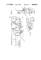
- FIG. 1 is side elevation of the vehicle suspension system.
- FIG. 2 is an end view of the suspension as viewed in the direction of the arrows 2--2 in FIG. 1.
- FIG. 3 is a fragmentary isometric view of the two-shackle assembly.
- FIG. 4 is diagram of the air bags and air line connections.
- FIG. 5 is a side elevation of an alternative embodiment of the suspension having safety stops.
- a vehicle suspension system labeled generally as 10, is shown in FIG. 1.
- the suspension system includes an axle 12 and a frame 14 of the vehicle.
- the axle 12 is shown as a front axle; however, the teachings with respect to the suspension system could be used to mount the frame on any axle.
- a beam or member 16 is directly coupled to the axle through appropriate couplings, such as U-bolts 18 and 20.
- the member 16 is, in the preferred embodiment, a single beam of relatively rigid and inflexible steel.
- the member 16 is a leaf spring or a plurality of leaf springs.
- certain advantages are achieved by using a single rigid beam that is designed to be stiff and unbending under load, if compared to a spring member.
- the beam 16 is pivotally coupled at a first end 22 to the frame 14, using any suitable pivotal coupling 24 known in the industry, to provide pivoting characteristics of the beam at this point.
- a suitable coupling is an eye assembly 26 attached to the beam 16 through bolts 28 and 20 to hold a pivot post about 32 secured to the frame 14 by plates 33.
- the beam 16 extends lengthwise towards the rear of the vehicle.
- the beam is coupled at its rear or second end 34 to permit freedom of movement, as described herein.
- the beam 16 includes a main body portion 62.
- the axle 12 is coupled to the beam at the main body portion.
- Two conventional air bags 64 and 66 are coupled to the beam at the main body portion.
- a pair of safety stops 68 and 70 are provided on the beam and the frame, respectively, to limit movement of the beam.
- a shock absorber 71 may also be coupled between the beam and the frame, if desired.
- the two air bags are each placed the appropriate distance on either side of the axle.
- air bags For air bags of the same dimensions and qualities, they are generally equidistant from the axle.
- the relative distance from the axle may be varied, however, depending on the size of each air bag, system requirements, etc.
- An air line 72 couples the interior of air bag 64 to the interior of air bag 66.
- the air line includes a restriction or orifice 74 between the air bags 64 and 66.
- the air line 72 also couples the air bags to an air supply 80, as shown in FIG. 4.
- a pair of air bags 76 and 78 for the opposite side of the vehicle are also coupled together through a restriction 74 and to the same air supply 80 through the air line 72.
- a suitable protection valve 82 is coupled between the air supply 80 and bags.
- a conventional leveling valve 84 is provided between the air supply 80 and the bags, as is known in the industry.
- the restriction 74 between the air bags is an orifice having a selected diameter less than the internal diameter of the air line 72.
- the size of the orifice is selected to control the velocity of the airflow between the two air bags.
- the air bags are designed such that they will provide a soft ride.
- the air bags are designed to have a low spring rate, which in turn provides a low natural frequency of the sprung mass. This aids to provide a soft ride.
- the air bag spring rate is made relatively low compared to the air bag spring rate permitted in air bags on other suspension systems.
- a potential problem that occurs when using air bags having a low natural frequency is that the vehicle may encounter road conditions that coincide with the natural frequency of the system. If the system begins to move at the system natural frequency, the bumps are amplified instead of being damped. In the event the bumps are amplified, the ride becomes uncomfortable.
- the particular air bag arrangement of this invention soles the problem of amplifying a vibration occurring at the natural frequency of the system in the following way.
- Two air bags are provided for each beam attached to the axle.
- One air bag 64 is closer to the axis of the pivot post 32 than the other air bag 66.
- the beam thus forms a lever arm such that air bag 64 is always displaced less than the air bag 66.
- the result is that the bag 66 will force air into bag 64 through the orifice 74, providing damping of the bag 64.
- the damping which is frequency sensitive or tunable, can be adjusted to the frequency desired.
- the damping is desired to match the system natural frequency. Even if conventional damping is needed, such as by a shock absorber, it can usually be set to be less in value, again providing improved isolation.
- the proper size of the restriction to provide damping at the system natural frequency depends on many factors, including the size of the air bags, the length of the beam 16, the weight of the vehicle, etc.
- the use of a rigid beam for member 16 provides significant advantages.
- the rigid beam flexes relatively little in the main body portion between the axle connection and the air bag connection. Substantially all of the weight of the frame is transferred through the air bags to the axle. The air bags become the primary spring rather than the beam 16.
- the beam can therefore be designed to be rigid and unbending compared to a plurality of leaf spring members.
- a single beam of strong steel may be used. This is also much thinner than a plurality of leaf springs. The thinner beam permits use of longer air bags, which allow for lower spring rates.
- the beam has a much greater stiffness, both in bending and in torsion, than a leaf spring member.
- the rigid beam provides the needed stiffness in roll.
- the air bags provide the desired soft ride.
- the combination of one or more air bags and a single rigid beam provide the synergistic result of an air suspension that is both soft in ride and stiff in roll.
- the present invention uses an air bag system that effectively isolates the spring properties from the rest of the system.
- the beam member is made very stiff in the roll and coupled rigidly in torsion or twisting to the frame to resist roll.
- the air bags can now be designed to provide the optimum softness in the ride. That is, the beam is designed to provide the optimum stiffness in roll without being concerned about the softness of the ride. In this way, the system can be designed to have both optimum ride and roll characteristics independent of each other.
- Beam 16 is coupled at a second end 34 to the frame through a two-shackle coupling.
- the first shackle 36 is pivotally coupled to the second end 34 of the beam using a suitable coupling assembly, such as a spring eye 38 (FIG. 3), a bushing 40 and a pin 42 having a pivotal axis 52.
- the spring eye is attached to the beam using suitable U-bolts 44 and 46.
- the first shackle 36 attached at end 34 of beam 16, is fork-shaped, having a body portion 46 and a forked portion 48.
- An open space 50 of sufficient size is provided immediately behind the beam to permit the beam complete freedom of pivotal movement about pivotal axis 52.
- a first shackle member 16 made of two separate links would also be suitable to provide a space for pivoting; however, a single-piece forked shackle is preferred. Full pivoting motion must be provided at both ends of the shackle 36.
- a second shackle 54 is pivotally coupled through a pin 56 to the first shackle 36.
- the second shackle 54 is pivotally coupled through a pin 58 to the frame 14 by attachment to rigid frame plates 60.
- the second shackle 54 is a two-piece member, including links 54a and 54b in the preferred embodiment, but could be other suitable shapes that permit full pivoting motion at both ends of shackle 54.
- the two-shackle coupling provides the advantage of permitting the second end of the beam 16 to move up and down, in the vertical direction, with no side-to-side horizontal movement.
- the air bags provide proper springing of this vertical motion.
- the pivotal motion of the free end of the beam will also result in limited forward and rearward motion in the horizontal direction.
- the shackle coupling resists both twisting and side-to-side movement of the beam and thus provides stiffness in roll.
- a single typical leaf of a leaf spring suspension is one-half inch thick (vertical thickness) and four inches wide (horizontal width).
- One embodiment of a beam of this invention is, by comparison, one and one-fourth inch thick (vertical thickness) and four inches wide (horizontal width).
- the first shackle 36 extends substantially parallel to the main body of the beam 16.
- the first shackle is thus a long link that acts as an extension of the beam.
- the beam can be cut short to allow a lighter weight beam to be used. This permits the beam to be cut short, immediately after the main body portion, and the shackle 36 to be extended to permit full freedom of motion in the vertical dimension of the end of the beam. This ensures that the loading is through the air bags rather than through the pivots.
- Improved roll stability is obtained by minimizing the total length, including shackles, from the axle to the frame. By cutting the beam short, directly behind the main body portion, the overall length from the axle to the frame is decreased, providing enhanced roll stability.
- the second shackle plus the length of the bracket 60, have a length equal to or greater than the distance between the second end 34 of the beam 16 and the frame 14. This ensures that the first shackle is generally parallel to the frame 14. This permits better freedom of motion of the beam 16 so that the relative motion of the axle with respect to the frame can be absorbed by the air bags, which have a very low spring rate.
- FIG. 5 An alternative embodiment of the suspension is illustrated in FIG. 5. If the beam should break forward of the axle, the axle would move rearwardly as the brakes were applied. Rearward movement of the beam is resisted by the beam on the opposite end of the axle on the opposite side of the vehicle, and unlimited movement is precluded when the shackle 54 hits the stop 90.
- the shackle 36 is also provided with an extension 92 that extends forward from the pivot axis, 52.
- the extension limits the downward movement of the free end 34 of the beam.
- the stop 90 and extension 92 will not act to restrict the free movement of the beam under normal operating conditions but will restrict the movement of the beam in the event failure of some part of the beam occurs or extremely hazardous road conditions are encountered.
Landscapes
- Engineering & Computer Science (AREA)
- Mechanical Engineering (AREA)
- Vehicle Body Suspensions (AREA)
Abstract
Description
θ=TL/KG
Claims (32)
Priority Applications (6)
| Application Number | Priority Date | Filing Date | Title |
|---|---|---|---|
| US07/175,747 US4856812A (en) | 1988-03-31 | 1988-03-31 | Axle suspension system |
| GB8906173A GB2218949B (en) | 1988-03-31 | 1989-03-17 | Axle suspension system |
| CA000594036A CA1307800C (en) | 1988-03-31 | 1989-03-17 | Axle suspension system |
| AU31592/89A AU619529B2 (en) | 1988-03-31 | 1989-03-21 | Axle suspension system |
| US07/562,835 US5046752A (en) | 1988-03-31 | 1990-08-06 | Axle suspension system |
| AU76165/91A AU7616591A (en) | 1988-03-31 | 1991-04-29 | Axle suspension system |
Applications Claiming Priority (1)
| Application Number | Priority Date | Filing Date | Title |
|---|---|---|---|
| US07/175,747 US4856812A (en) | 1988-03-31 | 1988-03-31 | Axle suspension system |
Publications (1)
| Publication Number | Publication Date |
|---|---|
| US4856812A true US4856812A (en) | 1989-08-15 |
Family
ID=22641474
Family Applications (1)
| Application Number | Title | Priority Date | Filing Date |
|---|---|---|---|
| US07/175,747 Expired - Lifetime US4856812A (en) | 1988-03-31 | 1988-03-31 | Axle suspension system |
Country Status (4)
| Country | Link |
|---|---|
| US (1) | US4856812A (en) |
| AU (2) | AU619529B2 (en) |
| CA (1) | CA1307800C (en) |
| GB (1) | GB2218949B (en) |
Cited By (19)
| Publication number | Priority date | Publication date | Assignee | Title |
|---|---|---|---|---|
| US5052713A (en) * | 1990-08-06 | 1991-10-01 | Lufkin Industries, Inc. | Vehicle suspension safety system |
| US5060334A (en) * | 1988-09-07 | 1991-10-29 | Elgin Sweeper Company | Street sweeper |
| US5251652A (en) * | 1988-09-07 | 1993-10-12 | Elgin Sweeper Company | Street sweeper |
| US5374077A (en) * | 1993-01-11 | 1994-12-20 | Paccar Inc. | Pneumatically damped vehicle suspension system |
| US5464245A (en) * | 1994-08-08 | 1995-11-07 | The Boler Company | Suspension for light duty trucks |
| US5855378A (en) * | 1995-08-23 | 1999-01-05 | Capehart; Jeffrey L. | Elevator suspension and method of use |
| US6382659B1 (en) | 2001-03-21 | 2002-05-07 | Emmanuel Simard Et Fils (1983) Inc. | Load distributing tandem suspension assembly |
| US6428027B1 (en) | 2000-05-22 | 2002-08-06 | The Boler Company | Front axle air suspension |
| FR2827814A1 (en) * | 2001-07-27 | 2003-01-31 | Renault Vehicules Ind | Industrial vehicle front pneumatic suspension comprises front axle connected to side frames, pneumatic cushions providing axle height adjustment |
| US20030168821A1 (en) * | 1998-07-29 | 2003-09-11 | Angela Kate Haire | Vehicle suspension with linked air bags |
| US20060066070A1 (en) * | 1998-07-29 | 2006-03-30 | Angela Kate Haire | Vehicle suspension with linked air bags |
| US20060163833A1 (en) * | 1998-07-29 | 2006-07-27 | Angela Kate Haire | Vehicle suspension with linked air bags |
| US20070028776A1 (en) * | 2005-08-02 | 2007-02-08 | Arvinmeritor Technology, Llc | Axle assembly with purge reservoir for air dryer |
| US20070145706A1 (en) * | 2005-12-28 | 2007-06-28 | Paccar Inc | Vehicle front end suspension |
| US7618049B2 (en) | 2006-09-15 | 2009-11-17 | Arvinmeritor Technology, Llc | Trailing arm suspension |
| CN103241088A (en) * | 2013-05-22 | 2013-08-14 | 格莱瑞特悬架技术(北京)有限公司 | Air suspension limiting mechanism capable of bearing lateral force and swing arm type air suspension |
| CN104149571A (en) * | 2014-08-25 | 2014-11-19 | 中国重汽集团济南动力有限公司 | Four-bar and double-air bag air suspension device |
| EP2849960A4 (en) * | 2012-05-17 | 2016-01-20 | Volvo Group North America Llc | Vehicle suspension system and method for increasing the roll rate of a vehicle |
| US20240051365A1 (en) * | 2022-08-10 | 2024-02-15 | Universal Air, Inc. | Air bag suspension |
Families Citing this family (3)
| Publication number | Priority date | Publication date | Assignee | Title |
|---|---|---|---|---|
| AT401496B (en) * | 1992-08-20 | 1996-09-25 | Steyr Nutzfahrzeuge | FASTENING A RIGID FRONT AXLE, ESPECIALLY A COMMERCIAL VEHICLE |
| GB2297732A (en) * | 1995-02-11 | 1996-08-14 | Patrick Carson | Vehicle suspension |
| GB9603216D0 (en) * | 1996-02-15 | 1996-04-17 | Amk Automotive Limited | Improvements in vehicle suspensions |
Citations (52)
| Publication number | Priority date | Publication date | Assignee | Title |
|---|---|---|---|---|
| US776513A (en) * | 1904-05-06 | 1904-12-06 | Louis A Hill | Automobile-spring. |
| US1036885A (en) * | 1908-12-29 | 1912-08-27 | Harvey A Moyer | Automobile. |
| US1258355A (en) * | 1915-01-07 | 1918-03-05 | Thomas J Mullen | Pneumatic running-gear for vehicles. |
| US1273813A (en) * | 1913-07-29 | 1918-07-30 | Raoul Bernat | Pneumatic spring system. |
| US1410231A (en) * | 1919-04-03 | 1922-03-21 | Charles A Ward | Motor-vehicle chassis |
| US1423255A (en) * | 1920-09-29 | 1922-07-18 | Available Truck Company | Leaf-spring connection |
| US1426406A (en) * | 1920-02-24 | 1922-08-22 | Parcher Lucian Herbert | Spring shackle |
| US1442713A (en) * | 1921-04-16 | 1923-01-16 | Ford Peter Du | Shock absorber |
| US1443617A (en) * | 1920-02-02 | 1923-01-30 | Chambers James Henry | Shock absorber |
| US1448224A (en) * | 1919-06-18 | 1923-03-13 | Thomas C Luce | Shock absorber |
| US1480633A (en) * | 1922-11-09 | 1924-01-15 | Fred N Pettegrew | Spring device |
| US1534424A (en) * | 1921-12-05 | 1925-04-21 | Hugo W Stark | Shock absorber for vehicles |
| GB255729A (en) * | 1926-01-09 | 1926-07-29 | John Hugh O Neill | Improvements relating to the spring suspension of vehicles |
| US1715034A (en) * | 1925-03-09 | 1929-05-28 | Thomas A Hoover | Vehicle spring |
| US1747725A (en) * | 1927-01-19 | 1930-02-18 | Sterling Spring Company | Multiple-section spring |
| US1782113A (en) * | 1926-09-02 | 1930-11-18 | Walter J Albersheim | Shock absorber |
| US1839189A (en) * | 1926-09-15 | 1931-12-29 | Barbarino Salvatore | Vehicle |
| US1861470A (en) * | 1931-07-03 | 1932-06-07 | Frank E Fisher | Spring shackle |
| US1882024A (en) * | 1929-04-27 | 1932-10-11 | Menger George | Vehicle springs |
| US2003823A (en) * | 1930-12-12 | 1935-06-04 | Herbert E Bucklen | Shock absorber |
| US2237056A (en) * | 1940-01-27 | 1941-04-01 | Gen Motors Corp | Spring suspension |
| US2245201A (en) * | 1940-02-13 | 1941-06-10 | Gen Electric | Railway spring hanger |
| US2559103A (en) * | 1945-09-07 | 1951-07-03 | Union Metal Mfg Co | Spring construction |
| US2711314A (en) * | 1952-04-29 | 1955-06-21 | William M Clark | Vehicle leaf spring suspension |
| US2864453A (en) * | 1956-06-29 | 1958-12-16 | Gen Motors Corp | Weight-shifting apparatus for tandem axle vehicles |
| US2952455A (en) * | 1958-02-05 | 1960-09-13 | Michelin & Cie T | Spring suspension for vehicles |
| US2998261A (en) * | 1959-07-15 | 1961-08-29 | Bartlett Trailer Corp | Air suspension system for tandem axles |
| US3022087A (en) * | 1959-10-01 | 1962-02-20 | Trailmobile Inc | Leaf spring vehicle suspension system |
| US3031179A (en) * | 1959-08-17 | 1962-04-24 | Thomas H Peirce | Suspension system |
| US3063732A (en) * | 1958-12-01 | 1962-11-13 | Western Unit Corp | Vehicle-suspension means employing leaf and air spring assemblies in combination |
| US3063703A (en) * | 1958-12-01 | 1962-11-13 | Western Unit Corp | Vehicle-suspension means |
| US3080161A (en) * | 1959-06-22 | 1963-03-05 | Felburn John Phil | Running gear for vehicles |
| US3194580A (en) * | 1961-05-19 | 1965-07-13 | Cambria Spring Co | Leaf spring suspension system with noload feature and axle adjustment |
| US3201141A (en) * | 1962-06-26 | 1965-08-17 | Fruehauf Corp | Tandem axle wheel suspension including axle lift |
| US3202235A (en) * | 1962-08-18 | 1965-08-24 | Ford Motor Co | Independent vehicle suspension system |
| CA722077A (en) * | 1965-11-23 | R. Brownyer Nelson | Vehicle suspension | |
| US3231258A (en) * | 1962-12-19 | 1966-01-25 | Rockwell Standard Co | Vehicle suspension |
| US3294390A (en) * | 1965-02-11 | 1966-12-27 | Mack Trucks | Suspension means |
| US3494608A (en) * | 1967-12-15 | 1970-02-10 | Dura Corp | Suspension |
| US3499662A (en) * | 1967-07-10 | 1970-03-10 | Mahrle F Paul | Air cushion system for vehicles |
| DE1925263A1 (en) * | 1968-08-23 | 1970-11-19 | Friedrich Schaeff | Axle unit for motor vehicles |
| US3730550A (en) * | 1971-06-24 | 1973-05-01 | Ride Rite Corp | Air-spring assembly for vehicles |
| US3782753A (en) * | 1972-06-19 | 1974-01-01 | American Carrier Equip | Pneumatic suspension unit |
| US3861708A (en) * | 1973-10-18 | 1975-01-21 | Twm Mfg Co | High strength auxiliary axle suspension system for low frame wheeled vehicles |
| US3866894A (en) * | 1973-09-27 | 1975-02-18 | American Carrier Equip | Air spring unit for suspension systems |
| US3970293A (en) * | 1973-09-27 | 1976-07-20 | American Carrier Equipment | Suspension system |
| US4003562A (en) * | 1973-10-23 | 1977-01-18 | V. W. Kaiser Engineering, Inc. | Lubricated spring bearing unit |
| US4033608A (en) * | 1975-12-10 | 1977-07-05 | American Carrier Equipment | Air spring unit |
| US4046395A (en) * | 1975-10-29 | 1977-09-06 | Smith Iii Paul W | Method and apparatus for reducing vehicle side sway |
| US4099741A (en) * | 1976-12-06 | 1978-07-11 | American Carrier Equipment, Inc. | Supplemental air spring assembly |
| US4397478A (en) * | 1981-04-03 | 1983-08-09 | Paccar Inc. | Low-frequency-rate spring suspension system for a wheeled vehicle |
| US4625994A (en) * | 1984-01-24 | 1986-12-02 | Mitsubishi Jidosha Kogyo Kabushiki Kaisha | Vehicle suspension apparatus |
Family Cites Families (3)
| Publication number | Priority date | Publication date | Assignee | Title |
|---|---|---|---|---|
| US4273357A (en) * | 1979-02-21 | 1981-06-16 | Sheller-Globe Corporation | Vehicle suspension system |
| US4465298A (en) * | 1982-01-21 | 1984-08-14 | Raidel Sr John E | U-Joint mount and lateral guide for air spring suspension |
| US4691937A (en) * | 1986-05-19 | 1987-09-08 | Raidel John E | Vehicle suspension assembly |
-
1988
- 1988-03-31 US US07/175,747 patent/US4856812A/en not_active Expired - Lifetime
-
1989
- 1989-03-17 CA CA000594036A patent/CA1307800C/en not_active Expired - Lifetime
- 1989-03-17 GB GB8906173A patent/GB2218949B/en not_active Expired - Lifetime
- 1989-03-21 AU AU31592/89A patent/AU619529B2/en not_active Ceased
-
1991
- 1991-04-29 AU AU76165/91A patent/AU7616591A/en not_active Abandoned
Patent Citations (52)
| Publication number | Priority date | Publication date | Assignee | Title |
|---|---|---|---|---|
| CA722077A (en) * | 1965-11-23 | R. Brownyer Nelson | Vehicle suspension | |
| US776513A (en) * | 1904-05-06 | 1904-12-06 | Louis A Hill | Automobile-spring. |
| US1036885A (en) * | 1908-12-29 | 1912-08-27 | Harvey A Moyer | Automobile. |
| US1273813A (en) * | 1913-07-29 | 1918-07-30 | Raoul Bernat | Pneumatic spring system. |
| US1258355A (en) * | 1915-01-07 | 1918-03-05 | Thomas J Mullen | Pneumatic running-gear for vehicles. |
| US1410231A (en) * | 1919-04-03 | 1922-03-21 | Charles A Ward | Motor-vehicle chassis |
| US1448224A (en) * | 1919-06-18 | 1923-03-13 | Thomas C Luce | Shock absorber |
| US1443617A (en) * | 1920-02-02 | 1923-01-30 | Chambers James Henry | Shock absorber |
| US1426406A (en) * | 1920-02-24 | 1922-08-22 | Parcher Lucian Herbert | Spring shackle |
| US1423255A (en) * | 1920-09-29 | 1922-07-18 | Available Truck Company | Leaf-spring connection |
| US1442713A (en) * | 1921-04-16 | 1923-01-16 | Ford Peter Du | Shock absorber |
| US1534424A (en) * | 1921-12-05 | 1925-04-21 | Hugo W Stark | Shock absorber for vehicles |
| US1480633A (en) * | 1922-11-09 | 1924-01-15 | Fred N Pettegrew | Spring device |
| US1715034A (en) * | 1925-03-09 | 1929-05-28 | Thomas A Hoover | Vehicle spring |
| GB255729A (en) * | 1926-01-09 | 1926-07-29 | John Hugh O Neill | Improvements relating to the spring suspension of vehicles |
| US1782113A (en) * | 1926-09-02 | 1930-11-18 | Walter J Albersheim | Shock absorber |
| US1839189A (en) * | 1926-09-15 | 1931-12-29 | Barbarino Salvatore | Vehicle |
| US1747725A (en) * | 1927-01-19 | 1930-02-18 | Sterling Spring Company | Multiple-section spring |
| US1882024A (en) * | 1929-04-27 | 1932-10-11 | Menger George | Vehicle springs |
| US2003823A (en) * | 1930-12-12 | 1935-06-04 | Herbert E Bucklen | Shock absorber |
| US1861470A (en) * | 1931-07-03 | 1932-06-07 | Frank E Fisher | Spring shackle |
| US2237056A (en) * | 1940-01-27 | 1941-04-01 | Gen Motors Corp | Spring suspension |
| US2245201A (en) * | 1940-02-13 | 1941-06-10 | Gen Electric | Railway spring hanger |
| US2559103A (en) * | 1945-09-07 | 1951-07-03 | Union Metal Mfg Co | Spring construction |
| US2711314A (en) * | 1952-04-29 | 1955-06-21 | William M Clark | Vehicle leaf spring suspension |
| US2864453A (en) * | 1956-06-29 | 1958-12-16 | Gen Motors Corp | Weight-shifting apparatus for tandem axle vehicles |
| US2952455A (en) * | 1958-02-05 | 1960-09-13 | Michelin & Cie T | Spring suspension for vehicles |
| US3063703A (en) * | 1958-12-01 | 1962-11-13 | Western Unit Corp | Vehicle-suspension means |
| US3063732A (en) * | 1958-12-01 | 1962-11-13 | Western Unit Corp | Vehicle-suspension means employing leaf and air spring assemblies in combination |
| US3080161A (en) * | 1959-06-22 | 1963-03-05 | Felburn John Phil | Running gear for vehicles |
| US2998261A (en) * | 1959-07-15 | 1961-08-29 | Bartlett Trailer Corp | Air suspension system for tandem axles |
| US3031179A (en) * | 1959-08-17 | 1962-04-24 | Thomas H Peirce | Suspension system |
| US3022087A (en) * | 1959-10-01 | 1962-02-20 | Trailmobile Inc | Leaf spring vehicle suspension system |
| US3194580A (en) * | 1961-05-19 | 1965-07-13 | Cambria Spring Co | Leaf spring suspension system with noload feature and axle adjustment |
| US3201141A (en) * | 1962-06-26 | 1965-08-17 | Fruehauf Corp | Tandem axle wheel suspension including axle lift |
| US3202235A (en) * | 1962-08-18 | 1965-08-24 | Ford Motor Co | Independent vehicle suspension system |
| US3231258A (en) * | 1962-12-19 | 1966-01-25 | Rockwell Standard Co | Vehicle suspension |
| US3294390A (en) * | 1965-02-11 | 1966-12-27 | Mack Trucks | Suspension means |
| US3499662A (en) * | 1967-07-10 | 1970-03-10 | Mahrle F Paul | Air cushion system for vehicles |
| US3494608A (en) * | 1967-12-15 | 1970-02-10 | Dura Corp | Suspension |
| DE1925263A1 (en) * | 1968-08-23 | 1970-11-19 | Friedrich Schaeff | Axle unit for motor vehicles |
| US3730550A (en) * | 1971-06-24 | 1973-05-01 | Ride Rite Corp | Air-spring assembly for vehicles |
| US3782753A (en) * | 1972-06-19 | 1974-01-01 | American Carrier Equip | Pneumatic suspension unit |
| US3866894A (en) * | 1973-09-27 | 1975-02-18 | American Carrier Equip | Air spring unit for suspension systems |
| US3970293A (en) * | 1973-09-27 | 1976-07-20 | American Carrier Equipment | Suspension system |
| US3861708A (en) * | 1973-10-18 | 1975-01-21 | Twm Mfg Co | High strength auxiliary axle suspension system for low frame wheeled vehicles |
| US4003562A (en) * | 1973-10-23 | 1977-01-18 | V. W. Kaiser Engineering, Inc. | Lubricated spring bearing unit |
| US4046395A (en) * | 1975-10-29 | 1977-09-06 | Smith Iii Paul W | Method and apparatus for reducing vehicle side sway |
| US4033608A (en) * | 1975-12-10 | 1977-07-05 | American Carrier Equipment | Air spring unit |
| US4099741A (en) * | 1976-12-06 | 1978-07-11 | American Carrier Equipment, Inc. | Supplemental air spring assembly |
| US4397478A (en) * | 1981-04-03 | 1983-08-09 | Paccar Inc. | Low-frequency-rate spring suspension system for a wheeled vehicle |
| US4625994A (en) * | 1984-01-24 | 1986-12-02 | Mitsubishi Jidosha Kogyo Kabushiki Kaisha | Vehicle suspension apparatus |
Non-Patent Citations (2)
| Title |
|---|
| "Front Air Suspension", Chief Engineers' meeting 1981. |
| Front Air Suspension , Chief Engineers meeting 1981. * |
Cited By (27)
| Publication number | Priority date | Publication date | Assignee | Title |
|---|---|---|---|---|
| US5060334A (en) * | 1988-09-07 | 1991-10-29 | Elgin Sweeper Company | Street sweeper |
| US5251652A (en) * | 1988-09-07 | 1993-10-12 | Elgin Sweeper Company | Street sweeper |
| US5052713A (en) * | 1990-08-06 | 1991-10-01 | Lufkin Industries, Inc. | Vehicle suspension safety system |
| US5374077A (en) * | 1993-01-11 | 1994-12-20 | Paccar Inc. | Pneumatically damped vehicle suspension system |
| US5464245A (en) * | 1994-08-08 | 1995-11-07 | The Boler Company | Suspension for light duty trucks |
| US5560641A (en) * | 1994-08-08 | 1996-10-01 | The Boler Company. | Suspension for light duty trucks |
| US5855378A (en) * | 1995-08-23 | 1999-01-05 | Capehart; Jeffrey L. | Elevator suspension and method of use |
| US20060066070A1 (en) * | 1998-07-29 | 2006-03-30 | Angela Kate Haire | Vehicle suspension with linked air bags |
| US7690663B2 (en) | 1998-07-29 | 2010-04-06 | Angela Kate Haire | Vehicle suspension with linked air bags |
| US20030168821A1 (en) * | 1998-07-29 | 2003-09-11 | Angela Kate Haire | Vehicle suspension with linked air bags |
| US20060163833A1 (en) * | 1998-07-29 | 2006-07-27 | Angela Kate Haire | Vehicle suspension with linked air bags |
| US7740257B2 (en) | 1998-07-29 | 2010-06-22 | Angela Kate Haire | Vehicle suspension with linked air bags |
| US6428027B1 (en) | 2000-05-22 | 2002-08-06 | The Boler Company | Front axle air suspension |
| US6382659B1 (en) | 2001-03-21 | 2002-05-07 | Emmanuel Simard Et Fils (1983) Inc. | Load distributing tandem suspension assembly |
| FR2827814A1 (en) * | 2001-07-27 | 2003-01-31 | Renault Vehicules Ind | Industrial vehicle front pneumatic suspension comprises front axle connected to side frames, pneumatic cushions providing axle height adjustment |
| WO2003011620A1 (en) * | 2001-07-27 | 2003-02-13 | Renault V.I. | Pneumatic front suspension assembly for industrial vehicle |
| US7036805B2 (en) | 2001-07-27 | 2006-05-02 | Renault V.I. | Pneumatic front suspension assembly for industrial vehicle |
| US20070028776A1 (en) * | 2005-08-02 | 2007-02-08 | Arvinmeritor Technology, Llc | Axle assembly with purge reservoir for air dryer |
| US7338550B2 (en) | 2005-08-02 | 2008-03-04 | Arvinmeritor Technology, Llc | Axle assembly with purge reservoir for air dryer |
| US20070145706A1 (en) * | 2005-12-28 | 2007-06-28 | Paccar Inc | Vehicle front end suspension |
| US7712754B2 (en) | 2005-12-28 | 2010-05-11 | Paccar Inc | Vehicle front end suspension |
| US7618049B2 (en) | 2006-09-15 | 2009-11-17 | Arvinmeritor Technology, Llc | Trailing arm suspension |
| EP2849960A4 (en) * | 2012-05-17 | 2016-01-20 | Volvo Group North America Llc | Vehicle suspension system and method for increasing the roll rate of a vehicle |
| CN103241088A (en) * | 2013-05-22 | 2013-08-14 | 格莱瑞特悬架技术(北京)有限公司 | Air suspension limiting mechanism capable of bearing lateral force and swing arm type air suspension |
| CN104149571A (en) * | 2014-08-25 | 2014-11-19 | 中国重汽集团济南动力有限公司 | Four-bar and double-air bag air suspension device |
| US20240051365A1 (en) * | 2022-08-10 | 2024-02-15 | Universal Air, Inc. | Air bag suspension |
| US11970033B2 (en) * | 2022-08-10 | 2024-04-30 | Universal Air, Inc. | Air bag suspension |
Also Published As
| Publication number | Publication date |
|---|---|
| GB2218949B (en) | 1992-09-30 |
| GB8906173D0 (en) | 1989-05-04 |
| AU619529B2 (en) | 1992-01-30 |
| AU7616591A (en) | 1991-08-01 |
| AU3159289A (en) | 1989-10-12 |
| CA1307800C (en) | 1992-09-22 |
| GB2218949A (en) | 1989-11-29 |
Similar Documents
| Publication | Publication Date | Title |
|---|---|---|
| US4856812A (en) | Axle suspension system | |
| US5046752A (en) | Axle suspension system | |
| US5083812A (en) | Suspension with stiffener arm | |
| EP0464082B1 (en) | Vehicle suspension system | |
| US6161843A (en) | Adaptive anti-roll device | |
| EP0952929B1 (en) | Passive vehicular suspension system including a roll control mechanism | |
| US5678845A (en) | Stabilizer for a steer axle air ride suspension of a vehicle | |
| US5924712A (en) | Dual trailing arm vehicle suspension | |
| KR101115069B1 (en) | Vehicle suspension device | |
| US20090085318A1 (en) | Vehicle leaf spring suspension with radius arms | |
| US6375203B1 (en) | Front air spring suspension with leading arm trailing and V-link | |
| US6530586B2 (en) | Suspension torsion bar with variable rate adjustment arms | |
| EP1289784A1 (en) | Truck suspensions incorporating asymmetric leaf springs | |
| EP0413318A1 (en) | Axle suspension system | |
| US5380036A (en) | Vehicle rear suspension system | |
| WO2006121438A2 (en) | Vehicle leaf spring suspension with radius arms | |
| US4087115A (en) | Motor vehicle rear wheel suspension | |
| US5507516A (en) | Vehicle suspension | |
| US4248447A (en) | Vehicle suspension system | |
| US5549321A (en) | Tilt control apparatus for an automotive suspension | |
| JPS58112814A (en) | Car suspension-system | |
| US6431532B1 (en) | Variable geometry dampening and trailing arm suspension including same | |
| WO2006032858A1 (en) | Control system for a motor car with roll stabilization | |
| AU724085C (en) | Dual trailing arm vehicle suspension | |
| EP1337408A1 (en) | Multi-leaf spring vehicle suspension with an anti-roll bar |
Legal Events
| Date | Code | Title | Description |
|---|---|---|---|
| AS | Assignment |
Owner name: PACCAR INC., P.O. BOX 1518, BELLEVUE, WA 98009, A Free format text: ASSIGNMENT OF ASSIGNORS INTEREST.;ASSIGNORS:STEPHENS, DONALD L.;SAUNDERS, JAMES;REEL/FRAME:004891/0130;SIGNING DATES FROM 19880331 TO 19880401 Owner name: PACCAR INC., WASHINGTON Free format text: ASSIGNMENT OF ASSIGNORS INTEREST;ASSIGNORS:STEPHENS, DONALD L.;SAUNDERS, JAMES;SIGNING DATES FROM 19880331 TO 19880401;REEL/FRAME:004891/0130 |
|
| STCF | Information on status: patent grant |
Free format text: PATENTED CASE |
|
| FEPP | Fee payment procedure |
Free format text: PAYOR NUMBER ASSIGNED (ORIGINAL EVENT CODE: ASPN); ENTITY STATUS OF PATENT OWNER: LARGE ENTITY |
|
| FPAY | Fee payment |
Year of fee payment: 4 |
|
| FPAY | Fee payment |
Year of fee payment: 8 |
|
| FPAY | Fee payment |
Year of fee payment: 12 |
|
| REMI | Maintenance fee reminder mailed |