US4853067A - Tack strip padding applicator - Google Patents
Tack strip padding applicator Download PDFInfo
- Publication number
- US4853067A US4853067A US07/213,627 US21362788A US4853067A US 4853067 A US4853067 A US 4853067A US 21362788 A US21362788 A US 21362788A US 4853067 A US4853067 A US 4853067A
- Authority
- US
- United States
- Prior art keywords
- arm
- substrate
- solenoid
- responsive
- adhesive strip
- Prior art date
- Legal status (The legal status is an assumption and is not a legal conclusion. Google has not performed a legal analysis and makes no representation as to the accuracy of the status listed.)
- Expired - Fee Related
Links
- 239000000758 substrate Substances 0.000 claims abstract description 35
- 239000000853 adhesive Substances 0.000 claims abstract description 27
- 230000001070 adhesive effect Effects 0.000 claims abstract description 27
- 230000005856 abnormality Effects 0.000 claims 3
- 230000009849 deactivation Effects 0.000 claims 1
- 238000011144 upstream manufacturing Methods 0.000 claims 1
- 239000012190 activator Substances 0.000 abstract description 2
- 239000006260 foam Substances 0.000 description 17
- 239000002184 metal Substances 0.000 description 12
- 239000004744 fabric Substances 0.000 description 9
- 230000000994 depressogenic effect Effects 0.000 description 5
- 239000002023 wood Substances 0.000 description 4
- VVQNEPGJFQJSBK-UHFFFAOYSA-N Methyl methacrylate Chemical compound COC(=O)C(C)=C VVQNEPGJFQJSBK-UHFFFAOYSA-N 0.000 description 2
- 229920005372 Plexiglas® Polymers 0.000 description 2
- 238000010438 heat treatment Methods 0.000 description 2
- 238000004519 manufacturing process Methods 0.000 description 2
- 239000000463 material Substances 0.000 description 2
- 230000004913 activation Effects 0.000 description 1
- 230000000881 depressing effect Effects 0.000 description 1
- 229920001971 elastomer Polymers 0.000 description 1
- 230000002708 enhancing effect Effects 0.000 description 1
- 229920001821 foam rubber Polymers 0.000 description 1
- 230000002093 peripheral effect Effects 0.000 description 1
Images


Classifications
-
- F—MECHANICAL ENGINEERING; LIGHTING; HEATING; WEAPONS; BLASTING
- F16—ENGINEERING ELEMENTS AND UNITS; GENERAL MEASURES FOR PRODUCING AND MAINTAINING EFFECTIVE FUNCTIONING OF MACHINES OR INSTALLATIONS; THERMAL INSULATION IN GENERAL
- F16B—DEVICES FOR FASTENING OR SECURING CONSTRUCTIONAL ELEMENTS OR MACHINE PARTS TOGETHER, e.g. NAILS, BOLTS, CIRCLIPS, CLAMPS, CLIPS OR WEDGES; JOINTS OR JOINTING
- F16B15/00—Nails; Staples
- F16B15/0023—Nail plates
- F16B15/003—Nail plates with teeth cut out from the material of the plate
- F16B15/0046—Nail plates with teeth cut out from the material of the plate from the body of the plate
-
- A—HUMAN NECESSITIES
- A47—FURNITURE; DOMESTIC ARTICLES OR APPLIANCES; COFFEE MILLS; SPICE MILLS; SUCTION CLEANERS IN GENERAL
- A47C—CHAIRS; SOFAS; BEDS
- A47C31/00—Details or accessories for chairs, beds, or the like, not provided for in other groups of this subclass, e.g. upholstery fasteners, mattress protectors, stretching devices for mattress nets
- A47C31/02—Upholstery attaching means
-
- B—PERFORMING OPERATIONS; TRANSPORTING
- B29—WORKING OF PLASTICS; WORKING OF SUBSTANCES IN A PLASTIC STATE IN GENERAL
- B29C—SHAPING OR JOINING OF PLASTICS; SHAPING OF MATERIAL IN A PLASTIC STATE, NOT OTHERWISE PROVIDED FOR; AFTER-TREATMENT OF THE SHAPED PRODUCTS, e.g. REPAIRING
- B29C65/00—Joining or sealing of preformed parts, e.g. welding of plastics materials; Apparatus therefor
- B29C65/48—Joining or sealing of preformed parts, e.g. welding of plastics materials; Apparatus therefor using adhesives, i.e. using supplementary joining material; solvent bonding
-
- B—PERFORMING OPERATIONS; TRANSPORTING
- B29—WORKING OF PLASTICS; WORKING OF SUBSTANCES IN A PLASTIC STATE IN GENERAL
- B29C—SHAPING OR JOINING OF PLASTICS; SHAPING OF MATERIAL IN A PLASTIC STATE, NOT OTHERWISE PROVIDED FOR; AFTER-TREATMENT OF THE SHAPED PRODUCTS, e.g. REPAIRING
- B29C66/00—General aspects of processes or apparatus for joining preformed parts
- B29C66/01—General aspects dealing with the joint area or with the area to be joined
- B29C66/05—Particular design of joint configurations
- B29C66/10—Particular design of joint configurations particular design of the joint cross-sections
- B29C66/11—Joint cross-sections comprising a single joint-segment, i.e. one of the parts to be joined comprising a single joint-segment in the joint cross-section
- B29C66/112—Single lapped joints
- B29C66/1122—Single lap to lap joints, i.e. overlap joints
-
- B—PERFORMING OPERATIONS; TRANSPORTING
- B29—WORKING OF PLASTICS; WORKING OF SUBSTANCES IN A PLASTIC STATE IN GENERAL
- B29C—SHAPING OR JOINING OF PLASTICS; SHAPING OF MATERIAL IN A PLASTIC STATE, NOT OTHERWISE PROVIDED FOR; AFTER-TREATMENT OF THE SHAPED PRODUCTS, e.g. REPAIRING
- B29C66/00—General aspects of processes or apparatus for joining preformed parts
- B29C66/40—General aspects of joining substantially flat articles, e.g. plates, sheets or web-like materials; Making flat seams in tubular or hollow articles; Joining single elements to substantially flat surfaces
- B29C66/41—Joining substantially flat articles ; Making flat seams in tubular or hollow articles
- B29C66/45—Joining of substantially the whole surface of the articles
-
- B—PERFORMING OPERATIONS; TRANSPORTING
- B29—WORKING OF PLASTICS; WORKING OF SUBSTANCES IN A PLASTIC STATE IN GENERAL
- B29C—SHAPING OR JOINING OF PLASTICS; SHAPING OF MATERIAL IN A PLASTIC STATE, NOT OTHERWISE PROVIDED FOR; AFTER-TREATMENT OF THE SHAPED PRODUCTS, e.g. REPAIRING
- B29C66/00—General aspects of processes or apparatus for joining preformed parts
- B29C66/70—General aspects of processes or apparatus for joining preformed parts characterised by the composition, physical properties or the structure of the material of the parts to be joined; Joining with non-plastics material
- B29C66/72—General aspects of processes or apparatus for joining preformed parts characterised by the composition, physical properties or the structure of the material of the parts to be joined; Joining with non-plastics material characterised by the structure of the material of the parts to be joined
- B29C66/727—General aspects of processes or apparatus for joining preformed parts characterised by the composition, physical properties or the structure of the material of the parts to be joined; Joining with non-plastics material characterised by the structure of the material of the parts to be joined being porous, e.g. foam
-
- B—PERFORMING OPERATIONS; TRANSPORTING
- B29—WORKING OF PLASTICS; WORKING OF SUBSTANCES IN A PLASTIC STATE IN GENERAL
- B29C—SHAPING OR JOINING OF PLASTICS; SHAPING OF MATERIAL IN A PLASTIC STATE, NOT OTHERWISE PROVIDED FOR; AFTER-TREATMENT OF THE SHAPED PRODUCTS, e.g. REPAIRING
- B29C66/00—General aspects of processes or apparatus for joining preformed parts
- B29C66/70—General aspects of processes or apparatus for joining preformed parts characterised by the composition, physical properties or the structure of the material of the parts to be joined; Joining with non-plastics material
- B29C66/72—General aspects of processes or apparatus for joining preformed parts characterised by the composition, physical properties or the structure of the material of the parts to be joined; Joining with non-plastics material characterised by the structure of the material of the parts to be joined
- B29C66/729—Textile or other fibrous material made from plastics
-
- B—PERFORMING OPERATIONS; TRANSPORTING
- B29—WORKING OF PLASTICS; WORKING OF SUBSTANCES IN A PLASTIC STATE IN GENERAL
- B29C—SHAPING OR JOINING OF PLASTICS; SHAPING OF MATERIAL IN A PLASTIC STATE, NOT OTHERWISE PROVIDED FOR; AFTER-TREATMENT OF THE SHAPED PRODUCTS, e.g. REPAIRING
- B29C66/00—General aspects of processes or apparatus for joining preformed parts
- B29C66/70—General aspects of processes or apparatus for joining preformed parts characterised by the composition, physical properties or the structure of the material of the parts to be joined; Joining with non-plastics material
- B29C66/74—Joining plastics material to non-plastics material
- B29C66/742—Joining plastics material to non-plastics material to metals or their alloys
-
- B—PERFORMING OPERATIONS; TRANSPORTING
- B29—WORKING OF PLASTICS; WORKING OF SUBSTANCES IN A PLASTIC STATE IN GENERAL
- B29C—SHAPING OR JOINING OF PLASTICS; SHAPING OF MATERIAL IN A PLASTIC STATE, NOT OTHERWISE PROVIDED FOR; AFTER-TREATMENT OF THE SHAPED PRODUCTS, e.g. REPAIRING
- B29C66/00—General aspects of processes or apparatus for joining preformed parts
- B29C66/80—General aspects of machine operations or constructions and parts thereof
- B29C66/83—General aspects of machine operations or constructions and parts thereof characterised by the movement of the joining or pressing tools
- B29C66/836—Moving relative to and tangentially to the parts to be joined, e.g. transversely to the displacement of the parts to be joined, e.g. using a X-Y table
-
- B—PERFORMING OPERATIONS; TRANSPORTING
- B29—WORKING OF PLASTICS; WORKING OF SUBSTANCES IN A PLASTIC STATE IN GENERAL
- B29C—SHAPING OR JOINING OF PLASTICS; SHAPING OF MATERIAL IN A PLASTIC STATE, NOT OTHERWISE PROVIDED FOR; AFTER-TREATMENT OF THE SHAPED PRODUCTS, e.g. REPAIRING
- B29C2793/00—Shaping techniques involving a cutting or machining operation
-
- B—PERFORMING OPERATIONS; TRANSPORTING
- B29—WORKING OF PLASTICS; WORKING OF SUBSTANCES IN A PLASTIC STATE IN GENERAL
- B29C—SHAPING OR JOINING OF PLASTICS; SHAPING OF MATERIAL IN A PLASTIC STATE, NOT OTHERWISE PROVIDED FOR; AFTER-TREATMENT OF THE SHAPED PRODUCTS, e.g. REPAIRING
- B29C66/00—General aspects of processes or apparatus for joining preformed parts
- B29C66/40—General aspects of joining substantially flat articles, e.g. plates, sheets or web-like materials; Making flat seams in tubular or hollow articles; Joining single elements to substantially flat surfaces
- B29C66/47—Joining single elements to sheets, plates or other substantially flat surfaces
- B29C66/472—Joining single elements to sheets, plates or other substantially flat surfaces said single elements being substantially flat
- B29C66/4722—Fixing strips to surfaces other than edge faces
-
- B—PERFORMING OPERATIONS; TRANSPORTING
- B29—WORKING OF PLASTICS; WORKING OF SUBSTANCES IN A PLASTIC STATE IN GENERAL
- B29L—INDEXING SCHEME ASSOCIATED WITH SUBCLASS B29C, RELATING TO PARTICULAR ARTICLES
- B29L2031/00—Other particular articles
- B29L2031/44—Furniture or parts thereof
-
- B—PERFORMING OPERATIONS; TRANSPORTING
- B29—WORKING OF PLASTICS; WORKING OF SUBSTANCES IN A PLASTIC STATE IN GENERAL
- B29L—INDEXING SCHEME ASSOCIATED WITH SUBCLASS B29C, RELATING TO PARTICULAR ARTICLES
- B29L2031/00—Other particular articles
- B29L2031/58—Upholstery or cushions, e.g. vehicle upholstery or interior padding
-
- B—PERFORMING OPERATIONS; TRANSPORTING
- B29—WORKING OF PLASTICS; WORKING OF SUBSTANCES IN A PLASTIC STATE IN GENERAL
- B29L—INDEXING SCHEME ASSOCIATED WITH SUBCLASS B29C, RELATING TO PARTICULAR ARTICLES
- B29L2031/00—Other particular articles
- B29L2031/727—Fastening elements
-
- F—MECHANICAL ENGINEERING; LIGHTING; HEATING; WEAPONS; BLASTING
- F16—ENGINEERING ELEMENTS AND UNITS; GENERAL MEASURES FOR PRODUCING AND MAINTAINING EFFECTIVE FUNCTIONING OF MACHINES OR INSTALLATIONS; THERMAL INSULATION IN GENERAL
- F16B—DEVICES FOR FASTENING OR SECURING CONSTRUCTIONAL ELEMENTS OR MACHINE PARTS TOGETHER, e.g. NAILS, BOLTS, CIRCLIPS, CLAMPS, CLIPS OR WEDGES; JOINTS OR JOINTING
- F16B11/00—Connecting constructional elements or machine parts by sticking or pressing them together, e.g. cold pressure welding
- F16B11/006—Connecting constructional elements or machine parts by sticking or pressing them together, e.g. cold pressure welding by gluing
-
- F—MECHANICAL ENGINEERING; LIGHTING; HEATING; WEAPONS; BLASTING
- F16—ENGINEERING ELEMENTS AND UNITS; GENERAL MEASURES FOR PRODUCING AND MAINTAINING EFFECTIVE FUNCTIONING OF MACHINES OR INSTALLATIONS; THERMAL INSULATION IN GENERAL
- F16B—DEVICES FOR FASTENING OR SECURING CONSTRUCTIONAL ELEMENTS OR MACHINE PARTS TOGETHER, e.g. NAILS, BOLTS, CIRCLIPS, CLAMPS, CLIPS OR WEDGES; JOINTS OR JOINTING
- F16B15/00—Nails; Staples
- F16B15/0023—Nail plates
- F16B2015/0076—Nail plates with provisions for additional fastening means, e.g. hooks, holes for separate screws or nails, adhesive
-
- Y—GENERAL TAGGING OF NEW TECHNOLOGICAL DEVELOPMENTS; GENERAL TAGGING OF CROSS-SECTIONAL TECHNOLOGIES SPANNING OVER SEVERAL SECTIONS OF THE IPC; TECHNICAL SUBJECTS COVERED BY FORMER USPC CROSS-REFERENCE ART COLLECTIONS [XRACs] AND DIGESTS
- Y10—TECHNICAL SUBJECTS COVERED BY FORMER USPC
- Y10T—TECHNICAL SUBJECTS COVERED BY FORMER US CLASSIFICATION
- Y10T156/00—Adhesive bonding and miscellaneous chemical manufacture
- Y10T156/12—Surface bonding means and/or assembly means with cutting, punching, piercing, severing or tearing
- Y10T156/1317—Means feeding plural workpieces to be joined
- Y10T156/1343—Cutting indefinite length web after assembly with discrete article
-
- Y—GENERAL TAGGING OF NEW TECHNOLOGICAL DEVELOPMENTS; GENERAL TAGGING OF CROSS-SECTIONAL TECHNOLOGIES SPANNING OVER SEVERAL SECTIONS OF THE IPC; TECHNICAL SUBJECTS COVERED BY FORMER USPC CROSS-REFERENCE ART COLLECTIONS [XRACs] AND DIGESTS
- Y10—TECHNICAL SUBJECTS COVERED BY FORMER USPC
- Y10T—TECHNICAL SUBJECTS COVERED BY FORMER US CLASSIFICATION
- Y10T156/00—Adhesive bonding and miscellaneous chemical manufacture
- Y10T156/17—Surface bonding means and/or assemblymeans with work feeding or handling means
- Y10T156/1702—For plural parts or plural areas of single part
- Y10T156/1705—Lamina transferred to base from adhered flexible web or sheet type carrier
Definitions
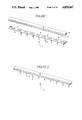
- This invention relates to the upholstered furniture industry, more particularly, a metal tack strip coated with a strip of foam used by this industry to secure upholstering material to a wood frame.
- FIGS. 1 and 2 there is shown by element 1 of FIG. 1, a prior art metal tack strip having a metal substrate portion 2 and a plurality of protruding members 3.
- Upholstering furniture craftsmen use such a tack strip 1 to engage the upholstering cloth to a furniture frame, usually made of wood, by wrapping a terminal portion of upholstering cloth around tack strip 1 with protrusions 3 extending through the cloth and then driving protrusions 3 into the appropriate wood portion of the frame.
- Foam tape 4 is an adhesive strip composed of a foam tape 5, removable backing 6, and an adhesive (not shown) disposed therebetween. Backing 6 is removed and foam type 5 is then adhesively affixed to the uppermost surface of substrate 2, resulting in the assembled tack strip 7 shown in FIG. 2. Attached foam tape 5 has the propensity to protect the upholstering cloth from the top edges of substrate 2 especially when element 7 is being hammered into place on a furniture frame after first being wrapped in a terminal portion of upholstering cloth.
- the invention is a tack strip padding applicator, more particularly an apparatus for applying an adhesive padding to a tack strip.
- the invention is composed of the following elements: (a) a conveyor for conveying a substrip along an elongated path; (b) an arm disposed above the conveyor, pivotable about an axis, biased to a first position, disposed so that the arm comes in contact with the substrate as the substrate is being conveyed along the elongated path by the conveyor, and adapted to be moved from a first position to a second position, when brought in contact with the substrate; (c) a feeding device disposed over the conveyor, for feeding to the substrate along a first path, an adhesive strip for removing a removable backing from the adhesive strip along the second path; (d) a cut-off device having a movable part for cutting said adhesive strip, the movable part adapted to be moved from a first position above the substrate to a second position below the substrate and biased to a first position; (e) an activator connected to the
- FIG. 1 is a perspective view of a metal tack strip and a strip of padding material (foam tape, plus backing) to be applied to the uppermost surface of the metal tack strip.
- FIG. 2 is a perspective view of an assembled tack strip comprising a combination of the foam tape (backing removed) adhered to the metal tack strip of FIG. 1.
- FIG. 3 is a fragmented cross section of the tack strip of FIG. 2 wrapped around a terminal portion of upholstering cloth to form an assembly and the assembly affixed to a furniture wood frame.
- FIG. 4 is a perspective overall view of the invention.
- FIGS. 5, 6, and 7 are partial perspective views of the drive mechanism and conveyor of the invention.
- FIGS. 8 and 9 are partial perspective views of the details of the tape feeding and cut-off device of the invention.
- FIG. 10 is a front elevation view of a foam tape safety switch employed in the invention.
- FIG. 11 is a cross section of the safety switch in FIG. 9 along line 10--10.
- FIG. 12 is a schematic view of the electrical circuit employed in the invention, tack strip not engaged.
- FIG. 13 is a partial schematic view of the electrical circuit of FIG. 12, tack strip engaged.
- the finished (coated) tack strip i.e., the combination 7 shown in FIG. 2 is taken and around it wrapped a terminal edge portion 9 of upholstering cloth.
- This combination is then affixed usually by a rubber hammer to a wooden substrate 8, a frame used to build upholstering furniture, the foam 5 protecting the upholstering cloth 9 from the metal substrate 2.
- the object of the invention was to manufacture the combination of foam and metal substrate (as shown by element 7) by a machine and avoid the prior art hand assembly.
- FIG. 4 The machine to accomplish this end is shown as a preferred embodiment in FIG. 4. It is composed of frame 10 having a chute-like member 14 on one and a platform 24 on the other terminal portion. Below chute 14 is box 13 which is used to receive the finished product 7 as it is manufactured. Product 7 is manufactured along an assembly line that moves from right to left. Uncoated tack strips 2 are placed on conveyor 45 (see FIG. 6), which travels in slot 122. Tack strip 2 travels under roller 123, which is journaled in stand-up member 124, passes under feeding apparatus 20 and 126, where tape 5 is stripped of its backing 6, applied to tack strip 2 and then cut off by cut off device 15. The finished product 7 is then conveyed to conveyor 67, then stripped from conveyor 67 by remover 23 and deposited through chute 14 into box 13.
- Tape 4 in strip form is wound on reel 12, which is disposed on axle 11, and is positioned below table 24.
- Above safety switch 16 is idler roller 13, rotatably journaled on axle 125.
- Tape 4 is threaded through safety switch 16 and over idler roller 13 into a feeding device made up of two spaced apart members, 126 and 20.
- This feeding device also includes pivot arm handle 21 and stripping rollers 128-127.
- Foam tape 4 as it comes off of reel 12, comprises a strip of foam 5, an adhesive (not numbered) on one side of the foam and a backing strip 6 on top of the adhesive.
- the foam tape 4 comes round pulley 13, down element 126 and element 20, it does so in groove 155 in elements 126 and 20 over which there is disposed plate 170 in FIGS. 7, 8, and 9.
- Backing strip 6 is threaded over the lower-most terminal edge of element 20, then along the bottom of element 20 to stripping rollers 128 and 127, then down through guide tube 18 into receptacle 19, disposed below reel 12.
- FIG. 5, 6, and 7, which describes the drive mechanism for the invention.
- motor 27 Apart from knife 75, the moving parts of the invention are driven by motor 27, which is connected to a source of electrical power through line 38.
- Motor 27 drives axle 32 affixed to sprocket 33, which is threaded onto chain 34.
- Chain 34 is threaded over sprocket 35, which is affixed to clutch 36.
- Clutch 36 is attached to drive means 37 and axle 159, which drive rollers 22 and 17.
- drive means 37 drives axle 159.
- Axle 159 is affixed to the gear 157 and gear 157 is engaged with gear 158 and drives same.
- Gear 158 is engaged with gear 161, which drives stripping roller 128.
- Gear 161 is meshed with gear 162, which is affixed to drive stripping roller 127.
- Gear 157 is meshed with gear 22 which is affixed to feed roller 17 and thus drives same.
- Pulley 13 has a groove 156 in its outer peripheral surface and elements 126 and 20 have a slot 155 therein in which tape 4 travels. In element 20, slot 155 is covered by cover means 80.
- Clutch 36 is a prior art device known as a wrap spring clutch made by the Warner Electric Braking Clutch Company, 449 Garden Street, South Beloit, Ill., 61080, under the lot number of SA500-H1-CCW-115 V.
- the clutch is activated by the activation of clutch solenoid 102 shown in FIGS. 12 and 13.
- Sprocket 64 is threaded onto chain 65 which is threaded over sprocket 68.
- Sprocket 68 drives pulley member 66.
- Conveyor 67 (an endless belt) is threaded over terminal pulley member 66 and another terminal pulley (not shown) spaced down stream therefrom.
- Power on motor 27 is on all the time, except when it is shut down for emergency reasons through safety or master switches that will be later explained.
- clutch solenoid 102 (FIG. 11) is activated power is provided to feed rollers 17 as well as stripping rollers 127 and 128.
- FIGS. 8 and 9 the tack strip is shown as moving from left to right. In FIG. 4, the flow is from right to left. It will be appreciated that the views presented by FIGS. 8 and 9 are from the direction reverse from as that shown in FIG. 4. Consequently, tack strip is shown as moving from left to right in FIGS. 8 and 9 which is correct, but if viewed from the opposite side, they would be moving from right to left as shown in FIG. 4.
- Table member 24 has in it slot 122, as previously explained, into which chain conveyor 45 is disposed.
- the protruding members 3 of tack strip 2 protrude through the open spaces in chain 45, thus enhancing its conveyance.
- Feeding device 20 is composed of a body in which there is a channel (not shown) in which tape 4 travels. Disposed over this channel is covered 80. Tape 4 travels down the channel and exits at the lower terminal edge of feeding device 20.
- Backing 6 is threaded around the terminal edge of lower portion of feeding device 20, threaded through stripping rollers 127-128 and disposed of in a manner previously described. Tape 4, with the adhesive now exposed, is applied to the uppermost surface of tack strip 2 as shown.
- Feeding of tape 4 is controlled by the two drive rollers 17, actuated through clutch 36 in a manner yet to be described.
- tack strip 2 passes under switch housing 42, it raises switch arm 80 and 81.
- switch arms 80 and 81 are both affixed to axle 91 and pivot thereabout.
- clutch 36 is activated and thus activates the feed rollers 17 and the feeding of tape 4, in a manner yet to be described.
- Knife 75 is adapted to be heated by heating element 130, which is connected to heating device through lead 72 and goes from a first to a second and then from a second to a first position, as previously explained. It is attached to guiding block 70 as shown. Element 69 is stationary and is not attached to guiding block 70. Guiding block 70 is affixed to plunger 73.
- Spring 71 by means of fastening means 78 and 79, is attached to element 59 and guiding block 70 respectively.
- knife 75 and its guiding block 70 plus plunger 73 are biased to the first position as shown in FIG. 7.
- solenoid 74 is activated through electrical lead 76 (in a manner hereinafter explained)
- plunger 73 is withdrawn from that normal position shown in FIG. 7, to that position shown in FIG. 8.
- spring 71 causes a plunger 73 and guide block 70 to retract to that position shown in FIG. 8.
- safety switch 16 is composed of back plate 82 with a channel 63 in it. Disposed in channel 63 is elongated member 84 which contains slot 181 and is affixed to back plate 82 by means of screws 89 disposed in slots 181.
- elongated element 84 can move upward and downward in a manner delimited by the length of slot 181.
- Elongated member 84 has two protrusions thereon, namely, protrusions 87 and 88, both of which are adapted to detect and engage any discontinuity or imperfections in backing 6 as tape 4 travels upwardly through element 16.
- tape 4 is oriented so that its underside is directly facing protrusions 87 and 88 on elongated member 84.
- switch 85 Disposed above slots 88 is switch 85 which includes plunger 86.
- plunger 86 When a discontinuity appears in backing 6, either protrusion 87 or 88 engages it and elongated member 84 is thus conveyed from the position shown in FIG. 10 to a position that engages plunger 86 and depresses same (not shown).
- plunger 86 of switch 85 is depressed, the entire apparatus is shut down. See switch 132 of FIGS. 12 and 13.
- Disposed over tape 4 and channel 63 is a plexiglass cover 83 so that the tape may be protected and viewed while it is traveling. Cover 83 also confines tape 4 to channel 63 during its travel through safety switch 16.
- Another switch 90 is disposed on plexiglass plate 83 so that if plate 83 is not in its closed position, switch 90 is adapted to keep power from going to motor 27.
- FIG. 12 and 13 the combination of arms 80-81 and the electrical circuit of the invention is shown. It will be noted that when arms 80-81 are pivoted about axle 91, they go from a first to a second position. Arms 80-81 are biased to the first position (FIG. 12) and are moved to their second position (FIG. 13) when the tack strip moves thereunder. When arms 80-81 are in their second position (tack strip under arms 80-81), plunger 92 is depressed, depressing plunger 93 of microswitch 94. Microswitch 94 has two sets of contacts, 95 and 96. Contacts 95 are normally closed and contacts 96 are normally opened.
- Sequence solenoid 101 is connected to lead 103 by lead 105 and to ground by lead 131.
- Sequence solenoid 101 is composed of a conventional solenoid with movable plunger 99.
- Plunger 99 is composed of a head 125 and a smaller shank 126.
- Spring 110 is disposed on shank 126 and engages head portion 125 and base 133.
- Master switch 127 is connected to by lead 111 to feed switch 112, which is connected by lead 113 to transformer 106.
- Transformer 106 is connected to relay for track switch to run feed 128, which is connected by leads 115 and 116 to track switch 117.
- Relay 128 is connected by lead 118 to a feed break motor 27.
- Master switch 127 is further connected through lead 114 to a hot knife variable control device 115. Through lead 72, the hot knife variable control 115 is connected to the hot knife heater 130.
- switch 80-81 When tack strip 2 engages the underside of arm switch 80-81, it causes arm switch 80-81 to move upward about pivot about axle 91. This causes movement of plunger 92 to move downward and depress plunger 93 of switch 94.
- switch 94 in its normal state has two sets of contacts, 95 and 96, normally closed and normally opened, respectively. Contact 96, the normally opened contact, is caused to go from its normally opened to a closed state when plunger 93 is depressed.
- the normally opened contacts 96 of microswitch 94 are closed, power is then placed on line 103 to cause clutch solenoid 101 to energize, thus causing this clutch to engage the axle 159 and thus drive gears 157, 158, 161, 162 and feed rollers 17.
- Sequence solenoid 101 is also energizing causing plunger 99 to be depressed against biasing spring 100. This causes plunger 27 of microswitch 98 to be fully extended. Microswitch 98 has one set of contacts 97, which are normally opened. When plunger 180 of microswitch 98 is fully extended, its contacts are closed, causing a path from/through it, over lead 76 through solenoid 74 (an actuator). Stated alternatively, plunger 99 fully extended causes the normally opened contacts 97 of microswitch 98 to become closed, thus providing an electrical path through it to the actuator. The actuator is the hot knife solenoid 74. No current yet flows through the now closed contacts 97 of microswitch 98.
Landscapes
- Engineering & Computer Science (AREA)
- Mechanical Engineering (AREA)
- General Engineering & Computer Science (AREA)
- Textile Engineering (AREA)
- Folding Of Thin Sheet-Like Materials, Special Discharging Devices, And Others (AREA)
Abstract
Description
Claims (24)
Priority Applications (1)
| Application Number | Priority Date | Filing Date | Title |
|---|---|---|---|
| US07/213,627 US4853067A (en) | 1988-06-30 | 1988-06-30 | Tack strip padding applicator |
Applications Claiming Priority (1)
| Application Number | Priority Date | Filing Date | Title |
|---|---|---|---|
| US07/213,627 US4853067A (en) | 1988-06-30 | 1988-06-30 | Tack strip padding applicator |
Publications (1)
| Publication Number | Publication Date |
|---|---|
| US4853067A true US4853067A (en) | 1989-08-01 |
Family
ID=22795836
Family Applications (1)
| Application Number | Title | Priority Date | Filing Date |
|---|---|---|---|
| US07/213,627 Expired - Fee Related US4853067A (en) | 1988-06-30 | 1988-06-30 | Tack strip padding applicator |
Country Status (1)
| Country | Link |
|---|---|
| US (1) | US4853067A (en) |
Cited By (4)
| Publication number | Priority date | Publication date | Assignee | Title |
|---|---|---|---|---|
| GB2298692A (en) * | 1995-03-08 | 1996-09-11 | Handy Button Mach | Securing protective sleeves to tack strips for upholstered furniture |
| US20040177490A1 (en) * | 2002-06-27 | 2004-09-16 | Haygood David L. | Upholstery fabric tack strips and methods of making same |
| US20140047671A1 (en) * | 2012-08-16 | 2014-02-20 | Glen P. Greathouse | Tackless Carpet Strip |
| US20210396014A1 (en) * | 2020-06-19 | 2021-12-23 | Douglas M. Stacye | Downspout sound treatment system and method |
Citations (5)
| Publication number | Priority date | Publication date | Assignee | Title |
|---|---|---|---|---|
| US2248744A (en) * | 1938-03-30 | 1941-07-08 | S & S Corrugated Paper Mach | Taping machine |
| US2574181A (en) * | 1948-03-13 | 1951-11-06 | S & S Corrugated Paper Mach | Target operated taping machine |
| US2721670A (en) * | 1952-01-11 | 1955-10-25 | Clifford D Keely | Box blank taping machine |
| US3564901A (en) * | 1968-09-25 | 1971-02-23 | George H Megrue | System and technique for gas analysis |
| US3892618A (en) * | 1973-06-21 | 1975-07-01 | Martin Griebat | Taping machine |
-
1988
- 1988-06-30 US US07/213,627 patent/US4853067A/en not_active Expired - Fee Related
Patent Citations (5)
| Publication number | Priority date | Publication date | Assignee | Title |
|---|---|---|---|---|
| US2248744A (en) * | 1938-03-30 | 1941-07-08 | S & S Corrugated Paper Mach | Taping machine |
| US2574181A (en) * | 1948-03-13 | 1951-11-06 | S & S Corrugated Paper Mach | Target operated taping machine |
| US2721670A (en) * | 1952-01-11 | 1955-10-25 | Clifford D Keely | Box blank taping machine |
| US3564901A (en) * | 1968-09-25 | 1971-02-23 | George H Megrue | System and technique for gas analysis |
| US3892618A (en) * | 1973-06-21 | 1975-07-01 | Martin Griebat | Taping machine |
Cited By (11)
| Publication number | Priority date | Publication date | Assignee | Title |
|---|---|---|---|---|
| GB2298692A (en) * | 1995-03-08 | 1996-09-11 | Handy Button Mach | Securing protective sleeves to tack strips for upholstered furniture |
| US5613817A (en) * | 1995-03-08 | 1997-03-25 | Handy Button Machine Company | Plastic tack strip with interlock |
| US20040177490A1 (en) * | 2002-06-27 | 2004-09-16 | Haygood David L. | Upholstery fabric tack strips and methods of making same |
| US7200916B2 (en) * | 2002-06-27 | 2007-04-10 | Haygood David L | Methods of making upholstery fabric tack strips |
| US20070107192A1 (en) * | 2002-06-27 | 2007-05-17 | Haygood David L | Upholstery fabric tack strips and methods of making same |
| US7828664B2 (en) | 2002-06-27 | 2010-11-09 | Haygood David L | Upholstery fabric tack strips and methods of making same |
| US20140047671A1 (en) * | 2012-08-16 | 2014-02-20 | Glen P. Greathouse | Tackless Carpet Strip |
| US8763203B2 (en) * | 2012-08-16 | 2014-07-01 | Glen P. Greathouse | Tackless carpet strip |
| US20150230646A1 (en) * | 2012-08-16 | 2015-08-20 | Glen P. Greathouse | Tackless carpet strip |
| US20210396014A1 (en) * | 2020-06-19 | 2021-12-23 | Douglas M. Stacye | Downspout sound treatment system and method |
| US11788294B2 (en) * | 2020-06-19 | 2023-10-17 | Douglas M. Stacye | Downspout sound treatment system and method |
Similar Documents
| Publication | Publication Date | Title |
|---|---|---|
| US4537005A (en) | Bag tying machine | |
| US7395927B2 (en) | Pocket tape with alternating adhesive and non-adhesive zones and overlying carrier tape | |
| CA1100027A (en) | Automatic high-speed wrapping machine | |
| CA1155806A (en) | Labelling equipment | |
| US4516735A (en) | Method and apparatus for winding webs | |
| US3856604A (en) | Machine for selectively cutting and gluing address labels | |
| US3985603A (en) | Method and apparatus for transportation of a label | |
| JPH0446810B2 (en) | ||
| US4243465A (en) | Apparatus for joining pieces of laminar material and in particular plywood core strips | |
| CA1259587A (en) | Bag tying machine | |
| US5417383A (en) | Treating and dispensing system for cutting tape | |
| CA1310846C (en) | Process and device for application of a carrying grip during the automatic sealing cartons | |
| US7837815B2 (en) | Adhesive segment indexing method and apparatus and roll of adhesive segments for use therewith | |
| EP0163127B1 (en) | A method and apparatus for forming pads of sheet items | |
| US4853067A (en) | Tack strip padding applicator | |
| US3446690A (en) | Apparatus for applying pressure-sensitive labels to cylindrical articles | |
| US3935057A (en) | Apparatus for securing the free end of a roll of fibrous web material | |
| US4828108A (en) | Package having fiber-containing sheath and apparatus and method for packaging | |
| US4052240A (en) | Taping device and method of taping | |
| US5159798A (en) | Method and apparatus for taping closed the open edge of an assembled newspaper having loose contents | |
| US5635017A (en) | Apparatus for applying closure tabs | |
| US4447281A (en) | Dispenser for applying adhesive tape | |
| JPH08230844A (en) | Sticking device of tape on thin film | |
| US4828109A (en) | Package having fiber-containing sheath and apparatus and method for packaging | |
| US5062251A (en) | Process and device for application of a carrying grip during the automatic sealing of cartons |
Legal Events
| Date | Code | Title | Description |
|---|---|---|---|
| AS | Assignment |
Owner name: ANTEG, INC., BOX 400, ROUTE 13, HICKORY, N.C., 286 Free format text: ASSIGNMENT OF ASSIGNORS INTEREST.;ASSIGNORS:ANNAS, DULIN L. SR.;TEAGUE, RICHARD M.;REEL/FRAME:004907/0049 Effective date: 19880620 Owner name: ANTEG, INC.,NORTH CAROLINA Free format text: ASSIGNMENT OF ASSIGNORS INTEREST;ASSIGNORS:ANNAS, DULIN L. SR.;TEAGUE, RICHARD M.;REEL/FRAME:004907/0049 Effective date: 19880620 |
|
| AS | Assignment |
Owner name: TSA, INC., BOX 675, ROUTE 10, HICKORY, N.C., 28601 Free format text: ASSIGNMENT OF ASSIGNORS INTEREST.;ASSIGNOR:ANTEG, INC.;REEL/FRAME:004990/0009 Effective date: 19881129 |
|
| AS | Assignment |
Owner name: TEAGUE, RICHARD M., NORTH CAROLINA Free format text: ASSIGNMENT OF ASSIGNORS INTEREST.;ASSIGNOR:TSA, INCORPORATED, A NC CORP.;REEL/FRAME:006236/0396 Effective date: 19920731 Owner name: ANNAS, DULIN L., NORTH CAROLINA Free format text: ASSIGNMENT OF ASSIGNORS INTEREST.;ASSIGNOR:TSA, INCORPORATED, A NC CORP.;REEL/FRAME:006236/0396 Effective date: 19920731 |
|
| REMI | Maintenance fee reminder mailed | ||
| LAPS | Lapse for failure to pay maintenance fees | ||
| FP | Lapsed due to failure to pay maintenance fee |
Effective date: 19930801 |
|
| STCH | Information on status: patent discontinuation |
Free format text: PATENT EXPIRED DUE TO NONPAYMENT OF MAINTENANCE FEES UNDER 37 CFR 1.362 |