US4852681A - Device for preventing the theft of motor vehicles - Google Patents
Device for preventing the theft of motor vehicles Download PDFInfo
- Publication number
- US4852681A US4852681A US07/215,601 US21560188A US4852681A US 4852681 A US4852681 A US 4852681A US 21560188 A US21560188 A US 21560188A US 4852681 A US4852681 A US 4852681A
- Authority
- US
- United States
- Prior art keywords
- relay
- theft
- transistor
- contact
- central unit
- Prior art date
- Legal status (The legal status is an assumption and is not a legal conclusion. Google has not performed a legal analysis and makes no representation as to the accuracy of the status listed.)
- Expired - Fee Related
Links
Images
Classifications
-
- B—PERFORMING OPERATIONS; TRANSPORTING
- B60—VEHICLES IN GENERAL
- B60R—VEHICLES, VEHICLE FITTINGS, OR VEHICLE PARTS, NOT OTHERWISE PROVIDED FOR
- B60R25/00—Fittings or systems for preventing or indicating unauthorised use or theft of vehicles
- B60R25/01—Fittings or systems for preventing or indicating unauthorised use or theft of vehicles operating on vehicle systems or fittings, e.g. on doors, seats or windscreens
- B60R25/04—Fittings or systems for preventing or indicating unauthorised use or theft of vehicles operating on vehicle systems or fittings, e.g. on doors, seats or windscreens operating on the propulsion system, e.g. engine or drive motor
- B60R25/045—Fittings or systems for preventing or indicating unauthorised use or theft of vehicles operating on vehicle systems or fittings, e.g. on doors, seats or windscreens operating on the propulsion system, e.g. engine or drive motor by limiting or cutting the electrical supply to the propulsion unit
Definitions
- the invention relates to an anti-theft device for motor vehicles which operates by cutting off the supply to the ignition.
- the relay is supplied only while the anti-theft device is in the monitoring mode, the circuit then being cut to the supply to the coil. On the other hand, while the vehicle is moving, the relay has to remain constantly live which offers risk should the coil of the relay or its supply wire become faulty. In a second case of anti-theft device, the relay is not supplied with current while the vehicle is moving and so this risk is eliminated. On the other hand, when the alarm is set, the relay is live and therefore consumption is considerable.
- the present invention sets out to alleviate these disadvantages of the prior art anti-theft devices, by offering a new anti-theft device in which the supply cut-out relay is not permanently supplied but is supplied only on condition that the anti-theft device is in the monitoring mode, the engine of the vehicle is stopped and an attempt at theft has materialised by closure of the "on" contact of the cut-out switch of the anti-theft steering.
- an anti-theft device for motor vehicles which operates by cutting out the supply to the ignition by means of a relay supplied from a central electronic unit of which the contact is in series with the "on" contact of the vehicle's anti-theft device which operates on the steering, characterised in that the relay is supplied by central unit through at least one transistor, the relay being connected to earth by a switch device maintained open while the engine is running.
- the trsansistor is earthed or grounded through the switch device.
- the relay is supplied by the central unit through two transistors mounted in a cascade arrangement.
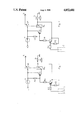
- FIG. 1 is a circuit diagram of an anti-theft device according to one embodiment of the invention, the central unit being in the monitoring mode, and
- FIG. 2 is similar to FIG. 1, the central unit being switched off while the vehicle is running.
- the anti-theft device described comprises a relay R L supplied by a central electronic control unit C and of which the contact S R is in series with the "on" contact M of the vehicle's cut-out switch anti-theft steering device.
- the output S of the contact S R supplies the ignition coil or an ignition computer (neither of which is shown).
- the relay R L is supplied by the central unit C through a transistor T 1 and is connected to earth by a contacting device D maintained open (FIG. 2) while the engine is running.
- This contactor device D may for example be the oil pressure contact which exists on the vehicle.
- the transistor T 1 is associated with a transistor T 2 mounted in cascade, in order to limit current intensities, with resistiors R 1 , R 2 , R 3 , R 4 . Furthermore, the collector of the transistor T 1 is connected directly to the contacting device D so that the transistor T 1 is not conductive when this contact D is open.
- the central unit C positively polarises the base of the transistor T 1 which then becomes conductive, which negatively polarises the base of the transistor T 2 which is therefore also in conductive state but does not supply the relay R L , because the contact M of the anti-theft device is broken (see FIG. 1).
- the relay R L is immediately supplied through the transistor T 2 which breaks the contact S R so that the supply to the coil or the ignition computer will prevent the vehicle being started.
Landscapes
- Engineering & Computer Science (AREA)
- Mechanical Engineering (AREA)
- Burglar Alarm Systems (AREA)
- Ignition Installations For Internal Combustion Engines (AREA)
- Lock And Its Accessories (AREA)
- Output Control And Ontrol Of Special Type Engine (AREA)
Abstract
Description
Claims (3)
Applications Claiming Priority (2)
| Application Number | Priority Date | Filing Date | Title |
|---|---|---|---|
| FR8709722 | 1987-07-09 | ||
| FR8709722A FR2617779B1 (en) | 1987-07-09 | 1987-07-09 | ANTI-THEFT DEVICE FOR MOTOR VEHICLES BY IGNITION SUPPLY CUT-OFF |
Publications (1)
| Publication Number | Publication Date |
|---|---|
| US4852681A true US4852681A (en) | 1989-08-01 |
Family
ID=9353012
Family Applications (1)
| Application Number | Title | Priority Date | Filing Date |
|---|---|---|---|
| US07/215,601 Expired - Fee Related US4852681A (en) | 1987-07-09 | 1988-07-06 | Device for preventing the theft of motor vehicles |
Country Status (6)
| Country | Link |
|---|---|
| US (1) | US4852681A (en) |
| EP (1) | EP0299849B1 (en) |
| JP (1) | JPS6430858A (en) |
| DE (1) | DE3874442T2 (en) |
| ES (1) | ES2034315T3 (en) |
| FR (1) | FR2617779B1 (en) |
Cited By (4)
| Publication number | Priority date | Publication date | Assignee | Title |
|---|---|---|---|---|
| US4955453A (en) * | 1988-10-06 | 1990-09-11 | Isuzu Motors Limited | Prevention against car burglar |
| GB2265679A (en) * | 1992-04-02 | 1993-10-06 | Neil Robert Green | Vehicle immobilisation apparatus |
| US5621252A (en) * | 1994-05-09 | 1997-04-15 | Bucknam; Steven H. | Apparatus for preventing unauthorized use of machinery |
| CN102602366A (en) * | 2012-03-23 | 2012-07-25 | 成都玺汇科技有限公司 | Vehicle immobilizer for preventing vehicle theft |
Families Citing this family (2)
| Publication number | Priority date | Publication date | Assignee | Title |
|---|---|---|---|---|
| DE4325617C2 (en) * | 1993-07-30 | 2003-07-03 | Siemens Ag | Device for ensuring the deactivation of an immobilizer in a motor vehicle |
| DE10006300C2 (en) * | 2000-02-12 | 2002-01-10 | Heiko Martens | Immobilizer for a vehicle powered by an internal combustion engine |
Citations (6)
| Publication number | Priority date | Publication date | Assignee | Title |
|---|---|---|---|---|
| US4485887A (en) * | 1983-10-31 | 1984-12-04 | Morano Michael W | Vehicular anti-theft device |
| US4533016A (en) * | 1983-10-14 | 1985-08-06 | Phantom Systems, Inc. | Antitheft ignition system and solenoid apparatus for use therewith |
| US4672225A (en) * | 1986-01-09 | 1987-06-09 | Hanisko John C P | Automotive anti-theft device |
| US4682062A (en) * | 1985-02-27 | 1987-07-21 | Zvi Weinberger | Anti-theft system for motor vehicles |
| US4733638A (en) * | 1986-08-14 | 1988-03-29 | Anderson Lyle V | Automotive anti-theft starting system |
| FR2608112A1 (en) * | 1986-12-12 | 1988-06-17 | Neiman Sa | Anti-theft ignition cut-out device for motor vehicles |
Family Cites Families (1)
| Publication number | Priority date | Publication date | Assignee | Title |
|---|---|---|---|---|
| US4119171A (en) * | 1975-02-24 | 1978-10-10 | Societe d'Exploitation des Brevets Neiman SA. | Safety anti-theft device for vehicles having a diesel engine |
-
1987
- 1987-07-09 FR FR8709722A patent/FR2617779B1/en not_active Expired - Lifetime
-
1988
- 1988-07-05 JP JP16607488A patent/JPS6430858A/en active Pending
- 1988-07-06 DE DE8888401760T patent/DE3874442T2/en not_active Expired - Fee Related
- 1988-07-06 US US07/215,601 patent/US4852681A/en not_active Expired - Fee Related
- 1988-07-06 ES ES198888401760T patent/ES2034315T3/en not_active Expired - Lifetime
- 1988-07-06 EP EP88401760A patent/EP0299849B1/en not_active Expired - Lifetime
Patent Citations (6)
| Publication number | Priority date | Publication date | Assignee | Title |
|---|---|---|---|---|
| US4533016A (en) * | 1983-10-14 | 1985-08-06 | Phantom Systems, Inc. | Antitheft ignition system and solenoid apparatus for use therewith |
| US4485887A (en) * | 1983-10-31 | 1984-12-04 | Morano Michael W | Vehicular anti-theft device |
| US4682062A (en) * | 1985-02-27 | 1987-07-21 | Zvi Weinberger | Anti-theft system for motor vehicles |
| US4672225A (en) * | 1986-01-09 | 1987-06-09 | Hanisko John C P | Automotive anti-theft device |
| US4733638A (en) * | 1986-08-14 | 1988-03-29 | Anderson Lyle V | Automotive anti-theft starting system |
| FR2608112A1 (en) * | 1986-12-12 | 1988-06-17 | Neiman Sa | Anti-theft ignition cut-out device for motor vehicles |
Cited By (4)
| Publication number | Priority date | Publication date | Assignee | Title |
|---|---|---|---|---|
| US4955453A (en) * | 1988-10-06 | 1990-09-11 | Isuzu Motors Limited | Prevention against car burglar |
| GB2265679A (en) * | 1992-04-02 | 1993-10-06 | Neil Robert Green | Vehicle immobilisation apparatus |
| US5621252A (en) * | 1994-05-09 | 1997-04-15 | Bucknam; Steven H. | Apparatus for preventing unauthorized use of machinery |
| CN102602366A (en) * | 2012-03-23 | 2012-07-25 | 成都玺汇科技有限公司 | Vehicle immobilizer for preventing vehicle theft |
Also Published As
| Publication number | Publication date |
|---|---|
| ES2034315T3 (en) | 1993-04-01 |
| DE3874442T2 (en) | 1993-01-28 |
| FR2617779A1 (en) | 1989-01-13 |
| FR2617779B1 (en) | 1990-07-20 |
| DE3874442D1 (en) | 1992-10-15 |
| JPS6430858A (en) | 1989-02-01 |
| EP0299849A1 (en) | 1989-01-18 |
| EP0299849B1 (en) | 1992-09-09 |
Similar Documents
| Publication | Publication Date | Title |
|---|---|---|
| US5191228A (en) | Vehicle battery disconnect antitheft device | |
| US4485887A (en) | Vehicular anti-theft device | |
| US3956732A (en) | Automobile theft alarm with ignition controlled automatic arming means | |
| US4342024A (en) | Vehicle burglar alarm apparatus with electronic memory and digital disabling combination | |
| US4449605A (en) | Device for preventing theft of motor vehicles | |
| US4636651A (en) | Vehicle anti-theft system with pressure sensitive sensor | |
| US4992670A (en) | Ignition disabling anti-theft device | |
| US6445282B1 (en) | Theft prevention system for motor vehicles | |
| US4278963A (en) | Automotive anti-theft system | |
| US4107543A (en) | Vehicle antitheft system | |
| US4852681A (en) | Device for preventing the theft of motor vehicles | |
| US2935730A (en) | Vehicle alarm system | |
| US3885164A (en) | Anti-theft system for automotive vehicles | |
| US3614458A (en) | Automobile theft prevention device | |
| US4892167A (en) | Automatic electronic and mechanical system to avoid vehicle theft | |
| US3525414A (en) | Protective automotive ignition circuit | |
| US5477090A (en) | Auto anti-theft device | |
| US4371052A (en) | Anti-theft device for motor vehicles | |
| US4709777A (en) | Vehicle power door locks, ignition key interlock system therefor | |
| US4549090A (en) | Device for preventing theft of motor vehicles | |
| JPS6140577B2 (en) | ||
| US4857888A (en) | Automotive alarm | |
| US3628056A (en) | Antitheft starting and ignition system | |
| KR100229462B1 (en) | A burglarproof device of an automobile | |
| GB2319653A (en) | Security Battery |
Legal Events
| Date | Code | Title | Description |
|---|---|---|---|
| AS | Assignment |
Owner name: NEIMAN, 39 AVENUE MARCEAU, 92400 COURBEVOIE, FRANC Free format text: ASSIGNMENT OF ASSIGNORS INTEREST.;ASSIGNOR:BOMBLED, JEAN;REEL/FRAME:004937/0969 Effective date: 19880630 |
|
| FEPP | Fee payment procedure |
Free format text: PAYOR NUMBER ASSIGNED (ORIGINAL EVENT CODE: ASPN); ENTITY STATUS OF PATENT OWNER: LARGE ENTITY |
|
| FPAY | Fee payment |
Year of fee payment: 4 |
|
| FPAY | Fee payment |
Year of fee payment: 8 |
|
| REMI | Maintenance fee reminder mailed | ||
| LAPS | Lapse for failure to pay maintenance fees | ||
| FP | Lapsed due to failure to pay maintenance fee |
Effective date: 20010801 |
|
| STCH | Information on status: patent discontinuation |
Free format text: PATENT EXPIRED DUE TO NONPAYMENT OF MAINTENANCE FEES UNDER 37 CFR 1.362 |