US4848553A - Friction laminate and disk assembly - Google Patents
Friction laminate and disk assembly Download PDFInfo
- Publication number
- US4848553A US4848553A US07/174,670 US17467088A US4848553A US 4848553 A US4848553 A US 4848553A US 17467088 A US17467088 A US 17467088A US 4848553 A US4848553 A US 4848553A
- Authority
- US
- United States
- Prior art keywords
- friction
- backing plate
- laminate
- opening
- segment
- Prior art date
- Legal status (The legal status is an assumption and is not a legal conclusion. Google has not performed a legal analysis and makes no representation as to the accuracy of the status listed.)
- Expired - Fee Related
Links
Images
Classifications
-
- F—MECHANICAL ENGINEERING; LIGHTING; HEATING; WEAPONS; BLASTING
- F04—POSITIVE - DISPLACEMENT MACHINES FOR LIQUIDS; PUMPS FOR LIQUIDS OR ELASTIC FLUIDS
- F04B—POSITIVE-DISPLACEMENT MACHINES FOR LIQUIDS; PUMPS
- F04B39/00—Component parts, details, or accessories, of pumps or pumping systems specially adapted for elastic fluids, not otherwise provided for in, or of interest apart from, groups F04B25/00 - F04B37/00
-
- F—MECHANICAL ENGINEERING; LIGHTING; HEATING; WEAPONS; BLASTING
- F16—ENGINEERING ELEMENTS AND UNITS; GENERAL MEASURES FOR PRODUCING AND MAINTAINING EFFECTIVE FUNCTIONING OF MACHINES OR INSTALLATIONS; THERMAL INSULATION IN GENERAL
- F16D—COUPLINGS FOR TRANSMITTING ROTATION; CLUTCHES; BRAKES
- F16D13/00—Friction clutches
- F16D13/58—Details
- F16D13/60—Clutching elements
- F16D13/64—Clutch-plates; Clutch-lamellae
-
- F—MECHANICAL ENGINEERING; LIGHTING; HEATING; WEAPONS; BLASTING
- F16—ENGINEERING ELEMENTS AND UNITS; GENERAL MEASURES FOR PRODUCING AND MAINTAINING EFFECTIVE FUNCTIONING OF MACHINES OR INSTALLATIONS; THERMAL INSULATION IN GENERAL
- F16D—COUPLINGS FOR TRANSMITTING ROTATION; CLUTCHES; BRAKES
- F16D13/00—Friction clutches
- F16D13/22—Friction clutches with axially-movable clutching members
Definitions
- This invention relates generally to the design of friction elements utilized in driven disks of dry friction clutches. More particularly, the invention relates to the arrangement and structural characteristics of friction elements adapted for installation in such disks.
- the friction laminate and disk assembly of this invention includes a plurality of friction laminate members each disposed rigidly over one of a plurality of support segment openings in the assembly.
- Each laminate comprises a single backing plate having a pair of opposed sides, wherein one of a pair of friction pads is each bonded to one of the opposed sides of the single backing plate.
- the single backing plate includes an offset portion which extends into the opening of an associated support segment under an interference fit with at least a portion of the boundary of the opening.
- the laminate is capable of accommodating significant circumferential friction loads without undergoing relative movement with respect to the support segment. The latter measure significantly improves the load-carrying ability of the friction element over systems which rely entirely on shear load capacities of rivets employed to affix backing plates to support segments.
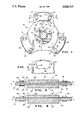
- FIG. 1 is a side view of a friction disk assembly which incorporates a preferred embodiment of the friction laminate of the present invention.
- FIG. 2 is a fragmentary view of a friction element support segment of the clutch driven disk of FIG. 1, shown without the friction laminate incorporated therein.
- FIG. 3 is a view along lines 3--3 of FIG. 1, showing a cross sectional view of a friction laminate affixed by rivets to a support segment.
- FIG. 4 is an alternate embodiment of the friction laminate of the present invention, as would also be viewed along lines 3--3 in lieu of the view shown in FIG. 3.
- a clutch driven disk 10 is shown apart from a friction clutch (not shown) in which it is designed to operate.
- the driven disk 10 includes three circumferentially spaced friction element support segments 12 which extend radially from central disk portion 14.
- the disk portion 14 is secured by a set of rivets 16 to a splined hub 18.
- the hub is designed for coupling to a splined engine propshaft (not shown).
- Each of the friction element support segments 12 contains a friction laminate or pad assembly 20, which includes a pair of opposed friction elements or pads 22.
- each friction pad 22 includes a radially extending friction surface 24, which is parallel to an identical counterpart surface 24 on the opposite pad 22.
- each laminate assembly 20 contains a pair of pads 22 secured on opposite sides of a singular backing plate 30, the latter of which is affixed by rivets 46 to one of the three support segments 12.
- Each of the rivets 46 will pass through an aperture 52 in one of the support segments 12 for securing a friction pad assembly 20 to a particular support segment 12.
- FIG. 3 one preferred embodiment is shown wherein the backing plate 30 contains an axially or transversely offset portion 34.
- the support segment 12 lies in a plane A--A as shown.
- the pads 22 will have equal thicknesses as shown.
- the boundary 42 of the axially offset portion 34 will preferably engage, under an interference fit, the edge or boundary 32, at least in part, of the support segment aperture 40. This will assure against any relative circumferential or transverse movement between the friction laminate or pad assembly 20 and the support segment 12. Otherwise, the rivets 46 would be forced to carry all of the circumferentially applied friction loads on the assemblies 20, and over a period time rivets tend to become elongated and permit looseness.
- a second preferred embodiment, shown in FIG. 4, does not have an axially offset portion 34 as does that of FIG. 3.
- the friction pad assembly 20' has an entirely flat backing plate which lies fully within a plane B'--B', parallel to a plane A'--A' passing through the center of the support segment 12'.
- axially extending tabs 36 are utilized to engage the radial boundaries 32' of aperture 40' to provide an interference fit between the backing plate and the support segment.
- This form of the invention operates in the same manner as the interference fit between the boundary 42 of the offset portion 34 and the boundary 32 of the aperture 40 in the version of FIG. 3.
- the lower pad 22' has a thickness which must be equal to the thickness of the upper pad plus the thickness of the support segment in order for the friction surfaces 24' to be, as is preferable, equidistant from the plane A'--A.
- the friction pad is a copper-base powered metal, of approximately eighty percent copper.
- the backing plate is preferably formed of a copper plated steel (having a plating thickness of 3 to 4 ten thousandths of an inch) to which the friction pads are sintered via the use of a copper-flux paste an adhesive bonding agent, at approximately 1700° F.
- the tolerance range between either the support segment opening boundary 32 and the associated offset boundary 42 or the tab 36 is approximately 1 to 3 thousands of an inch maximum. This will provide an interference fit necessary to assure rigid transverse securement.
Landscapes
- Engineering & Computer Science (AREA)
- General Engineering & Computer Science (AREA)
- Mechanical Engineering (AREA)
- Braking Arrangements (AREA)
- Mechanical Operated Clutches (AREA)
Abstract
Description
Claims (3)
Priority Applications (7)
| Application Number | Priority Date | Filing Date | Title |
|---|---|---|---|
| US07/174,670 US4848553A (en) | 1988-03-29 | 1988-03-29 | Friction laminate and disk assembly |
| ZA891893A ZA891893B (en) | 1988-03-29 | 1989-03-13 | Friction laminate and disk assembly |
| EP89302656A EP0335537A3 (en) | 1988-03-29 | 1989-03-17 | Friction laminate and disk assembly |
| BR898901360A BR8901360A (en) | 1988-03-29 | 1989-03-22 | ASSEMBLY OF FRICTION LAMINATE AND DISC |
| AU31761/89A AU605086B2 (en) | 1988-03-29 | 1989-03-28 | Friction laminate and disk assembly |
| KR1019890003922A KR890014891A (en) | 1988-03-29 | 1989-03-28 | Friction disc assembly |
| JP1075219A JPH01299335A (en) | 1988-03-29 | 1989-03-29 | Friction disk assembly |
Applications Claiming Priority (1)
| Application Number | Priority Date | Filing Date | Title |
|---|---|---|---|
| US07/174,670 US4848553A (en) | 1988-03-29 | 1988-03-29 | Friction laminate and disk assembly |
Publications (1)
| Publication Number | Publication Date |
|---|---|
| US4848553A true US4848553A (en) | 1989-07-18 |
Family
ID=22637057
Family Applications (1)
| Application Number | Title | Priority Date | Filing Date |
|---|---|---|---|
| US07/174,670 Expired - Fee Related US4848553A (en) | 1988-03-29 | 1988-03-29 | Friction laminate and disk assembly |
Country Status (7)
| Country | Link |
|---|---|
| US (1) | US4848553A (en) |
| EP (1) | EP0335537A3 (en) |
| JP (1) | JPH01299335A (en) |
| KR (1) | KR890014891A (en) |
| AU (1) | AU605086B2 (en) |
| BR (1) | BR8901360A (en) |
| ZA (1) | ZA891893B (en) |
Cited By (5)
| Publication number | Priority date | Publication date | Assignee | Title |
|---|---|---|---|---|
| US5135094A (en) * | 1990-06-22 | 1992-08-04 | Valeo | Friction disc, in particular for a clutch |
| US20060037819A1 (en) * | 2004-08-19 | 2006-02-23 | Shimano, Inc. | Bicycle disk brake rotor with laminated components having differing thicknesses |
| US20090152058A1 (en) * | 2006-09-11 | 2009-06-18 | Goodrich Corporation | Brake lining cup attachment method for reduced wear |
| US20170184164A1 (en) * | 2014-05-19 | 2017-06-29 | Tech M3, Inc | Brake Rotor With Working Surface Inserts |
| US20190368560A1 (en) * | 2013-03-15 | 2019-12-05 | Tech M3, Inc. | Wear resistant braking systems |
Citations (19)
| Publication number | Priority date | Publication date | Assignee | Title |
|---|---|---|---|---|
| US2033835A (en) * | 1931-10-07 | 1936-03-10 | Eclipse Aviat Corp | Driving mechanism |
| US3064782A (en) * | 1958-12-15 | 1962-11-20 | Bendix Corp | Lining button-spring loaded |
| US3194347A (en) * | 1962-09-27 | 1965-07-13 | Girling Ltd | Disc for disc brakes |
| US3412836A (en) * | 1967-03-06 | 1968-11-26 | Caterpillar Tractor Co | Friction disc of segmented elements |
| US3422936A (en) * | 1966-05-05 | 1969-01-21 | Hispano Suiza Lallemant Soc | Sector type friction brake disc |
| US3433334A (en) * | 1967-06-14 | 1969-03-18 | Lambert & Brake Corp | Disc brake and lining disc assembly |
| US3452844A (en) * | 1966-10-06 | 1969-07-01 | Hispano Suiza Lallemant Soc | Segmented brake disc |
| US3526307A (en) * | 1968-07-29 | 1970-09-01 | Borg Warner | Friction member |
| US3746139A (en) * | 1971-07-19 | 1973-07-17 | Goodrich Co B F | Friction disc member for brake or clutch |
| US3807534A (en) * | 1972-06-16 | 1974-04-30 | Bendix Corp | Friction disc |
| US3857469A (en) * | 1971-11-04 | 1974-12-31 | Dunlop Ltd | Improvements in composite articles |
| US3913716A (en) * | 1974-04-04 | 1975-10-21 | Abex Corp | Welded friction article and method of assembly |
| US3948364A (en) * | 1973-02-28 | 1976-04-06 | Friction Products Co. | Single mixture metallic brake or clutch plate |
| US3986588A (en) * | 1975-09-23 | 1976-10-19 | Warn Industries, Inc. | Brake-clutch assembly for a winch |
| US4013147A (en) * | 1975-09-02 | 1977-03-22 | The Bendix Corporation | Segmented friction disc for brakes |
| US4119179A (en) * | 1976-06-18 | 1978-10-10 | Messier-Hispano | Brake disc structure |
| US4173681A (en) * | 1977-07-25 | 1979-11-06 | Societe Abex Pagid Equipement S.A. | Brake pad with integral organic backplate |
| US4326614A (en) * | 1980-05-19 | 1982-04-27 | Matagrano Theodore T | Disc caliper clutch with easy access and burnout proof rotor |
| US4613021A (en) * | 1983-12-21 | 1986-09-23 | Societe Europeene De Propulsion | Brake disc with removable pads |
Family Cites Families (1)
| Publication number | Priority date | Publication date | Assignee | Title |
|---|---|---|---|---|
| GB880984A (en) * | 1958-07-25 | 1961-10-25 | Fichtel & Sachs Ag | Improvements in or relating to friction surfaces of disc clutches or brakes |
-
1988
- 1988-03-29 US US07/174,670 patent/US4848553A/en not_active Expired - Fee Related
-
1989
- 1989-03-13 ZA ZA891893A patent/ZA891893B/en unknown
- 1989-03-17 EP EP89302656A patent/EP0335537A3/en not_active Withdrawn
- 1989-03-22 BR BR898901360A patent/BR8901360A/en unknown
- 1989-03-28 AU AU31761/89A patent/AU605086B2/en not_active Expired - Fee Related
- 1989-03-28 KR KR1019890003922A patent/KR890014891A/en not_active Application Discontinuation
- 1989-03-29 JP JP1075219A patent/JPH01299335A/en active Pending
Patent Citations (19)
| Publication number | Priority date | Publication date | Assignee | Title |
|---|---|---|---|---|
| US2033835A (en) * | 1931-10-07 | 1936-03-10 | Eclipse Aviat Corp | Driving mechanism |
| US3064782A (en) * | 1958-12-15 | 1962-11-20 | Bendix Corp | Lining button-spring loaded |
| US3194347A (en) * | 1962-09-27 | 1965-07-13 | Girling Ltd | Disc for disc brakes |
| US3422936A (en) * | 1966-05-05 | 1969-01-21 | Hispano Suiza Lallemant Soc | Sector type friction brake disc |
| US3452844A (en) * | 1966-10-06 | 1969-07-01 | Hispano Suiza Lallemant Soc | Segmented brake disc |
| US3412836A (en) * | 1967-03-06 | 1968-11-26 | Caterpillar Tractor Co | Friction disc of segmented elements |
| US3433334A (en) * | 1967-06-14 | 1969-03-18 | Lambert & Brake Corp | Disc brake and lining disc assembly |
| US3526307A (en) * | 1968-07-29 | 1970-09-01 | Borg Warner | Friction member |
| US3746139A (en) * | 1971-07-19 | 1973-07-17 | Goodrich Co B F | Friction disc member for brake or clutch |
| US3857469A (en) * | 1971-11-04 | 1974-12-31 | Dunlop Ltd | Improvements in composite articles |
| US3807534A (en) * | 1972-06-16 | 1974-04-30 | Bendix Corp | Friction disc |
| US3948364A (en) * | 1973-02-28 | 1976-04-06 | Friction Products Co. | Single mixture metallic brake or clutch plate |
| US3913716A (en) * | 1974-04-04 | 1975-10-21 | Abex Corp | Welded friction article and method of assembly |
| US4013147A (en) * | 1975-09-02 | 1977-03-22 | The Bendix Corporation | Segmented friction disc for brakes |
| US3986588A (en) * | 1975-09-23 | 1976-10-19 | Warn Industries, Inc. | Brake-clutch assembly for a winch |
| US4119179A (en) * | 1976-06-18 | 1978-10-10 | Messier-Hispano | Brake disc structure |
| US4173681A (en) * | 1977-07-25 | 1979-11-06 | Societe Abex Pagid Equipement S.A. | Brake pad with integral organic backplate |
| US4326614A (en) * | 1980-05-19 | 1982-04-27 | Matagrano Theodore T | Disc caliper clutch with easy access and burnout proof rotor |
| US4613021A (en) * | 1983-12-21 | 1986-09-23 | Societe Europeene De Propulsion | Brake disc with removable pads |
Cited By (7)
| Publication number | Priority date | Publication date | Assignee | Title |
|---|---|---|---|---|
| US5135094A (en) * | 1990-06-22 | 1992-08-04 | Valeo | Friction disc, in particular for a clutch |
| US20060037819A1 (en) * | 2004-08-19 | 2006-02-23 | Shimano, Inc. | Bicycle disk brake rotor with laminated components having differing thicknesses |
| US20090152058A1 (en) * | 2006-09-11 | 2009-06-18 | Goodrich Corporation | Brake lining cup attachment method for reduced wear |
| US20190368560A1 (en) * | 2013-03-15 | 2019-12-05 | Tech M3, Inc. | Wear resistant braking systems |
| US10895295B2 (en) | 2013-03-15 | 2021-01-19 | Tech M3, Inc. | Wear resistant braking systems |
| US11624416B2 (en) | 2013-03-15 | 2023-04-11 | Tech M3, Inc. | Wear resistant braking systems |
| US20170184164A1 (en) * | 2014-05-19 | 2017-06-29 | Tech M3, Inc | Brake Rotor With Working Surface Inserts |
Also Published As
| Publication number | Publication date |
|---|---|
| ZA891893B (en) | 1989-11-29 |
| BR8901360A (en) | 1989-11-07 |
| AU605086B2 (en) | 1991-01-03 |
| AU3176189A (en) | 1989-10-05 |
| KR890014891A (en) | 1989-10-25 |
| JPH01299335A (en) | 1989-12-04 |
| EP0335537A2 (en) | 1989-10-04 |
| EP0335537A3 (en) | 1990-08-16 |
Similar Documents
| Publication | Publication Date | Title |
|---|---|---|
| US4646900A (en) | Friction material and carrier plate assembly | |
| US6106421A (en) | Uncoupled belt pulley | |
| US4741424A (en) | Clutch disc | |
| US5284232A (en) | Clutch with structural plates, especially of carbon-carbon | |
| EP0717211B1 (en) | Flexible plate for transmitting torque | |
| JPH05500409A (en) | Carbon composite laminated structure | |
| US4516672A (en) | Progressive engagement friction disc | |
| US4848553A (en) | Friction laminate and disk assembly | |
| US3550740A (en) | Segmented friction member for brake or clutch | |
| US4860872A (en) | Friction disc assembly | |
| US4869356A (en) | Clutch disk with spring cushioned friction element | |
| US2916123A (en) | Clutch element with ceramic-metallic friction disc | |
| US4669592A (en) | Torsional damper device | |
| US4762214A (en) | Clutch plate and method of making same | |
| US4445607A (en) | Clutch driven plate assembly | |
| US4607738A (en) | Friction clutch cover assemblies | |
| US4270640A (en) | Friction clutch driven plates | |
| JPH0214660Y2 (en) | ||
| US3964586A (en) | Clutch disc | |
| CA1140489A (en) | Friction disc | |
| EP0180389A2 (en) | Friction components for clutch plates and the like | |
| US2812842A (en) | Friction clutch plate | |
| US1927995A (en) | Plate clutch | |
| JP2604091B2 (en) | Pressure plate mounting structure for clutch cover assembly | |
| EP0223060A1 (en) | Damper disc assembly for friction clutches |
Legal Events
| Date | Code | Title | Description |
|---|---|---|---|
| AS | Assignment |
Owner name: DANA CORPORATION, TOLEDO, OHIO, A CORP. OF VIRGINI Free format text: ASSIGNMENT OF ASSIGNORS INTEREST.;ASSIGNOR:CAMERON, MICKEY G.;REEL/FRAME:004856/0652 Effective date: 19880325 Owner name: DANA CORPORATION, A CORP. OF VIRGINIA,OHIO Free format text: ASSIGNMENT OF ASSIGNORS INTEREST;ASSIGNOR:CAMERON, MICKEY G.;REEL/FRAME:004856/0652 Effective date: 19880325 |
|
| FPAY | Fee payment |
Year of fee payment: 4 |
|
| FEPP | Fee payment procedure |
Free format text: PAYOR NUMBER ASSIGNED (ORIGINAL EVENT CODE: ASPN); ENTITY STATUS OF PATENT OWNER: LARGE ENTITY |
|
| REMI | Maintenance fee reminder mailed | ||
| LAPS | Lapse for failure to pay maintenance fees | ||
| FP | Lapsed due to failure to pay maintenance fee |
Effective date: 19970723 |
|
| STCH | Information on status: patent discontinuation |
Free format text: PATENT EXPIRED DUE TO NONPAYMENT OF MAINTENANCE FEES UNDER 37 CFR 1.362 |