US4846420A - Magnetic tape loading method and apparatus - Google Patents
Magnetic tape loading method and apparatus Download PDFInfo
- Publication number
- US4846420A US4846420A US07/157,663 US15766388A US4846420A US 4846420 A US4846420 A US 4846420A US 15766388 A US15766388 A US 15766388A US 4846420 A US4846420 A US 4846420A
- Authority
- US
- United States
- Prior art keywords
- tape
- decompression
- winding
- magnetic
- magnetic tape
- Prior art date
- Legal status (The legal status is an assumption and is not a legal conclusion. Google has not performed a legal analysis and makes no representation as to the accuracy of the status listed.)
- Expired - Lifetime
Links
- 238000011068 loading method Methods 0.000 title claims abstract description 45
- 238000004804 winding Methods 0.000 claims abstract description 123
- 230000006837 decompression Effects 0.000 claims abstract description 85
- 230000001360 synchronised effect Effects 0.000 claims description 3
- 238000000034 method Methods 0.000 abstract description 22
- 230000009471 action Effects 0.000 description 9
- 230000008569 process Effects 0.000 description 9
- 238000004519 manufacturing process Methods 0.000 description 6
- 230000000704 physical effect Effects 0.000 description 5
- 239000003570 air Substances 0.000 description 3
- 230000000694 effects Effects 0.000 description 3
- 230000006866 deterioration Effects 0.000 description 2
- 238000010586 diagram Methods 0.000 description 2
- 235000012489 doughnuts Nutrition 0.000 description 2
- 239000004744 fabric Substances 0.000 description 2
- 239000000463 material Substances 0.000 description 2
- 230000007246 mechanism Effects 0.000 description 2
- 239000004952 Polyamide Substances 0.000 description 1
- 230000001133 acceleration Effects 0.000 description 1
- 230000002411 adverse Effects 0.000 description 1
- 239000012080 ambient air Substances 0.000 description 1
- 230000008859 change Effects 0.000 description 1
- 238000006243 chemical reaction Methods 0.000 description 1
- 239000000835 fiber Substances 0.000 description 1
- 230000004907 flux Effects 0.000 description 1
- 238000007689 inspection Methods 0.000 description 1
- 238000012423 maintenance Methods 0.000 description 1
- 238000012986 modification Methods 0.000 description 1
- 230000004048 modification Effects 0.000 description 1
- 229920002647 polyamide Polymers 0.000 description 1
- 230000008054 signal transmission Effects 0.000 description 1
- 230000005236 sound signal Effects 0.000 description 1
Images


Classifications
-
- B—PERFORMING OPERATIONS; TRANSPORTING
- B65—CONVEYING; PACKING; STORING; HANDLING THIN OR FILAMENTARY MATERIAL
- B65H—HANDLING THIN OR FILAMENTARY MATERIAL, e.g. SHEETS, WEBS, CABLES
- B65H18/00—Winding webs
- B65H18/08—Web-winding mechanisms
- B65H18/26—Mechanisms for controlling contact pressure on winding-web package, e.g. for regulating the quantity of air between web layers
-
- G—PHYSICS
- G11—INFORMATION STORAGE
- G11B—INFORMATION STORAGE BASED ON RELATIVE MOVEMENT BETWEEN RECORD CARRIER AND TRANSDUCER
- G11B15/00—Driving, starting or stopping record carriers of filamentary or web form; Driving both such record carriers and heads; Guiding such record carriers or containers therefor; Control thereof; Control of operating function
- G11B15/18—Driving; Starting; Stopping; Arrangements for control or regulation thereof
- G11B15/26—Driving record carriers by members acting directly or indirectly thereon
- G11B15/32—Driving record carriers by members acting directly or indirectly thereon through the reels or cores on to which the record carrier is wound
-
- G—PHYSICS
- G11—INFORMATION STORAGE
- G11B—INFORMATION STORAGE BASED ON RELATIVE MOVEMENT BETWEEN RECORD CARRIER AND TRANSDUCER
- G11B15/00—Driving, starting or stopping record carriers of filamentary or web form; Driving both such record carriers and heads; Guiding such record carriers or containers therefor; Control thereof; Control of operating function
- G11B15/60—Guiding record carrier
- G11B15/66—Threading; Loading; Automatic self-loading
-
- G—PHYSICS
- G11—INFORMATION STORAGE
- G11B—INFORMATION STORAGE BASED ON RELATIVE MOVEMENT BETWEEN RECORD CARRIER AND TRANSDUCER
- G11B23/00—Record carriers not specific to the method of recording or reproducing; Accessories, e.g. containers, specially adapted for co-operation with the recording or reproducing apparatus ; Intermediate mediums; Apparatus or processes specially adapted for their manufacture
- G11B23/02—Containers; Storing means both adapted to cooperate with the recording or reproducing means
- G11B23/113—Apparatus or processes specially adapted for the manufacture of magazines or cassettes, e.g. initial loading into container
-
- B—PERFORMING OPERATIONS; TRANSPORTING
- B65—CONVEYING; PACKING; STORING; HANDLING THIN OR FILAMENTARY MATERIAL
- B65H—HANDLING THIN OR FILAMENTARY MATERIAL, e.g. SHEETS, WEBS, CABLES
- B65H2301/00—Handling processes for sheets or webs
- B65H2301/40—Type of handling process
- B65H2301/41—Winding, unwinding
- B65H2301/413—Supporting web roll
- B65H2301/4136—Mounting arrangements not otherwise provided for
- B65H2301/41368—Mounting arrangements not otherwise provided for one or two lateral flanges covering part of or entire web diameter
-
- B—PERFORMING OPERATIONS; TRANSPORTING
- B65—CONVEYING; PACKING; STORING; HANDLING THIN OR FILAMENTARY MATERIAL
- B65H—HANDLING THIN OR FILAMENTARY MATERIAL, e.g. SHEETS, WEBS, CABLES
- B65H2801/00—Application field
- B65H2801/45—Audio or video tape players, or related mechanism
-
- Y—GENERAL TAGGING OF NEW TECHNOLOGICAL DEVELOPMENTS; GENERAL TAGGING OF CROSS-SECTIONAL TECHNOLOGIES SPANNING OVER SEVERAL SECTIONS OF THE IPC; TECHNICAL SUBJECTS COVERED BY FORMER USPC CROSS-REFERENCE ART COLLECTIONS [XRACs] AND DIGESTS
- Y10—TECHNICAL SUBJECTS COVERED BY FORMER USPC
- Y10S—TECHNICAL SUBJECTS COVERED BY FORMER USPC CROSS-REFERENCE ART COLLECTIONS [XRACs] AND DIGESTS
- Y10S242/00—Winding, tensioning, or guiding
- Y10S242/908—Fluid treatment or handling
Definitions
- the present invention relates to a magnetic tape loading method and apparatus for initially loading a magnetic tape of a predetermined length onto a tape winding body from a roll of "raw" magnetic tape of an article width, for rewinding a magnetic tape previously wound on a tape winding body to transfer the magnetic tape to another winding body, for loading a wide raw magnetic tape having a width larger than the article width, and for winding a plurality of raw article tapes cut from a wide raw tape having a width larger than the article width.
- the known processes for manufacturing magnetic tapes include a process for winding a magnetic tape of a predetermined width onto a small-diameter tape winding body such as a reel, a hub or the like from a raw magnetic tape supply, a winding and rewinding process in which a magnetic tape which has been previously wound on a tape winding body is transferred from the tape winding body to another tape winding body, a process for winding a wide raw magnetic tape having a width larger than the article width, a process for winding a plurality of raw article tapes cut from a wide raw tape having a width larger than the article width, etc.
- a magnetic tape in which the tape edges are uneven has a poor external appearance when the tape is placed in a magnetic tape cassette. Further, there arises a problem in that the tape edges can easily be damaged to thereby induce various problems, including deterioration of the electromagnetic conversion characteristics of the tape. Winding disorders become more serious as the density of recording is increased because, for example, a video magnetic tape must record both an audio signal and synchronizing signals in the vicinity of the tape edges.
- FIGS. 1 and 2 To reduce the amount of manual inspection required, and for the purpose of improving the winding appearance, a method termed "decorative winding" as illustrated in FIGS. 1 and 2, has been employed for loading a magnetic tape.
- FIGS. 1 and 2 are schematic perspective views showing a tape winding body 2.
- a flexible endless belt 11 rotatably supported by rollers 12, 13 and 14 and formed of, for example, rubber, polyamide or the like, rotates together with a magnetic tape T so that the belt 11 elastically presses against the magnetic surface of the tape relatively strongly in the radial direction of the tape winding body 2 to thereby correct the winding appearance of the magnetic tape T.
- a belt 15 formed of relatively soft unwoven fabric or the like is provided between a flange of a part of the tape winding body 2 and the edge of the magnetic tape T.
- the belt 15 which is fed from a coiled belt supply roll 16, is wound through rollers 17 or the like onto a belt take-up roll 18 slowly at a constant speed, the belt 15 presses against one of the side edges of the tape relatively strongly to correct the winding appearance.
- FIG. 3 a magnetic tape loading apparatus has been proposed, as shown in FIG. 3, in which the magnetic tape Tis wound onto a take-up reel 40 composed of a winding core 41 and a flange 42. At least one magnet 31 is disposed opposite to the site where the magnetic tape T is to be wound, arranged symmetrically with respect to the flange 42 and in the vicinity of winding driving shaft 30 detachably connected to the winding core 41.
- the winding appearance in the inner portion of the tape near the winding core 41 is inferior to that in the outer portion of the tape.
- the form of the magnet 31 is limited by the shaft 30. That is, the magnet 31 must be shaped like a doughnut.
- the direction of the magnetic force lines is thus not constant in the inner portion of the tape near the center of the reel 40, and the density of magnetic flux in that area becomes low. Accordingly, in the initial step of the winding process, the force attracting the magnetic tape T toward the flange 42 is unstable and weak. Particularly, the tape behavior at the beginning of the winding operation is very poor.
- winding of the tape is carried out between t 1 and t 2 (main decompression area) where the pressure level of the decompression chamber must be maintained at less than a predetermined value.
- the winding of the tape cannot be carried out in the time period between t 0 and t 1 where the decompression level is not sufficient, and similarly in the interval between t 2 and t 3 where the decompression level is reduced, because the amount of decompression in those periods is too small to obtain a good winding appearance.
- the total time required for winding the tape is increased by the sum of the time between t 0 and t 1 and the time between t 2 and t 3 . This causes a problem in manufactirng efficiency.
- an object of the present invention is to provide a magnetic tape loading method and apparatus in which a magnetic tape can be smoothly wound on a tape winding body, that is, wound without variations in the physical properties of the tape.
- Another object of the invention is to provide a magnetic tape loading mehtod and apparatus in which deterioration of the tape quality caused, for example, by mechanical contact with the tape, as occurs in the prior art decorative-winding method, is eliminated and in which the efficiency and ease of operation of the loading process are improved.
- a further object of the invention is to provide a magnetic tape loading method and apparatus in which the winding appearance of the tape is greatly improved, even in the case of so-called in-cassette type loading in which there has heretofore been no effective way of improving the winding appearance.
- a magnetic tape loading method in which, when a magnetic tape is to be wound on a tape winding body, at least a region surrounding the tape winding body is decompressed while magnetic field is applied to the magnetic tape at least in the vicinity of the tape winding body, wherein decompression is started substantially at the same time as or after the start of the tape winding operation, and in which a main decompression area of the decompression level is substantially synchronized with at least a main speed area of the tape winding speed.
- the invention can be practiced by an apparatus which enables the above mehtod to be carried out, specifically, a magnetic tape loading apparatus for loading a magnetic tape on a rotating winding body, wherein the apparatus comprises at least one magnet for generating a magnetic field at least in the vicinty of the tape winding body, decompression means for decompressing at least a region surrounding the tape winding body, and control means for substantially synchronizing a main decompression area of a decompression level with a main speed area of a tape winding speed.
- FIGS. 1 and 2 are schematic perspective views respectively showing a part of a conventional tape loading apparatus
- FIG. 3 is a partly sectional view of a conventional tape loading apparatus
- FIG. 4 is a graph showing patterns of tape speed and decompression according to a conventional tape loading method
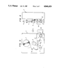
- FIG. 5 is a schematic front view of a preferred embodiment of a tape loading apparatus constructed according to the present invention.
- FIG. 6 is a schematic side view thereof
- FIG. 7 is an enlarged perspective view showing the vicinity of a tape reel depicted in FIG. 6;
- FIG. 8 is a block diagram showing the operation of the loading apparatus depicted in FIG. 6;
- FIGS. 9, 10, 11 and 12 are graphs showing respective patterns of tape speed and decompression
- FIG. 13 is a schematic front view of another embodiment of the tape loading apparatus of the present invention.
- FIG. 14 is a schematic side view thereof.
- FIG. 5 is a schematic front view of a preferred embodiment of a magnetic tape loading apparatus 1 constructed according to the invention
- FIG. 6 is a side view taken in the direction of an arrow A in FIG. 5.
- the loading apparatus 1 can be used in an open-reel winding method for winding a magnetic tape T on a pair of tape winding bodies 2 and 3 (hereinafter referred to as "tape reels") to be incorporated in a video cassette.
- the tape reels 2 and 3 are connected to each other through a leader tape 10 of a predetermined length (illustrated by half in FIG. 5).
- the leader tape 10 is cut about at its midpoint.
- the cut end of the part of the leader tape 10 connected to the tape reel 2 is bonded through a bonding tape or the like to a forward end of a raw magnetic tape 6.
- the magnetic tape T is wound through a predetermined length on the tape reel 2 and then is cut off, whereafter the cut end of the magnetic tape T wound on the tape reel 2 is bonded to the other end of the other part of the leader tape 10 connected to the tape reel 3.
- the cutting of the leader tape 10 and the magnetic tape T and the bonding between the leader tape 10 and the magnetic tape T are carried out by a cutting and bonding device 9, which includes a tape end holding member, a cutter, a bonding tape, etc.
- the magnetic tape T fed from the supply of raw tape 6, is wound on the tape reel 2 through a path 8 defined by guide pins and guide rollers.
- a magnet 19 is provided in the vicinity of the tape reel 2 disposed within a decompression chamber 50 connected to a vacuum pump 51. (The cutting and bonding device 9 and the vacuum pump 51 are now shown in FIG. 6 for clarity of illustration.)
- the magnet 19 may be shaped like a doughnut, as shown in FIG. 7, and attached to a body (front panel) of the apparatus by a nonmagnetic support 20 in such a manner that the magnet 19 surrounds the shaft 4. Accordingly, the magnetic tape T to be wound on the tape reel 2 is attracted by the action of the magnet 19 so that the magnetic tape T can be wound on the tape reel 2 while contacting a flange 2a.
- the magnet 19 may be a permanent magnet or an electromagnet.
- the decompression chamber 50 is formed so that the tape reel 2 can be mounted/demounted without hindrance.
- the decompression chamber 50 is formed so that smooth tape running, air-tightness and the like can be suitably maintained in its slit-like entrance portion through which the magnetic tape T enters the decompression chamber 50.
- the decompression chamber 50 is made as small in inside volume as possible to thereby realize rapid decompression.
- the shaft 4 for rotating the tape reel 2 is connected to a motor (not shown).
- the rotational speed of the shaft 4 and the decompression level of the decompression chamber 50 are suitably controlled by a control unit including a winding control circuit for controlling the rotational speed of the reel 2 and a decompression control circuit.
- the decompression control circuit detects the pressure of the decompression chamber 50 to thereby control the vacuum pump 51, a decompression chamber opening and shutting mechanism, etc., based on the detected results.
- the winding control circuit detects the speed and tension of the tape to thereby control the driving device, such as a motor or the like, which effects the tape winding, based on the detected results. Further, signal transmission is carried out between the decompression control circuit and the winding control circuit so that the tape speed and the decompression operation are substantially synchronized with each other.
- control sequence for the tape speed and the decompression can be carried out as follows.
- the decompression starts at about the same time as tape winding or even just after the start of tape winding.
- the decompression level is controlled to reach the main decompression level P 1 at the time t 1 when the tape winding speed V reaches the tape speed V 1 of the winding main speed area or just before the time t 1 .
- the winding appearance of the tape is maintained good by the action of the magnetic force of the magnet 19.
- the action of the magnetic force alone is sufficient to make the winding appearance good because the tape speed is low when the decompression level is low.
- the decompression level is maintained at the decompression level P 1 of the main decompression area.
- very high speed winding which could not be done in the prior art apparatus, can be realized by the combined action of the magnetic force and decompression.
- the tape speed is reduced to stop the tape (in interval C) and thereby complete the tape winding operation.
- the decompression level may be reduced (as shown by solid line in FIG. 9) at about the same time as the tape speed is reduced. In the case where the decompression chamber is opened to atmospheric pressure, the decompression level can be rapidly reduced.
- the decompression level may be held at the main decompression level P 1 , as shown by a broken line in FIG. 9, until just before the winding operation is completed at the time t 3 . Further, a good winding appearance can be obtained substantially by the action of the magnetic field in the interval C in the same manner as in the interval A.
- the present invention is not limited to the specific tape speed curve and decompression curve described above, and is not limited to the specific embodiment shown in FIG. 9.
- modifications can be made as shown in FIGS. 10, 11 and 12.
- the decompression curve of FIG. 10 is similar to that of FIG. 9, but in the tape speed curve of FIG. 10 the tape speed is not constant in the interval B, and a curve is drawn for the interval B based on the extension lines of acceleration and deceleration.
- the tape speed curve of FIG. 11 is similar to that of FIG. 9, except that in the decompression curve of FIG. 11 the decompression is not constant in the interval B and is kept higher than a predetermined decompression level.
- the tape speed curve of FIG. 12 is similar to that of FIG. 10, and the decompression curve of FIG. 12 is similar to that of FIG. 11.
- winding main speed area of the tape speed means the area of the tape speed not less than a specific speed (V 1 ).
- the specific speed V 1 is suitably determined by physcial properties of the tape, such as the thickness of the magnetic tape, the tape material, the decompression level, the strength of the magnetic field, and other conditions.
- main decompression level as used herein means the area of decompression not less than a specific decompression level (P 1 ).
- P 1 is also suitably determined by the physical properties of the tape, such as the thickness of the magnetic tape, the tape material, the tape speed, the strength of the magnetic field, and other conditions.
- the tape speed in the winding main speed area is not less than about 10 m/sec and the pressure in the main decompression area to be about half atmospheric pressure.
- FIG. 13 is a schematic front view of another embodiment of the invention, namely, an embodiment used with an incassette winding type magnetic tape loading apparatus
- FIG. 14 is a side view taken in the direction of an arrow A in FIG. 13.
- the loading apparatus 1 is used in a method for finishing a manufactured article by loading a magnetic tape T on a pair of tape reels 2 and 3 incorporated in a VHS- or BETA-type video tape cassette case.
- the cassette case 28 containing the tape reels 2 and 3 connected to each other through a leader tape 10 of a predetermined length is attached to a cassette holder 21 of the apparatus 1 and is held by the holder 21.
- the holder 21 moves through movable shafts 22, in the direction of an arrow B, so that drive shafts 4 and 5 are respectively fitted into the tape reels 2 and 3 from the lower side thereof.
- a guard panel (not shown) for closing a front portion of the cassette case 28 when the cassette is not in use is opened substantially in the same manner as in a general VTR cassette.
- the leader tape 10 is pulled out and cut off about at its midpoint.
- the cut end of the part of the leader tape 10 connected to the tape reel 2 is bonded through a bonding tape or the like to a forward end of a raw magnetic tape 6.
- the magnetic tape T is wound through a predetermined length of the tape reel 2 and then is cut off, whereafter the cut end of the magnetic tape T wound on the tape reel 2 is bonded to the other end of the other part of the leader tape 10 connected to the tape reel 3.
- the cassette holder 21 moves in the direction of an arrow C in FIG. 14 so that the guard panel is shut and, at the same time, the cassette case is released by the cassette holder 21.
- the cassette case can be removed by downward movement.
- the cutting of the leader tape 10 and the magnetic tape T and the bonding between the leader tape 10 and the magnetic tape T are carried out by a cutting and bonding device 9 provided with tape end holding members 10a and 10b, a cutter, a bonding tape, etc.
- the magnetic tape T fed from the supply of raw tape is wound on the tape reel 2 through a path defined by guide pins and guide rollers. (The cutting and bonding device 9 and the vacuum pump 51 are not shown in FIG. 14 for clarity of illustration.)
- the decompression chamber 50 connected to the vacuum pump 51 must of course at least be capable of accommodating the cassette holder.
- the magnet 19 for applying a magnetic field to the magnetic tape T is, for example, mounted at the upper (left in FIG. 14) side of the cassette holder 21.
- the form and size of the magnet 19 are not limited specifically as long as predetermined magnetic field can be applied to the magnetic tape T to be wound on the tape reel 2.
- the decompression chamber 50 must have an opening-and-shutting structure so that the tape reel 2 can be mounted/demounted without hindrance. Further, the decompression chamber 50 should be constructed so that smooth tape running, air-tightness and the like can be suitably maintained in its slit-like entrance portion through which the magnetic tape T enters the decompression chamber 50.
- the control unit may include a decompression control circuit for controlling the decompression level of the decompression chamber 50 and a winding control circuit for controlling the driving system, such as a shaft 4 and the like, to operate in the manner described above with respect to the previous embodiment.
- the control of the tape speed and decompression can be carried out in the same manner as illustrated in FIGS. 9 to 12.
- the decompression chamber 50 is somewhat larger, particularly in the case of an in-cassette winding type apparatus, compared to the case of an open-reel winding type apparatus.
- the interval between t 0 and t 1 and the interval between t 2 and t 3 is made larger, or, in other words, the time required for reducing the pressure of the decompression chamber and the time required for returning the pressure to atmospheric pressure are large due to the size of the decompression chamber.
- such lost time in the loading operation is eliminated, and, at the same time, the tape winding speed can be remarkably increased. Consequently, in accordance with the invention, the overall manufacturing efficiency of the cassette is improved.
- the magnetic force imposed by a magnetic field is applied to the magnetic tape in the direction of tape width, and the ambient air pressure is reduced by decompression while the magnetic tape is being wound. Accordingly, the loss of time encountered in the prior art apparatuses in reaching the desired decompresion level is eliminated by the action of the magnet to thereby shorten the total time required for the tape loading operation, compared with the prior art method using decompression alone. Further, the magnet can be reduced in size due to the combined action of decompression. In addition, a good winding appearance of the tape is assured.
- the invention provides a magnetic tape loading method and apparatus greatly improved in terms of the quality of the magnetic tape and the manufacturing efficiency of the tape loading process.
Landscapes
- Manufacturing Of Magnetic Record Carriers (AREA)
Abstract
Description
Claims (7)
Applications Claiming Priority (2)
| Application Number | Priority Date | Filing Date | Title |
|---|---|---|---|
| JP62-34659 | 1987-02-19 | ||
| JP62034659A JPH07118176B2 (en) | 1987-02-19 | 1987-02-19 | Magnetic tape winding method and device |
Publications (1)
| Publication Number | Publication Date |
|---|---|
| US4846420A true US4846420A (en) | 1989-07-11 |
Family
ID=12420568
Family Applications (1)
| Application Number | Title | Priority Date | Filing Date |
|---|---|---|---|
| US07/157,663 Expired - Lifetime US4846420A (en) | 1987-02-19 | 1988-02-19 | Magnetic tape loading method and apparatus |
Country Status (2)
| Country | Link |
|---|---|
| US (1) | US4846420A (en) |
| JP (1) | JPH07118176B2 (en) |
Cited By (1)
| Publication number | Priority date | Publication date | Assignee | Title |
|---|---|---|---|---|
| EP1069558A2 (en) * | 1999-07-14 | 2001-01-17 | Hewlett-Packard Company | Tape driving computer system |
Citations (1)
| Publication number | Priority date | Publication date | Assignee | Title |
|---|---|---|---|---|
| JPS51642A (en) * | 1974-06-24 | 1976-01-06 | Hitachi Ltd | SAIRISUTASEIGYO SOCHI |
Family Cites Families (2)
| Publication number | Priority date | Publication date | Assignee | Title |
|---|---|---|---|---|
| JPS55122271A (en) * | 1979-03-07 | 1980-09-19 | Kazuyoshi Kamiyama | Dressing winding method of kinds of tape |
| JPS6151642A (en) * | 1984-08-20 | 1986-03-14 | Matsushita Electric Ind Co Ltd | Magnetic tape winder |
-
1987
- 1987-02-19 JP JP62034659A patent/JPH07118176B2/en not_active Expired - Fee Related
-
1988
- 1988-02-19 US US07/157,663 patent/US4846420A/en not_active Expired - Lifetime
Patent Citations (1)
| Publication number | Priority date | Publication date | Assignee | Title |
|---|---|---|---|---|
| JPS51642A (en) * | 1974-06-24 | 1976-01-06 | Hitachi Ltd | SAIRISUTASEIGYO SOCHI |
Cited By (2)
| Publication number | Priority date | Publication date | Assignee | Title |
|---|---|---|---|---|
| EP1069558A2 (en) * | 1999-07-14 | 2001-01-17 | Hewlett-Packard Company | Tape driving computer system |
| EP1069558A3 (en) * | 1999-07-14 | 2002-03-13 | Hewlett-Packard Company, A Delaware Corporation | Tape driving computer system |
Also Published As
| Publication number | Publication date |
|---|---|
| JPH07118176B2 (en) | 1995-12-18 |
| JPS63204576A (en) | 1988-08-24 |
Similar Documents
| Publication | Publication Date | Title |
|---|---|---|
| US4789110A (en) | Method and device for winding magnetic tape using magnetic alignment | |
| US4932600A (en) | Method for winding magnetic tape | |
| US4846420A (en) | Magnetic tape loading method and apparatus | |
| EP0194149B1 (en) | Magnetic tape recording apparatus | |
| US4909455A (en) | Method and device for winding magnetic tape using magnetic alignment | |
| US4863110A (en) | Magnetic tape winding method and apparatus | |
| US4838496A (en) | Magnetic tape loading method and apparatus | |
| US4842210A (en) | Method and device for winding magnetic tape using magnetic alignment | |
| JPH0582672B2 (en) | ||
| US5261621A (en) | Method and apparatus for evenly winding magnetic tape | |
| US4817884A (en) | Method and device for winding magnetic tape using magnetic alignment | |
| US4828197A (en) | Method and device for winding magnetic tape using magnetic alignment | |
| US4796824A (en) | Device for winding magnetic tape using magnetic alignment | |
| EP0223973B1 (en) | Method and apparatus for evenly winding magnetic tape | |
| US4828196A (en) | Device for winding magnetic tape using magnetic alignment | |
| JPH0582673B2 (en) | ||
| EP0232811A2 (en) | Method and device for winding magnetic tape using magnetic alignment | |
| JPH02101631A (en) | Magnetic tape take-up method | |
| JPS63298817A (en) | Method and apparatus for winding magnetic tape | |
| JPH0580758B2 (en) | ||
| JPH0582674B2 (en) | ||
| JPS62180576A (en) | Taking up method and device for magnetic tape | |
| JPS5945651A (en) | Sound recording and reproducing device | |
| JPS62281179A (en) | Magnetic tape take-up device | |
| JPS62281177A (en) | Magnetic tape take-up device |
Legal Events
| Date | Code | Title | Description |
|---|---|---|---|
| AS | Assignment |
Owner name: FUJI PHOTO FILM CO., LTD., NO. 210, NAKANUMA, MINA Free format text: ASSIGNMENT OF ASSIGNORS INTEREST.;ASSIGNORS:SAKAGUCHI, MASAAKI;USUI, MITSUNOBU;REEL/FRAME:004852/0133 Effective date: 19880128 Owner name: FUJI PHOTO FILM CO., LTD., JAPAN Free format text: ASSIGNMENT OF ASSIGNORS INTEREST;ASSIGNORS:SAKAGUCHI, MASAAKI;USUI, MITSUNOBU;REEL/FRAME:004852/0133 Effective date: 19880128 |
|
| STCF | Information on status: patent grant |
Free format text: PATENTED CASE |
|
| FEPP | Fee payment procedure |
Free format text: PAYOR NUMBER ASSIGNED (ORIGINAL EVENT CODE: ASPN); ENTITY STATUS OF PATENT OWNER: LARGE ENTITY |
|
| FPAY | Fee payment |
Year of fee payment: 4 |
|
| FEPP | Fee payment procedure |
Free format text: PAYER NUMBER DE-ASSIGNED (ORIGINAL EVENT CODE: RMPN); ENTITY STATUS OF PATENT OWNER: LARGE ENTITY Free format text: PAYOR NUMBER ASSIGNED (ORIGINAL EVENT CODE: ASPN); ENTITY STATUS OF PATENT OWNER: LARGE ENTITY |
|
| FPAY | Fee payment |
Year of fee payment: 8 |
|
| FEPP | Fee payment procedure |
Free format text: PAYER NUMBER DE-ASSIGNED (ORIGINAL EVENT CODE: RMPN); ENTITY STATUS OF PATENT OWNER: LARGE ENTITY Free format text: PAYOR NUMBER ASSIGNED (ORIGINAL EVENT CODE: ASPN); ENTITY STATUS OF PATENT OWNER: LARGE ENTITY |
|
| FPAY | Fee payment |
Year of fee payment: 12 |
|
| AS | Assignment |
Owner name: FUJIFILM CORPORATION, JAPAN Free format text: ASSIGNMENT OF ASSIGNORS INTEREST;ASSIGNOR:FUJIFILM HOLDINGS CORPORATION (FORMERLY FUJI PHOTO FILM CO., LTD.);REEL/FRAME:020817/0190 Effective date: 20080225 Owner name: FUJIFILM CORPORATION,JAPAN Free format text: ASSIGNMENT OF ASSIGNORS INTEREST;ASSIGNOR:FUJIFILM HOLDINGS CORPORATION (FORMERLY FUJI PHOTO FILM CO., LTD.);REEL/FRAME:020817/0190 Effective date: 20080225 |