US4817046A - Detection of engine failure in a multi-engine aircraft - Google Patents
Detection of engine failure in a multi-engine aircraft Download PDFInfo
- Publication number
- US4817046A US4817046A US06/849,983 US84998386A US4817046A US 4817046 A US4817046 A US 4817046A US 84998386 A US84998386 A US 84998386A US 4817046 A US4817046 A US 4817046A
- Authority
- US
- United States
- Prior art keywords
- engine
- local
- threshold
- gas generator
- sensing whether
- Prior art date
- Legal status (The legal status is an assumption and is not a legal conclusion. Google has not performed a legal analysis and makes no representation as to the accuracy of the status listed.)
- Expired - Lifetime
Links
- 238000001514 detection method Methods 0.000 title abstract description 4
- 238000000034 method Methods 0.000 claims description 7
- 230000003247 decreasing effect Effects 0.000 claims description 5
- 230000011664 signaling Effects 0.000 claims description 3
- 230000009977 dual effect Effects 0.000 abstract description 6
- 239000000446 fuel Substances 0.000 description 1
- 230000035945 sensitivity Effects 0.000 description 1
- 230000000007 visual effect Effects 0.000 description 1
Images
Classifications
-
- F—MECHANICAL ENGINEERING; LIGHTING; HEATING; WEAPONS; BLASTING
- F02—COMBUSTION ENGINES; HOT-GAS OR COMBUSTION-PRODUCT ENGINE PLANTS
- F02D—CONTROLLING COMBUSTION ENGINES
- F02D45/00—Electrical control not provided for in groups F02D41/00 - F02D43/00
-
- G—PHYSICS
- G05—CONTROLLING; REGULATING
- G05D—SYSTEMS FOR CONTROLLING OR REGULATING NON-ELECTRIC VARIABLES
- G05D1/00—Control of position, course, altitude or attitude of land, water, air or space vehicles, e.g. using automatic pilots
- G05D1/0055—Control of position, course, altitude or attitude of land, water, air or space vehicles, e.g. using automatic pilots with safety arrangements
- G05D1/0072—Control of position, course, altitude or attitude of land, water, air or space vehicles, e.g. using automatic pilots with safety arrangements to counteract a motor failure
-
- F—MECHANICAL ENGINEERING; LIGHTING; HEATING; WEAPONS; BLASTING
- F02—COMBUSTION ENGINES; HOT-GAS OR COMBUSTION-PRODUCT ENGINE PLANTS
- F02C—GAS-TURBINE PLANTS; AIR INTAKES FOR JET-PROPULSION PLANTS; CONTROLLING FUEL SUPPLY IN AIR-BREATHING JET-PROPULSION PLANTS
- F02C9/00—Controlling gas-turbine plants; Controlling fuel supply in air- breathing jet-propulsion plants
- F02C9/26—Control of fuel supply
- F02C9/28—Regulating systems responsive to plant or ambient parameters, e.g. temperature, pressure, rotor speed
-
- F—MECHANICAL ENGINEERING; LIGHTING; HEATING; WEAPONS; BLASTING
- F02—COMBUSTION ENGINES; HOT-GAS OR COMBUSTION-PRODUCT ENGINE PLANTS
- F02C—GAS-TURBINE PLANTS; AIR INTAKES FOR JET-PROPULSION PLANTS; CONTROLLING FUEL SUPPLY IN AIR-BREATHING JET-PROPULSION PLANTS
- F02C9/00—Controlling gas-turbine plants; Controlling fuel supply in air- breathing jet-propulsion plants
- F02C9/26—Control of fuel supply
- F02C9/42—Control of fuel supply specially adapted for the control of two or more plants simultaneously
-
- F—MECHANICAL ENGINEERING; LIGHTING; HEATING; WEAPONS; BLASTING
- F05—INDEXING SCHEMES RELATING TO ENGINES OR PUMPS IN VARIOUS SUBCLASSES OF CLASSES F01-F04
- F05D—INDEXING SCHEME FOR ASPECTS RELATING TO NON-POSITIVE-DISPLACEMENT MACHINES OR ENGINES, GAS-TURBINES OR JET-PROPULSION PLANTS
- F05D2270/00—Control
- F05D2270/01—Purpose of the control system
- F05D2270/09—Purpose of the control system to cope with emergencies
Definitions
- a multi-engine aircraft such as a helicopter
- commonly-owned U.S. Pat. No. 4,500,966 discloses super contingency aircraft engine control in response to an engine failure.
- primary logic for engine failure detection in a multi-engine aircraft is based on thresholds for engine torque (Q), gas generator speed (NG), power turbine inner stage temperature (T5), power turbine speed (NF), throttle setting (PLA), and throttle manipulation (PLADOT).
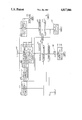
- FIG. 1 is a flowchart of the software routine for implementing the invention is an electronic engine control.
- Electronic engine controls that maintain preset engine operating characteristics and/or maintain engine operation within preset limits are well known.
- NG gas generator speed
- NF free turbine speed
- T5 power turbine inner stage temperature
- Q engine output torque
- WF fuel flow
- CLP collective
- PPA power lever or throttle
- the invention is described in the context of a two-engine helicopter, such as the Sikorsky S-76B.
- the overall function of the system is to detect, both reliably and rapidly, conditions indicative of an engine failure, and to provide suitable inputs to an electronic engine control for operating the remaining engine.
- a cockpit indication of engine failure is also provided.
- the basic engine failure diagnostic routine of this invention is described in FIG. 1.
- the routine is accessed at a step 100, and is applicable to each engine.
- a local engine and a remote engine are discussed.
- Four subroutines 200, 300, 400, and 500 are then simultaneously processed.
- the subroutine 200 it is determined at a step 202 whether the power lever angle (PLA) for the local engine is greater than 30°, and at a step 204 it is determined whether the gas generator speed (NG) for the local engine is less than or equal to 48%.
- PPA power lever angle
- NG gas generator speed
- the conditions in the step 102 are:
- PPA Power Lever Angle
- bypass conditions are met, the routine is exited and reentered at the step 100. If the bypass conditions are not satisfied, an EFAIL flag is set to ONE at a step 130.
- a visual and/or aural warning indicate to the pilot that the local engine has failed.
- the gain of the power turbine speed governing loop for the remote engine is doubled to boost the torque required to maintain the power turbine speed in the remote engine. (In a three engine situation, the gains in the two remote engines would be increased by 3/2.)
- the torque limit, NG limit, and T5 limit in the electronic engine control for the remote engine(s) are increased to assure power available in the remote engine(s) for a safe landing. If the failure logic could be made absolutely fail-safe, the local engine could be shut down by the routine at this point.
- step 100 the routine is exited, and reentered at the step 100.
- the routine is also reentered at the step 100 if the results of either step 202,204 are negative.
- a step 302 it is determined at a step 302 whether the power lever angle (PLA) for the local engine is greater than 48°, at a step 304 whether the gas generator speed (NG) for the local engine is less than or equal to 52 percent, and at a step 306 whether the rate of change in gas generator speed (NGDOT) for the local engine is negative. If all three conditions are satisfied, a first counter (timer) is incremented at a step 126, and at a step 128 it is determined whether the first counter has timed out to 0.2 seconds. If so, the bypass conditions are checked in the step 102. If not, the routine is reentered at the step 100.
- PPA power lever angle
- NG gas generator speed
- NGDOT rate of change in gas generator speed
- step 138 it is determined in a step 138 whether the EFAIL flag is ONE. If it is not, in a step 104 the EFAIL flag is set to zero, the first counter is set to zero, and a second counter (timer) is set to zero. Then, the routine is exited and reentered at the step 100.
- step 508 it is determined in a step 508 whether the second counter has timed out to 0.2 seconds. If it has, the routine proceeds to the step 104. If it has not, the routine is exited and reentered at the step 100.
- the subroutine 500 consists of steps 502 and 504. In the step 502 it is determined whether the rate of change in gas generator speed (NGDOT) for the local engine is positive. In the step 504 it is determined whether the gas generator speed (NG) for the local engine is at least a threshold speed of 57 percent. If both test results are positive, the second counter is incremented at the step 506, and at the step 508 it is determined whether the second counter has timed out. If either of the test 502,504 results are negative, the second counter is set to zero at a step 510, and the routine is exited and reentered at the step 100.
- the subroutine 500 allows a return to dual engine control if on the previous pass (cycle of the routine) a failure for the local engine has been falsely indicated.
- the steps 402-412 are performed.
- PPA power lever angle
- step 404 it is determined whether the torque split between the local engine (QLOC) and the remote engine (QRMT) is above a threshold of 20%.
- step 406 it is determined whether the rate of change in the gas generator speed (NGDOT) for the local engine is decelerating faster than a threshold of 5%/second.
- step 408 it is determined whether the rate of change of power turbine inner stage temperature for the remote engine (DT5RMT) is increasing, steady, or decreasing slightly (i.e., not more than 30° C./second).
- step 410 it is determined whether the power turbine speed (NF) for the local engine is at least within a threshold, such as 1 percent of its reference speed (NFREF), as established in the electronic engine control.
- a threshold such as 1 percent of its reference speed (NFREF)
- the absolute value of the rate of change for the power lever angle associated with the local engine is less than a threshold, such as 2°/second, which is indicative of no advertent pilot manipulation of the power lever in either direction. (Advertent manipulation of the power lever could provoke indications of an engine failure.)
- step 402-412 determines whether the results of the step 402-412 are all positive. If the results of the step 402-412 are all positive, the routine proceeds to the step 126. If not, the routine proceeds to the step 138 wherein it is determined whether the EFAIL flag is one. If it is, the routine proceeds to the step 508. If it is not, the routine proceeds to the step 104.
- the above-described logic does not detect a simultaneous dual engine failure. Nor does it detect a remaining engine failure, since there would be no torque split (step 404).
- the subroutine 200 is a back-up to the primary logic of the subroutine 400 and also provides basic engine out indication for loss of the remaining engine.
- the subroutine 300 improves the detection (ratio) time required for engine failures at low powers (partial power descents and autorotation where the engine is at flight idle) where other indications (Q split) are not apparent.
Landscapes
- Engineering & Computer Science (AREA)
- Chemical & Material Sciences (AREA)
- Combustion & Propulsion (AREA)
- Mechanical Engineering (AREA)
- General Engineering & Computer Science (AREA)
- Radar, Positioning & Navigation (AREA)
- Aviation & Aerospace Engineering (AREA)
- Remote Sensing (AREA)
- Physics & Mathematics (AREA)
- General Physics & Mathematics (AREA)
- Automation & Control Theory (AREA)
- Combined Controls Of Internal Combustion Engines (AREA)
- Control Of Vehicle Engines Or Engines For Specific Uses (AREA)
- Control Of Eletrric Generators (AREA)
Abstract
Description
Claims (6)
Priority Applications (4)
| Application Number | Priority Date | Filing Date | Title |
|---|---|---|---|
| US06/849,983 US4817046A (en) | 1986-04-10 | 1986-04-10 | Detection of engine failure in a multi-engine aircraft |
| BE8700360A BE1002395A4 (en) | 1986-04-10 | 1987-04-07 | DETECTION OF AN ENGINE FAILURE ON A MULTI-ENGINE AIRPLANE. |
| TR25787A TR23667A (en) | 1986-04-10 | 1987-04-08 | Engine failure in a multi-engine aerial vehicle. |
| KR1019870003414A KR950004611B1 (en) | 1986-04-10 | 1987-04-10 | Detection of engine failure in a multi-engine aircraft |
Applications Claiming Priority (1)
| Application Number | Priority Date | Filing Date | Title |
|---|---|---|---|
| US06/849,983 US4817046A (en) | 1986-04-10 | 1986-04-10 | Detection of engine failure in a multi-engine aircraft |
Publications (1)
| Publication Number | Publication Date |
|---|---|
| US4817046A true US4817046A (en) | 1989-03-28 |
Family
ID=25306977
Family Applications (1)
| Application Number | Title | Priority Date | Filing Date |
|---|---|---|---|
| US06/849,983 Expired - Lifetime US4817046A (en) | 1986-04-10 | 1986-04-10 | Detection of engine failure in a multi-engine aircraft |
Country Status (4)
| Country | Link |
|---|---|
| US (1) | US4817046A (en) |
| KR (1) | KR950004611B1 (en) |
| BE (1) | BE1002395A4 (en) |
| TR (1) | TR23667A (en) |
Cited By (11)
| Publication number | Priority date | Publication date | Assignee | Title |
|---|---|---|---|---|
| WO1993006539A1 (en) * | 1991-09-19 | 1993-04-01 | Allied-Signal Inc. | Method and apparatus for determining the phase difference between two input signals |
| WO1994010619A1 (en) * | 1992-10-29 | 1994-05-11 | United Technologies Corporation | Partial engine and driveshaft failure detection monitor for a multi-engine aircraft |
| US5551227A (en) * | 1994-12-22 | 1996-09-03 | General Electric Company | System and method of detecting partial flame out in a gas turbine engine combustor |
| EP1447544A1 (en) * | 2003-01-21 | 2004-08-18 | Rolls-Royce Deutschland Ltd & Co KG | Failure detection logic for gas turbine engines |
| US20060174629A1 (en) * | 2004-08-24 | 2006-08-10 | Honeywell International, Inc | Method and system for coordinating engine operation with electrical power extraction in a more electric vehicle |
| US20080275597A1 (en) * | 2006-06-19 | 2008-11-06 | Eurocopter | Balancing the power of two turboshaft engines of an aircraft |
| US20090186320A1 (en) * | 2008-01-23 | 2009-07-23 | John Rucci | Modules and methods for biasing power to a multi-engine power plant suitable for one engine inoperative flight procedure training |
| US8930120B2 (en) | 2010-06-14 | 2015-01-06 | Inha-Industry Partnership Institute | System for fault detection and diagnosis of aircraft engine and method thereof |
| RU2565163C2 (en) * | 2012-11-26 | 2015-10-20 | Эйрбас Хеликоптерс | Method and flying vehicle with rotor equipped with three engine |
| US20170159574A1 (en) * | 2015-12-04 | 2017-06-08 | General Electric Company | Adaptive Engine Model Torque Splitting Optimization |
| US20170300065A1 (en) * | 2016-04-18 | 2017-10-19 | Latitude Engineering, LLC | Automatic recovery systems and methods for unmanned aircraft systems |
Citations (8)
| Publication number | Priority date | Publication date | Assignee | Title |
|---|---|---|---|---|
| US4218878A (en) * | 1978-04-28 | 1980-08-26 | Westinghouse Electric Corp. | Acceleration monitoring system for protecting gas turbine against damaging operation at resonant speeds |
| US4423593A (en) * | 1982-04-16 | 1984-01-03 | Chandler Evans Inc. | Fuel control for controlling helicopter rotor/turbine acceleration |
| US4454754A (en) * | 1982-05-26 | 1984-06-19 | Chandler Evans, Inc. | Engine failure detector |
| US4488236A (en) * | 1982-04-16 | 1984-12-11 | United Technologies Corporation | Helicopter cruise fuel conserving engine control |
| US4493465A (en) * | 1982-04-16 | 1985-01-15 | Chandler Evans Inc. | Helicopter engine torque compensator |
| US4500966A (en) * | 1982-05-26 | 1985-02-19 | Chandler Evans Inc. | Super contingency aircraft engine control |
| US4546353A (en) * | 1984-02-06 | 1985-10-08 | The United States Of America As Represented By The Secretary Of The Air Force | Asymmetric thrust warning system for dual engine aircraft |
| US4619110A (en) * | 1983-07-13 | 1986-10-28 | Moore M Samuel | Helicopter engine warning or control system |
Family Cites Families (2)
| Publication number | Priority date | Publication date | Assignee | Title |
|---|---|---|---|---|
| US3979579A (en) * | 1975-05-19 | 1976-09-07 | Lawrence Peska Associates, Inc. | Aircraft engine fatigue cycle recorder |
| US4651563A (en) * | 1985-10-16 | 1987-03-24 | Sperry Corporation | Jet engine testing apparatus |
-
1986
- 1986-04-10 US US06/849,983 patent/US4817046A/en not_active Expired - Lifetime
-
1987
- 1987-04-07 BE BE8700360A patent/BE1002395A4/en not_active IP Right Cessation
- 1987-04-08 TR TR25787A patent/TR23667A/en unknown
- 1987-04-10 KR KR1019870003414A patent/KR950004611B1/en not_active IP Right Cessation
Patent Citations (8)
| Publication number | Priority date | Publication date | Assignee | Title |
|---|---|---|---|---|
| US4218878A (en) * | 1978-04-28 | 1980-08-26 | Westinghouse Electric Corp. | Acceleration monitoring system for protecting gas turbine against damaging operation at resonant speeds |
| US4423593A (en) * | 1982-04-16 | 1984-01-03 | Chandler Evans Inc. | Fuel control for controlling helicopter rotor/turbine acceleration |
| US4488236A (en) * | 1982-04-16 | 1984-12-11 | United Technologies Corporation | Helicopter cruise fuel conserving engine control |
| US4493465A (en) * | 1982-04-16 | 1985-01-15 | Chandler Evans Inc. | Helicopter engine torque compensator |
| US4454754A (en) * | 1982-05-26 | 1984-06-19 | Chandler Evans, Inc. | Engine failure detector |
| US4500966A (en) * | 1982-05-26 | 1985-02-19 | Chandler Evans Inc. | Super contingency aircraft engine control |
| US4619110A (en) * | 1983-07-13 | 1986-10-28 | Moore M Samuel | Helicopter engine warning or control system |
| US4546353A (en) * | 1984-02-06 | 1985-10-08 | The United States Of America As Represented By The Secretary Of The Air Force | Asymmetric thrust warning system for dual engine aircraft |
Cited By (17)
| Publication number | Priority date | Publication date | Assignee | Title |
|---|---|---|---|---|
| WO1993006539A1 (en) * | 1991-09-19 | 1993-04-01 | Allied-Signal Inc. | Method and apparatus for determining the phase difference between two input signals |
| US5291410A (en) * | 1991-09-19 | 1994-03-01 | Allied-Signal Inc. | Circuitry for synchronizing the speed of a plurality of engines by sequentially averaging phase difference with a reference phase representing a desired speed |
| WO1994010619A1 (en) * | 1992-10-29 | 1994-05-11 | United Technologies Corporation | Partial engine and driveshaft failure detection monitor for a multi-engine aircraft |
| US5363317A (en) * | 1992-10-29 | 1994-11-08 | United Technologies Corporation | Engine failure monitor for a multi-engine aircraft having partial engine failure and driveshaft failure detection |
| US5551227A (en) * | 1994-12-22 | 1996-09-03 | General Electric Company | System and method of detecting partial flame out in a gas turbine engine combustor |
| US7184865B2 (en) | 2003-01-21 | 2007-02-27 | Rolls-Royce Deutschland Ltd & Co Kg | Fault detection logic for engines |
| US20050071072A1 (en) * | 2003-01-21 | 2005-03-31 | Torsten Mangelsdorf | Fault detection logic for engines |
| EP1447544A1 (en) * | 2003-01-21 | 2004-08-18 | Rolls-Royce Deutschland Ltd & Co KG | Failure detection logic for gas turbine engines |
| US20060174629A1 (en) * | 2004-08-24 | 2006-08-10 | Honeywell International, Inc | Method and system for coordinating engine operation with electrical power extraction in a more electric vehicle |
| US20080275597A1 (en) * | 2006-06-19 | 2008-11-06 | Eurocopter | Balancing the power of two turboshaft engines of an aircraft |
| US9346553B2 (en) * | 2006-06-19 | 2016-05-24 | Airbus Helicopters | Balancing the power of two turboshaft engines of an aircraft |
| US20090186320A1 (en) * | 2008-01-23 | 2009-07-23 | John Rucci | Modules and methods for biasing power to a multi-engine power plant suitable for one engine inoperative flight procedure training |
| US9355571B2 (en) | 2008-01-23 | 2016-05-31 | Sikorsky Aircraft Corporation | Modules and methods for biasing power to a multi-engine power plant suitable for one engine inoperative flight procedure training |
| US8930120B2 (en) | 2010-06-14 | 2015-01-06 | Inha-Industry Partnership Institute | System for fault detection and diagnosis of aircraft engine and method thereof |
| RU2565163C2 (en) * | 2012-11-26 | 2015-10-20 | Эйрбас Хеликоптерс | Method and flying vehicle with rotor equipped with three engine |
| US20170159574A1 (en) * | 2015-12-04 | 2017-06-08 | General Electric Company | Adaptive Engine Model Torque Splitting Optimization |
| US20170300065A1 (en) * | 2016-04-18 | 2017-10-19 | Latitude Engineering, LLC | Automatic recovery systems and methods for unmanned aircraft systems |
Also Published As
| Publication number | Publication date |
|---|---|
| BE1002395A4 (en) | 1991-01-29 |
| TR23667A (en) | 1990-06-04 |
| KR950004611B1 (en) | 1995-05-03 |
| KR870010298A (en) | 1987-11-30 |
Similar Documents
| Publication | Publication Date | Title |
|---|---|---|
| US5363317A (en) | Engine failure monitor for a multi-engine aircraft having partial engine failure and driveshaft failure detection | |
| US4500966A (en) | Super contingency aircraft engine control | |
| US5313778A (en) | Automatic turbine engine bleed valve control for enhanced fuel management | |
| US6880784B1 (en) | Automatic takeoff thrust management system | |
| US4454754A (en) | Engine failure detector | |
| US4817046A (en) | Detection of engine failure in a multi-engine aircraft | |
| US5225829A (en) | Independent low airspeed alert | |
| US8798810B2 (en) | Energy protecting device for aircraft | |
| CA1198191A (en) | Helicopter engine control with rotor speed decay anticipator | |
| US8504222B2 (en) | Emergency descent intervention system | |
| EP0219348B1 (en) | Jet engine testing apparatus | |
| US11597526B2 (en) | Control systems for hybrid electric powerplants | |
| US4884205A (en) | Method and apparatus for limiting adverse yaw-induced roll during engine failure in multiengine aircraft | |
| JPH06510253A (en) | Helicopter engine speed increase during high rotor load and rapid descent speed operations | |
| US4218879A (en) | Overspeed protection device | |
| US4662171A (en) | Automatic thrust restoration system | |
| US4609987A (en) | Aircraft guidance system for take off or go-around during severe wind shear | |
| US5020316A (en) | Helicopter control with multiple schedule rotor speed decay anticipator | |
| CA1290058C (en) | Autofeather state machine | |
| US2959228A (en) | Torque responsive propeller control | |
| IL72461A (en) | Rotorcraft load factor enhancer | |
| RU2306446C1 (en) | Method of control of aircraft power plant | |
| US3145953A (en) | Aircraft | |
| Arnold et al. | One Engine Inoperative Takeoff Climb Performance of the XV-15 Tilt Rotor | |
| Picasso III et al. | Airworthiness and Flight Characteristics (A&FC) Test of YAH-64 Advanced Attack Helicopter, Prototype Qualification Test-Government (PQTG), Part 3 and Production Validation Test-Government (PVTG) for Handbook Verification |
Legal Events
| Date | Code | Title | Description |
|---|---|---|---|
| AS | Assignment |
Owner name: UNITED TECHNOLOGIES CORPORATION, HARTFORD, CONNECT Free format text: ASSIGNMENT OF ASSIGNORS INTEREST.;ASSIGNORS:RICE, ROBERT W.;SWEET, DAVID H.;EVANS, CHARLES W.;AND OTHERS;REEL/FRAME:004570/0941;SIGNING DATES FROM 19860410 TO 19860418 |
|
| STCF | Information on status: patent grant |
Free format text: PATENTED CASE |
|
| FPAY | Fee payment |
Year of fee payment: 4 |
|
| FPAY | Fee payment |
Year of fee payment: 8 |
|
| FEPP | Fee payment procedure |
Free format text: PAYOR NUMBER ASSIGNED (ORIGINAL EVENT CODE: ASPN); ENTITY STATUS OF PATENT OWNER: LARGE ENTITY |
|
| FPAY | Fee payment |
Year of fee payment: 12 |