US4814709A - Method of selecting specific region of sample - Google Patents
Method of selecting specific region of sample Download PDFInfo
- Publication number
- US4814709A US4814709A US07/059,879 US5987987A US4814709A US 4814709 A US4814709 A US 4814709A US 5987987 A US5987987 A US 5987987A US 4814709 A US4814709 A US 4814709A
- Authority
- US
- United States
- Prior art keywords
- sample
- magnetic field
- spins
- static magnetic
- specific region
- Prior art date
- Legal status (The legal status is an assumption and is not a legal conclusion. Google has not performed a legal analysis and makes no representation as to the accuracy of the status listed.)
- Expired - Lifetime
Links
Images


Classifications
-
- G—PHYSICS
- G01—MEASURING; TESTING
- G01R—MEASURING ELECTRIC VARIABLES; MEASURING MAGNETIC VARIABLES
- G01R33/00—Arrangements or instruments for measuring magnetic variables
- G01R33/20—Arrangements or instruments for measuring magnetic variables involving magnetic resonance
- G01R33/44—Arrangements or instruments for measuring magnetic variables involving magnetic resonance using nuclear magnetic resonance [NMR]
- G01R33/48—NMR imaging systems
- G01R33/483—NMR imaging systems with selection of signals or spectra from particular regions of the volume, e.g. in vivo spectroscopy
- G01R33/4838—NMR imaging systems with selection of signals or spectra from particular regions of the volume, e.g. in vivo spectroscopy using spatially selective suppression or saturation of MR signals
-
- G—PHYSICS
- G01—MEASURING; TESTING
- G01R—MEASURING ELECTRIC VARIABLES; MEASURING MAGNETIC VARIABLES
- G01R33/00—Arrangements or instruments for measuring magnetic variables
- G01R33/20—Arrangements or instruments for measuring magnetic variables involving magnetic resonance
- G01R33/44—Arrangements or instruments for measuring magnetic variables involving magnetic resonance using nuclear magnetic resonance [NMR]
- G01R33/48—NMR imaging systems
- G01R33/4818—MR characterised by data acquisition along a specific k-space trajectory or by the temporal order of k-space coverage, e.g. centric or segmented coverage of k-space
- G01R33/482—MR characterised by data acquisition along a specific k-space trajectory or by the temporal order of k-space coverage, e.g. centric or segmented coverage of k-space using a Cartesian trajectory
Definitions
- This invention relates to a method of selecting a specific region of a sample, and more particularly to a method of selecting a specific region of a sample which is suitable for NMR (nuclear magnetic resonance) imaging.
- the atomic nuclei When a sample having atomic nuclei whose spin quantitization number is not zero is placed in a static magnetic field, the atomic nuclei exhibit a macro behaviour as an aggregate and can be regarded as a magnetization vector having magnetization in parallel with the direction of the static magnetic field and angular momentum.
- the relation between a magnetic moment ⁇ representing the magnitude of magnetization and the angular momentum J is expressed as follows with ⁇ representing a gyromagnetic ratio:
- Eq. (3) can be expressed as follows by a coordinate system rotating at an angular velocity ⁇ : ##EQU3##
- the direction of the static magnetic field H 0 is called “Z” and directions orthogonal thereto are "X, Y” and a magnetic field H 1 is applied from the X direction (this means a radio frequency magnetic field rotating at ⁇ 0 ), the magnetization vector rotates on the Z - Y plane at an angular velocity expressed by ⁇ H 1 .
- a magnetic field H 1 which is applied until the magnetization vector is 90° relative to the Z axis (falls on the X - Y plane) is referred to as "90° pulse”, and "180° pulse” is defined similarly.
- the component of the X - Y plane of the magnetization vector is induced as a signal in a coil disposed on the X - Y plane.
- This method is excellent to selectively obtain a signal in a uni-dimensional direction.
- this method cannot be applied a plurality of times in order to make selections a plurality of times and to obtain spatial information on regions of a plurality of dimensions.
- selection for obtaining the spatial information of two or more dimensions cannot be made.
- Another conventional method picks up selectively only the frequency components f 1 ⁇ f 2 corresponding to the specific region by bringing down by 90° the magnetization vectors for a wide range including the specific region x 1 ⁇ x 2 , then applying the gradient magnetic field and controlling the frequency band of the resulting signal.
- This method is a so-called "frequency filter system” and includes a system by use of an analog filter and a system using a digital filter in a narrow sense of the word.
- the analog filter has the disadvantage that the frequency band cannot be changed arbitrarily. Furthermore, its expansion to the spatial selection of two or more dimensions is not possible.
- the digital filter includes a digital filter in a narrow sense (that is, an ordinary digital filter system utilizing fold-in) and a filter utilizing Fourier transform.
- the digital filter in a narrow sense has the advantage that the frequency band can be changed arbitrarily, but its expansion to two or more dimensions is not possible in the same way as the analog filter.
- a data sampling period t int for digitizing the signal must satisfy the following condition from the Nyquist's theorem: ##EQU4## where f max is a maximum frequency contained in the signal.
- a sampling rate is determined by the signal band of the excited signal quite irrelevantly to the frequency band that corresponds to the specific region.
- the filter utilizing Fourier transform samples the signal, converts it to a digital signal, subjects altogether the sampled data to Fourier transform and picks up only the data of the object frequency band (f 1 ⁇ f 2 ) from the resulting data.
- This Fourier transform method can separate the spatial information of multiple dimensions by skilfully utilizing the principle of nuclear magnetic resonance such as two-dimensional Fourier transform imaging method and three-dimensional Fourier transform imaging method, and moreover, arbitrary filtration is possible in principle.
- This method collects only the data relating to the specific data and discards the rest from the data obtained by ordinary processing. Therefore, this method is excellent in that any particular processing is not necessary.
- the condition of the sampling rate expressed by the equation (7) must be satisfied.
- the data acquisition time T aq must satisfy the following condition in order to obtain resolution ⁇ f: ##EQU5## Therefore, the number of data points N is given as follows from eq. (7) and (8): ##EQU6## If the frequency band corresponding to the object space is f 0 max resolution is ⁇ f 0 , the necessary data point number N is given as follows: ##EQU7## When the ratio of eq. (9) to eq. (10) is obtained, ##EQU8##
- the present invention is directed to provide a method of selecting a specific region of a sample which is suitable for obtaining multidimensional spatial information.
- a method of selecting a specific region of a sample which includes the steps of arranging a sample in a static magnetic field so that the spin in the sample is oriented parallel to the static magnetic field, bringing down the spin of the sample in the specific region in a direction at right angles to the static magnetic field and then orienting it parallel to the static magnetic field so that the spin of the sample in regions other than the specific region is brought down in a direction at right angles to the static magnetic field, and making non-uniform the static magnetic field so that the spin of the sample in the regions other than the specific region becomes saturated.
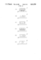
- FIG. 1 is a block diagram of a nuclear magnetic resonance imaging apparatus for practising the method of the present invention in accordance with one embodiment thereof;
- FIG. 2 is a perspective view showing the state of arrangement of a sample in a static magnetic field
- FIG. 3(A) is a schematic view showing the first state of magnetization vector of the sample
- FIG. 3(B) is a schematic view showing the second state of the magnetization vector of the sample
- FIG. 3(C) is a schematic view showing the third state of the magnetization vector of the sample.
- FIG. 3(D) is a schematic view showing the fourth state of the magnetization vector of the sample.
- FIG. 3(E) is a schematic view showing the fifth state of the vector of the sample.
- FIG. 3(F) is a schematic view showing the sixth state of the vector of the sample.
- FIG. 4 is a time chart of a first embodiment of the method of the present invention.
- FIG. 5 is a time chart of a second embodiment of the present method.
- FIG. 6 is a time chart of a third embodiment of the present method.
- FIG. 7 is a time chart of a fourth embodiment of the present method.
- FIG. 8 is a time chart of a fifth embodiment of the present method.
- FIG. 9 is a time chart of a sixth embodiment of the present method.
- FIG. 10 is a perspective view showing the state of arrangement of the sample and useful for explaining an application example of the present method.
- a current is supplied from a magnet power source 12 to a magnet 10 to generate a uniform static magnetic field H 0 .
- a sample 16 is disposed at the center of the magnet 10.
- a radiation coil 18 is connected to a power source 22 through a radio frequency (RF) power amplifier 20.
- the power amplifier 20 receives a pulse generated by a frequency synthesizer 24 through a radio frequency (RF) transmitter 26 and an amplitude modulator 28 and applies a radio frequency (RF) voltage to the radiation coil 18.
- RF radio frequency
- a gradient magnetic field coil device 14 is connected to an X gradient magnetic field driver 30, a Y gradient magnetic field driver 32 and a Z gradient magnetic field driver 34 and generates gradient magnetic fields in the X, Y and Z direction by a computer 38 which is connected to each of the gradient magnetic field drivers through an interface 36.
- a reception coil 40 detects a nuclear magnetic resonance (NMR) signal from the sample 16 and the detected NMR signal is applied to a phase detector 46 through a pre-amplifier 42 and a radio frequency (RF) receiver 44.
- the phase detector 46 is connected to the RF transmitter 26, detects the phase of the resonance signal using the frequency of the voltage applied to the radiation coil 18, that is, the frequency of the RF magnetic field, as the reference signal, and applies it to an audio amplifier and a filter 48.
- the audio amplifier and the filter 48 select predetermined NMR signals and display them on a display 52 through and A/D convertor 50 and the interface 36.
- Reference numeral 54 represents an operation panel of the computer 38.
- the sample 1 as a subject is arranged as shown in FIG. 2 and the Z axis represents the direction of the static magnetic field H 0 .
- the X and Y axis represent in this case two axes that are perpendicular to the Z axis and orthogonally cross each other. Though selective saturation in the X direction will be described in this embodiment for convenience' sake, the same principle can be applied to the other axes.
- a hatched portion (A ⁇ B) is the specific region, that is, the object region.
- FIG. 3 is a view when viewed in the direction of arrow 56 in FIG. 2.
- the gradient magnetic field acts, the magnetization vectors of the sample 1 face in the Z direction throughout the entire regions. Therefore, a gradient magnetix field G x having different magnetic intensity in accordance with positions in the X direction is applied to the static magnetic field.
- 90° pulse selective radiation is effected for the object region A ⁇ B.
- an RF magnetic field having concentratedly a component between a resonance frequency corresponding to the magnetic field intensity of the point A and a resonance frequency corresponding to the magnetic field intensity of the point B is applied to the sample, in order to selectively excite the magnetization vectors of the portion of the region A ⁇ B of the sample 1 and to bring down the spins or vectors on the X - Y plane, as shown in FIG. 3(B).
- a non-selective 90° pulse is applied. That is to say, the 90° pulses are applied to the entire regions of the sample 1 as shown in FIG. 3(D) to direct the magnetization vectors between the region (A ⁇ B) in the direction of the Z axis and to bring down the magnetization vectors of the rest of portions onto the X - Y plane.
- G x is applied in order to impart non-uniformity (homo spoil pulse) of the magnetic field.
- G Y or G Z may be applied in place of G x .
- the components of the magnetization vectors on the X - Y plane disappear due to the phase disturbance, and the nuclear spins in the regions other than the region A ⁇ B can be saturated (FIG. 3(E)).
- the 180° pulse is generated at t 4 and the echo is applied at t 6 at which t 1 ⁇ t 4 is equal to t 4 ⁇ t 6 .
- the 90° pulse is applied to t 6 .
- (B) ⁇ (E) correspond to those of FIG. 3, respectively.
- two- or three-dimensional object regions can be selected while the magnetization vectors of the other regions can be saturated.
- t 2 may be in agreement with t 3 as shown in FIG. 5 or G x may be applied continuously during t 1 ⁇ t 4 .
- G x may be applied continuously during t 1 ⁇ t 4 .
- the following condition must be satisfied: ##EQU10##
- the 180° pulse shown in the embodiment may be the selective radiation pulse or the non-selective pulse.
- the non-uniform magnetic field to be applied originally after completion of the application of the 90° pulse may be applied simultaneously with the 90° pulse provided that the application time of the 90° pulse to be applied at t 6 in the embodiment is extremely short and the non-uniformity of the magnetic field is such that the phase disturbance within the application time can be neglected.
- the gradient magnetic field applied in order to generate the echo may be applied by the same gradient magnetic field as the non-uniform magnetic field described above. In other words, the gradient magnetic field may be applied continuously before and after the 90° pulse shown in FIG. 9.
- FIGS. 3(B) and (C) are omitted, the non-selective 90° pulse is applied in the presence of G x to bring down by 90° the spins of the sample as a whole and then the selective 90° pulse having a different polarity is applied in the presence of G x so as to return the spins of the region A ⁇ B to the direction of the static magnetic field as shown in FIG. 3(D).
- the RF magnetic field is applied along the Y axis.
- it may be applied in an arbitrary direction so long as the axis is on the X - Y plane.
- FIG. 10 is an explanatory view for explaining the application example of the NMR signal detecting method in accordance with the present invention.
- the selective saturation method described already is effected for each of the X and Y axes to select two-dimensionally the sample region as shown in FIG. 10.
- the sample region is sliced in the direction of the Z axis.
- an ordinary spin warp method is practised for imaging.
- the spin warp method is described in detail in Edelsteim W. A., Hutchison J. M. S., Johnson G. and Redpath T., "Spinwarp NMR imaging and applications to human whole-body imaging", Phys. Med. Bio. (1980; 25: 751-756).
- the sampling data point number N x is given as follows with X representing the frequency encoding direction, Y representing the phase encoding direction and f max ,x representing the maximum frequency in the direction of the X axies expressed by eq. (9): ##EQU11## Since the maximum value of X is small by the selective saturation method, f max ,x becomes small, and N x can be eliminated by making ⁇ f constant. On the other hand, the data point number can be decreased in the phase encoding direction, too. Namely, the number of times of phase encoding can be decreased and the number of times of scanning can be reduced.
- the measurement time T can be expressed as follows:
- t SCAN is a scanning time and n is the number of times of scanning.
- Eq. (9) can be modified as follows: ##EQU12## If f max is made small by the selective saturation method, resolution ⁇ f can be made small if N is kept constant. In other words, the accuracy of resolution can be improved.
- the selective saturation method of the present invention is carried out in the direction of the X axis for a sample that moves in the X direction with the passage of time. After the passage of a suitable period, the magnetization vectors are excited at an arbitrary point in the X direction and the signal is detected.
- the moving speed of the sample can be determined from the time passed after practising the selective saturation method and the signal detection position in the X direction.
Landscapes
- Physics & Mathematics (AREA)
- High Energy & Nuclear Physics (AREA)
- Condensed Matter Physics & Semiconductors (AREA)
- General Physics & Mathematics (AREA)
- Optics & Photonics (AREA)
- Spectroscopy & Molecular Physics (AREA)
- Magnetic Resonance Imaging Apparatus (AREA)
Abstract
Description
μ=γJ (1)
ω.sub.0 =-y·H.sub.0 ( 6)
S.sub.1 +S.sub.2 =S.sub.3 (13)
T=t.sub.SCAN ×n
Claims (4)
Applications Claiming Priority (2)
| Application Number | Priority Date | Filing Date | Title |
|---|---|---|---|
| JP60211782A JPH0620435B2 (en) | 1985-09-25 | 1985-09-25 | Nuclear magnetic resonance imaging system |
| JP60-211782 | 1985-09-25 |
Publications (1)
| Publication Number | Publication Date |
|---|---|
| US4814709A true US4814709A (en) | 1989-03-21 |
Family
ID=16611508
Family Applications (1)
| Application Number | Title | Priority Date | Filing Date |
|---|---|---|---|
| US07/059,879 Expired - Lifetime US4814709A (en) | 1985-09-25 | 1986-09-25 | Method of selecting specific region of sample |
Country Status (3)
| Country | Link |
|---|---|
| US (1) | US4814709A (en) |
| JP (1) | JPH0620435B2 (en) |
| WO (1) | WO1990007302A1 (en) |
Cited By (8)
| Publication number | Priority date | Publication date | Assignee | Title |
|---|---|---|---|---|
| US4949040A (en) * | 1988-03-31 | 1990-08-14 | U.S. Philips Corporation | Magnetic resonance spectrometer |
| US5023554A (en) * | 1989-05-22 | 1991-06-11 | The Reagents Of The University Of California | Fringe field MRI |
| US5467016A (en) * | 1993-04-20 | 1995-11-14 | Siemens Medical Systems, Inc. | Saturation selective spectroscopic imaging |
| US5657758A (en) * | 1994-04-08 | 1997-08-19 | The United States Of America As Represented By The Secretary, Department Of Health And Human Services | Method and system for multidimensional localization and for rapid magnetic resonance spectroscopic imaging |
| US5709208A (en) * | 1994-04-08 | 1998-01-20 | The United States Of America As Represented By The Department Of Health And Human Services | Method and system for multidimensional localization and for rapid magnetic resonance spectroscopic imaging |
| WO2002044746A2 (en) * | 2000-11-20 | 2002-06-06 | Ge Medical Systems Global Technology Company Llc | Preparatory pulse sequence for suppression of artifacts in mr images |
| EP2340441A1 (en) * | 2008-10-13 | 2011-07-06 | Koninklijke Philips Electronics N.V. | Flow insensitive magnetization preparation pulse for t2* contrast |
| DE102011080793A1 (en) * | 2011-08-11 | 2013-02-14 | Siemens Aktiengesellschaft | MR method with flexible adaptation of acquisition and evaluation parameters for subareas of a target volume |
Families Citing this family (2)
| Publication number | Priority date | Publication date | Assignee | Title |
|---|---|---|---|---|
| JP2856732B2 (en) * | 1987-02-20 | 1999-02-10 | 株式会社東芝 | Magnetic resonance imaging equipment |
| JP3039298U (en) * | 1996-10-29 | 1997-07-15 | 恵子 飯野 | Incense sticking to a grave with a good fire |
Citations (2)
| Publication number | Priority date | Publication date | Assignee | Title |
|---|---|---|---|---|
| US4563647A (en) * | 1982-06-09 | 1986-01-07 | Picker International Limited | Nuclear magnetic resonance methods and apparatus |
| US4712066A (en) * | 1985-08-12 | 1987-12-08 | U.S. Philips Corporation | Method for the selective excitation of a volume in an object |
Family Cites Families (2)
| Publication number | Priority date | Publication date | Assignee | Title |
|---|---|---|---|---|
| JPS60887Y2 (en) * | 1980-06-24 | 1985-01-11 | 吉田精工株式会社 | Pulverizing and melting equipment for dental agar impression material |
| JPS6012574A (en) * | 1983-07-01 | 1985-01-22 | 日立米沢電子株式会社 | Liquid crystal electronic universal calendar |
-
1985
- 1985-09-25 JP JP60211782A patent/JPH0620435B2/en not_active Expired - Lifetime
-
1986
- 1986-09-25 US US07/059,879 patent/US4814709A/en not_active Expired - Lifetime
- 1986-09-25 WO PCT/JP1986/000492 patent/WO1990007302A1/en unknown
Patent Citations (2)
| Publication number | Priority date | Publication date | Assignee | Title |
|---|---|---|---|---|
| US4563647A (en) * | 1982-06-09 | 1986-01-07 | Picker International Limited | Nuclear magnetic resonance methods and apparatus |
| US4712066A (en) * | 1985-08-12 | 1987-12-08 | U.S. Philips Corporation | Method for the selective excitation of a volume in an object |
Cited By (11)
| Publication number | Priority date | Publication date | Assignee | Title |
|---|---|---|---|---|
| US4949040A (en) * | 1988-03-31 | 1990-08-14 | U.S. Philips Corporation | Magnetic resonance spectrometer |
| US5023554A (en) * | 1989-05-22 | 1991-06-11 | The Reagents Of The University Of California | Fringe field MRI |
| US5467016A (en) * | 1993-04-20 | 1995-11-14 | Siemens Medical Systems, Inc. | Saturation selective spectroscopic imaging |
| US5657758A (en) * | 1994-04-08 | 1997-08-19 | The United States Of America As Represented By The Secretary, Department Of Health And Human Services | Method and system for multidimensional localization and for rapid magnetic resonance spectroscopic imaging |
| US5709208A (en) * | 1994-04-08 | 1998-01-20 | The United States Of America As Represented By The Department Of Health And Human Services | Method and system for multidimensional localization and for rapid magnetic resonance spectroscopic imaging |
| WO2002044746A2 (en) * | 2000-11-20 | 2002-06-06 | Ge Medical Systems Global Technology Company Llc | Preparatory pulse sequence for suppression of artifacts in mr images |
| WO2002044746A3 (en) * | 2000-11-20 | 2002-10-31 | Ge Med Sys Global Tech Co Llc | Preparatory pulse sequence for suppression of artifacts in mr images |
| EP2340441A1 (en) * | 2008-10-13 | 2011-07-06 | Koninklijke Philips Electronics N.V. | Flow insensitive magnetization preparation pulse for t2* contrast |
| DE102011080793A1 (en) * | 2011-08-11 | 2013-02-14 | Siemens Aktiengesellschaft | MR method with flexible adaptation of acquisition and evaluation parameters for subareas of a target volume |
| DE102011080793B4 (en) * | 2011-08-11 | 2013-05-29 | Siemens Aktiengesellschaft | MR method with flexible adaptation of acquisition and evaluation parameters for subareas of a target volume |
| US9335392B2 (en) | 2011-08-11 | 2016-05-10 | Siemens Aktiengesellschaft | Method to acquire a magnetic resonance image data set of a target volume |
Also Published As
| Publication number | Publication date |
|---|---|
| WO1990007302A1 (en) | 1990-07-12 |
| JPS6270741A (en) | 1987-04-01 |
| JPH0620435B2 (en) | 1994-03-23 |
Similar Documents
| Publication | Publication Date | Title |
|---|---|---|
| US4318043A (en) | Method and apparatus for rapid NMR imaging of nuclear densities within an object | |
| US4471306A (en) | Method of NMR imaging which overcomes T2 * effects in an inhomogeneous static magnetic field | |
| US5485086A (en) | Continuous fluoroscopic MRI using spiral k-space scanning | |
| US4516075A (en) | NMR scanner with motion zeugmatography | |
| EP0091008B1 (en) | Method of three-dimensional nmr imaging using selective excitation | |
| US4665365A (en) | Method for reversing residual transverse magnetization due to phase-encoding magnetic field gradients | |
| US6078176A (en) | Fast spin echo pulse sequence for diffusion weighted imaging | |
| JPS6042906B2 (en) | Method for extracting signals representing the nuclear magnetic resonance spin density distribution of a sample | |
| US5652516A (en) | Spectroscopic magnetic resonance imaging using spiral trajectories | |
| US4607223A (en) | Nuclear magnetic resonance imaging method | |
| EP0347990B1 (en) | Method of and device for the volume-selective determination of an MR spectrum by means of selective polarization transfer pulse sequence | |
| IE48658B1 (en) | Method and apparatus for mapping lines of nuclear density within an object using nuclear magnetic resonance | |
| EP0322968B1 (en) | Method of and device for generating interleaved multiple-slice multiple-echo pulse sequences for MRI | |
| EP0130479B1 (en) | Method of projection reconstruction imaging with reduced sensitivity to motion-related artifacts | |
| US4814709A (en) | Method of selecting specific region of sample | |
| JPH07265281A (en) | Mr imaging system | |
| US5241271A (en) | Ultra-fast imaging method and apparatus | |
| EP0213614B1 (en) | Method for obtaining nuclear magnetic resonance information data | |
| EP0527462B1 (en) | Magnetic resonance imaging method and system capable of measuring short "T2" signal components | |
| US4855679A (en) | Magnetic resonance studies of restricted volumes | |
| JPH0399632A (en) | Magnetic resonance imaging apparatus | |
| US4916396A (en) | Magnetic resonance imaging method | |
| EP0153703A2 (en) | NMR imaging apparatus | |
| US4873487A (en) | Method and arrangement for suppressing coherent interferences in magnetic resonance signals | |
| US4661776A (en) | Nuclear magnetic resonance diagnostic apparatus |
Legal Events
| Date | Code | Title | Description |
|---|---|---|---|
| AS | Assignment |
Owner name: HITACHI, LTD., 6, KANDA SURUGADAI 4-CHOME, CHIYODA Free format text: ASSIGNMENT OF ASSIGNORS INTEREST.;ASSIGNORS:TAKEDA, RYUZABURO;KOIZUMI, HIDEAKI;ISHIZUKA, TOSHIHIRO;REEL/FRAME:004963/0344 Effective date: 19861202 Owner name: HITACHI, LTD., A CORP. OF JAPAN, JAPAN Free format text: ASSIGNMENT OF ASSIGNORS INTEREST;ASSIGNORS:TAKEDA, RYUZABURO;KOIZUMI, HIDEAKI;ISHIZUKA, TOSHIHIRO;REEL/FRAME:004963/0344 Effective date: 19861202 |
|
| STCF | Information on status: patent grant |
Free format text: PATENTED CASE |
|
| FPAY | Fee payment |
Year of fee payment: 4 |
|
| AS | Assignment |
Owner name: HITACHI MEDICAL CORPORATION, JAPAN Free format text: ASSIGNMENT OF ASSIGNORS INTEREST;ASSIGNOR:HITACHI, LTD.;REEL/FRAME:006662/0498 Effective date: 19930816 |
|
| FEPP | Fee payment procedure |
Free format text: PAYOR NUMBER ASSIGNED (ORIGINAL EVENT CODE: ASPN); ENTITY STATUS OF PATENT OWNER: LARGE ENTITY |
|
| FPAY | Fee payment |
Year of fee payment: 8 |
|
| SULP | Surcharge for late payment | ||
| FEPP | Fee payment procedure |
Free format text: PAYER NUMBER DE-ASSIGNED (ORIGINAL EVENT CODE: RMPN); ENTITY STATUS OF PATENT OWNER: LARGE ENTITY |
|
| FPAY | Fee payment |
Year of fee payment: 12 |