US4812692A - Motor - Google Patents
Motor Download PDFInfo
- Publication number
- US4812692A US4812692A US07/149,923 US14992388A US4812692A US 4812692 A US4812692 A US 4812692A US 14992388 A US14992388 A US 14992388A US 4812692 A US4812692 A US 4812692A
- Authority
- US
- United States
- Prior art keywords
- poles
- motor
- cogging torque
- cogging
- magnetic poles
- Prior art date
- Legal status (The legal status is an assumption and is not a legal conclusion. Google has not performed a legal analysis and makes no representation as to the accuracy of the status listed.)
- Expired - Fee Related
Links
Images


Classifications
-
- H—ELECTRICITY
- H02—GENERATION; CONVERSION OR DISTRIBUTION OF ELECTRIC POWER
- H02K—DYNAMO-ELECTRIC MACHINES
- H02K1/00—Details of the magnetic circuit
- H02K1/06—Details of the magnetic circuit characterised by the shape, form or construction
- H02K1/12—Stationary parts of the magnetic circuit
- H02K1/16—Stator cores with slots for windings
-
- H—ELECTRICITY
- H02—GENERATION; CONVERSION OR DISTRIBUTION OF ELECTRIC POWER
- H02K—DYNAMO-ELECTRIC MACHINES
- H02K37/00—Motors with rotor rotating step by step and without interrupter or commutator driven by the rotor, e.g. stepping motors
- H02K37/10—Motors with rotor rotating step by step and without interrupter or commutator driven by the rotor, e.g. stepping motors of permanent magnet type
- H02K37/12—Motors with rotor rotating step by step and without interrupter or commutator driven by the rotor, e.g. stepping motors of permanent magnet type with stationary armatures and rotating magnets
- H02K37/14—Motors with rotor rotating step by step and without interrupter or commutator driven by the rotor, e.g. stepping motors of permanent magnet type with stationary armatures and rotating magnets with magnets rotating within the armatures
-
- H—ELECTRICITY
- H02—GENERATION; CONVERSION OR DISTRIBUTION OF ELECTRIC POWER
- H02K—DYNAMO-ELECTRIC MACHINES
- H02K37/00—Motors with rotor rotating step by step and without interrupter or commutator driven by the rotor, e.g. stepping motors
- H02K37/10—Motors with rotor rotating step by step and without interrupter or commutator driven by the rotor, e.g. stepping motors of permanent magnet type
- H02K37/12—Motors with rotor rotating step by step and without interrupter or commutator driven by the rotor, e.g. stepping motors of permanent magnet type with stationary armatures and rotating magnets
Definitions
- the present invention relates to a motor having magnetic poles constituted by a permanent magnet and a core with salient poles placed inside or outside the magnetic poles, wherein the permanent magnet is magnetized in its radial direction, wherein the permanent magnet has a ringed structure magnetized in the radial direction to form a number of magnetic poles.
- FIG. 1 a motor having salient poles as shown in FIG. 1 is used to obtain a large torque.
- the conventional motor will be described with reference to FIG. 1, although the motor shown in FIG. 1 is applicable to the present invention.
- a reference numeral 1 designates a core having a plurality of salient poles 2. Windings are omitted to simplify an illustration.
- a permanent magnet 3 in a ring form is magnetized in its radial direction to form an alternate arrangement of the N poles and the S poles along the circumferential direction of the ringed permanent magnet.
- a reference numeral 4 designates a magnetic yoke. Either one of the core 1 and the magnetic yoke 4 is used as a stator and the other is used as a rotor.
- the motor as shown in FIG. 1 is an outer rotor type motor in which the core 1 is used as the stator and the magnetic yoke 4 is used as the rotor.
- a motor comprising magnetic poles constituted by a permanent magnet magnetized in its radial direction and a core with salient poles placed inside or outside the magnetic poles, characterized in that the permanent magnet has a magnetic flux distribution such that in the cogging torque characteristics of the motor, there are four inflection points in a period of the cogging torque of a revolution angle (360°/i) having evenly spaced or balanced stable points as standard, where i is the leas common multiple between the number of the salient poles and the number of the magnetic poles.
- FIG. 1 is a diagram showing a motor comprising four magnetic poles and six salient poles according to an embodiment of the present invention
- FIG. 2 is a diagram showing an embodiment of a magnetizing device used for magnetization of a permanent magnet shown in FIG. 1;
- FIGS. 3 and 4 are respectively characteristic diagrams of the cogging torque of the motor shown in FIG. 1 in which an angle of magnetization is used as a parameter;
- FIGS. 5 and 6 is characteristic diagrams showing another example of the cogging torque of the present invention.
- FIG. 7 is a diagram showing another magnetizing device
- FIGS. 8 and 9 are respectively characteristic diagrams showing a distribution of the magnetization of a magnetic pole in each of embodiments of the present invention.
- FIG. 10 is a diagram showing a pattern of the cogging torque of a motor comprising 10 magnetic poles and 15 salient poles;
- the magnetic flux distribution of a permanent magnet is controlled so that the cogging torque characteristic of a motor indicates a specified pattern.
- such magnetic flux distribution is obtained by controlling an angle of magnetization or a pattern of magnetization of the permanent magnet.
- the shape of the permanent magnet is not limited as long as the permanent magnet is magnetized in its radial direction. However, the permanent magnet in a ring form as shown in FIG. 1 is most preferably used. Further, it is recommendable to use a rare-earth magnet which utilizes an intermetallic compound of rare-earth elements and transition metals including cobalt as the main element from the viewpoint of requirement of a high magnetic properties.
- the ringed permanent magnet can be made by a sintering method or a resin-binding method.
- the ringed magnet It is difficult to form the ringed magnet by the sintering method because of the shape of the magnet. Especially, an anisotropic treatment in the radial direction of the permanent magnet by using the sintering method adversely affects thermal expansion characteristic of the magnet, which result in breaking of the magnet. Accordingly, when the sintering method is used, the permanent magnet is subjected to large restriction in determination of the shape and the magnetic characteristic. On the other hand, the ringed plastic magnet formed by the resin-binding method is well fitted to the purpose of the present invention.
- a ringed plastic magnet is generally manufactured as follows.
- a resinous material is added and the mixture is kneaded.
- the kneaded mixture is formed into a ring-like molded product by an injection molding or a press molding.
- the molded product of a ring form is put in a magnetizing device to magnetize it so that plural pairs of the N poles and the S poles are magnetized in an alternate arrangement in the circumferential direction of the molded product.
- an angle of magnetization and a pattern of magnetization are precisely controlled.
- the molded product is magnetized so that regions of non-magnetization are provided, or magnetic properties are given to it with a specified distribution (the pattern of magnetization) in a range narrower than a value of (360°/the number of magnetic poles), as different from the conventional technique that magnetization is conducted on the entire surface of the ringed plastic magnet in the radial direction.
- a motor employing a ringed magnet having the entire surface magnetized gives extremely large cogging.
- a cogging torque having a period of a revolution angle (360°/i) in which two balanced stable points are given as standards of the revolution angle, where i is the least common multiple between the number of the salient poles and the number of the magnetic poles.
- the cogging torque has two inflection points or points where the cogging torque reaches a maximum value either positively or negatively in such a period.
- FIG. 3 shows typical cogging torque characteristics in the case that the angle of magnetization and the pattern of magnetization in a permanent magnet are changed.
- the values of torque are changed while the period of the revolution angle (360°/i) having balanced stable points as standards is unchanged.
- revolution angle means that it has the balanced stable points as standards.
- the term the balanced stable point of rotation refer to points where the cogging torque becomes zero and there produces a force directing to the original position when the angle is advanced or delayed from the zero position.
- the characteristic curves for the angles of 50° and 55° are indicated by shifting them by a half (1/2) period (15°).
- the present inventor has found that the cogging torque characteristics as shown in FIG. 4 are obtainable within an extremely limited range by precisely controlling a magnetic flux distribution such as the magnetization angle and/or the magnetization pattern of the permanent magnet.
- FIG. 4 shows an example of variation in the cogging torque characteristics. Namely, there is obtainable a pattern having four inflection points in the revolution angle (360°/i). In this case, the cogging torque of the motor becomes extremely small, thus the purpose of the present invention can be attained.
- FIGS. 5, 6 and 10 show examples of the patterns.
- the inflection points refer to the points where the gradient is zero in a cogging torque curve.
- the four inflection points are not concentrated in a specified revolution angle, but they are dispersed equally in the revolution angle (360°/i).
- the magnetic flux distribution is controlled to give a cogging torque characteristic in which there are two inflection points in the revolution angle of (1/2)(360°/i).
- two inflection points are respectively formed in the positive polarity area and the negative polarity area with respect to the central point where the cogging torque becomes zero. Accordingly, it is desirable to control the magnetic flux distribution of the permanent magnet to provide five cogging-torque-zero points in either period of the cogging torque having the revolution angle of k.(360°/i).
- the k value is a coefficient in the range of 0.85 ⁇ k ⁇ 1.15 (the same definition is applied to the description stated below). This is because depending on condition of controlling of the magnetic flux distribution, there may occur a phenomenon as shown in FIG. 5 or FIG. 6 that the cogging torque curve does not indicate a zero point at the end of a period of the revolution angle (360°/i), but there is displacement of the curve.
- the k value means the k value exists in the above-mentioned range, namely, there exists the fifth cogging-torque-zero point.
- the motor having a small cogging torque and having the characteristic as above-mentioned that the five cogging-torque-zero points are not concentrated in a specified revolution angle, but are dispersed equally in the revolution angle k.(360°/i). Accordingly, it is recommendable to control the magnetic flux distribution in such a manner that three cogging-torque-zero points are provided in any period of the cogging torque of the revolution angle (k/2)(360°/i).
- the present invention is to provide a small-sized motor of high quality in which the cogging is minimized and a large torque is provided. From this viewpoint, the motor having a permanent magnet of 5 mm-100 mm in outer diameter, 2 mm-100 mm high and 0.5 mm-10 mm in wall thickness can give remarkable effect.
- the present invention when a motor having a number of the magnetic poles and a number of salient poles is manufactured, the cogging can be relatively small without controlling the magnetization pattern and so on. Accordingly, the present invention is preferably applicable to a motor in which a relation of the number of the magnetic poles and the salient poles of the motor is n 1 (two magnetic poles and three salient poles), n 2 (four magnetic poles and three salient poles) and n 3 (ten magnetic poles and six salient poles) where n 1 , n 2 , n 3 are respectively positive integars in the range of 1 ⁇ n 1 ⁇ 15, 1 ⁇ n 2 ⁇ 10, and 1 ⁇ n 3 ⁇ 5.
- the controlling of the magnetic flux distribution of the permanent magnet is extremely effective to reduce the cogging. Further, the controlling of the magnetic flux distribution is also useful to determine whether the cogging characteristic of the motor is excellent or not. Namely, if four inflection points are given in a period of the cogging torque of the revolution angle (360°/i) in measurements of the cogging torque characteristics of a given motor, motor can be provided for practical use without causing the cogging. Thus, the present invention is directly applicable to the judgement of the cogging characteristics of motors.
- FIG. 1 is a diagram of an embodiment of the outer rotor type motor of the present invention.
- the motor comprises a core 1 having six salient poles, four magnetic poles 3 and a magnetic yoke 4 as the major parts.
- the magnetic poles 3 arranged in a ring form may be of any configuration. In this case, they are made of usual compositions and have a substantially uniform thickness in a cross-section taken along a line perpendicular to the center axis of the ring.
- the cogging is a ripple of rotation which is produced when the motor is driven.
- the ripple of rotation is resulted from a force (a cogging force) produced when the force acting on each part of the magnetic poles is not symmetric with respect to the rotation depending on a relative position of the rotation between the salient poles 2 and the magnetic poles 3.
- the cogging torque has a period of (360°/i) where i is the least common multiple between the number of the salient poles and the number of the magnetic poles.
- FIG. 2 is a diagram showing a magnetizing device 10 to magnetize a ringed permanent magnet to form four magnetic poles.
- a reference numeral 11 designates a yoke having four outer cores 12 in which exciting coils 13 are provided.
- a numeral 14 designates an inner core.
- a magnetic material 15 having a ring form is put between the outer cores 12 and the inner core 14, and the magnetic material 15 is magnetized to form magnetic poles 3.
- the width of magnetization of the magnetic material 15 is controlled by forming slant portions having an angle of ⁇ in respective projecting parts 12A of the outer cores 12 with respect to the center O.
- the cogging torque characteristic with respect to the revolution angle of the rotor (consisting of magnetic poles 3 and the magnetic yoke 4) of the motor shown in FIG. 1 is shown in FIG. 3.
- the cogging torque is zero at positions of the revolution angles of 0°, 15° and 30°.
- scattering in the period may take place due to scattering in magnetization.
- the magnitude of the cogging torque varies by changing the angle ⁇ of magnetization.
- the cogging torque becomes smaller in the range between 55° and 60°.
- the phase of the cogging torque is inversed in the angle ranging 55°-60°.
- FIG. 4 shows in detail the cogging torque characteristics between 55° and 60°.
- the cogging torque characteristic assumes a torque pattern in which torque patterns having different phases are composed, whereby a period of the cogging torque is one half of the original period.
- two inflection points are provided in a period of the revolution angle of 15° and there are three cogging-torque-zero points.
- the motor having the above-mentioned characteristic minimizes occurrence of the cogging.
- the torque pattern In the cogging torque characteristic shown in FIG. 4, the torque pattern sometimes does not show a correct form, but it may show a complicated pattern as shown in FIG. 5 or FIG. 6. However, the torque pattern has four inflection points in the period of the revolution angle of 30°.
- the motor having the above-mentioned characteristic remarkably reduces the cogging unlike the conventional motor having the cogging torque characteristic as shown in FIG. 3. Accordingly, it is possible to control the magnetization pattern by changing the shapes of the outer cores 12 and the inner core 14 of the magnetizing device 10 and by changing a current for magnetization while observing variation in phase of the cogging torque so as to obtain the period of the cogging torque as above-mentioned. In the region having such torque pattern, the cogging torque can be sufficiently reduced and therefore, a micro-motor of a high performance can be designed.
- FIG. 7 shows the magnetizing device 10 for explaining another method of magnetization.
- Grooves 14A are formed in the inner core 14 so that the angle ⁇ ' is continuously changed at the inside of the magnetic material 15 of a ring form. Change in the angle ⁇ ' is conducted in such a manner that a number of the inner cores 14 each having a different angle are previously prepared and the inner core 14 is replaced by the other in accordance with an angle required.
- the method of changing the angle may be any suitable one as long as the strength of magnetization for each of the magnetic poles can be continuously changed.
- magnetization curve as indicated by solid lines or broken lines as in FIGS. 8 and 9 can be obtained.
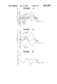
- FIG. 10 shows the cogging torque characteristic of a motor having ten magnetic poles and fifteen salient poles.
- ⁇ refers to an angle formed at the end portion of each of the outer cores 12 in the magnetizing device 10 in the same manner as in FIG. 2.
- the phase of the cogging torque is changed by changing ⁇ as in FIG. 3.
- the absolute value of the cogging torque having the period as above-mentioned is sometimes smaller than the cogging torque having a period of 2 ⁇ 'i which is produced due to scattering of the strength of the magnetization of the N poles and the S poles. Accordingly, sometimes, it is difficult to determine the period of the cogging torque of the present invention in view of the cogging torque characteristics.
- the basic period ⁇ 'i of the cogging torque is 12°
- the absolute value of the cogging torque having the above-mentioned period is extremely small due to increase in number of the magnetic poles and the salient poles of the motor, and it is smaller than the cogging torque produced due to scattering of the strength of the magnetization of the N poles and the S poles.
- the cogging torque of ⁇ 'i is found on the cogging torque of the period of 2 ⁇ 'i.
- FIGS. 11 and 12 are respectively power spectrum diagrams obtained by frequency analysis of the cogging torque at the revolution angles ⁇ of 28° and 26° in FIG. 10.
- the strength of the spectrum b is about 12 times as much as the strength of the spectrum d. Accordingly, the spectrum a shows the greatest value.
- the fact that the strength of the spectrum b is greater than the spectrum d mainly owes to high frequency components produced when the cogging torque pattern having the period of 2 ⁇ 'i is deviated from a sine wave.
- the cogging torque can be judged by a power spectrum.
- the strength of the spectrum b corresponding to the basic period ⁇ 'i of the cogging torque is about 30 times or smaller than the strength of the spectrum d corresponding to the period ⁇ i of the cogging torque of the present invention
- the magnetic poles having the value of magnetization can be used for a motor which minimizes the cogging torque.
- the magnetization angle and the magnetization pattern can be precisely controlled by changing the power spectrum.
- the phase of the cogging torque having the period of ⁇ 'i is detected and at the same time, the cogging torque having the period of ⁇ 'i is reduced, with the result of obtaining the cogging torque having the period of ⁇ 'i as a torque pattern.
Landscapes
- Engineering & Computer Science (AREA)
- Power Engineering (AREA)
- Permanent Magnet Type Synchronous Machine (AREA)
- Permanent Field Magnets Of Synchronous Machinery (AREA)
- Brushless Motors (AREA)
Abstract
Description
Claims (10)
Applications Claiming Priority (2)
| Application Number | Priority Date | Filing Date | Title |
|---|---|---|---|
| JP60-90980 | 1985-04-30 | ||
| JP60090980A JPH0789728B2 (en) | 1985-04-30 | 1985-04-30 | Motor |
Related Parent Applications (1)
| Application Number | Title | Priority Date | Filing Date |
|---|---|---|---|
| US06856354 Continuation | 1986-04-28 |
Publications (1)
| Publication Number | Publication Date |
|---|---|
| US4812692A true US4812692A (en) | 1989-03-14 |
Family
ID=14013664
Family Applications (1)
| Application Number | Title | Priority Date | Filing Date |
|---|---|---|---|
| US07/149,923 Expired - Fee Related US4812692A (en) | 1985-04-30 | 1988-01-29 | Motor |
Country Status (5)
| Country | Link |
|---|---|
| US (1) | US4812692A (en) |
| EP (1) | EP0201793B1 (en) |
| JP (1) | JPH0789728B2 (en) |
| KR (1) | KR940000524B1 (en) |
| DE (1) | DE3683864D1 (en) |
Cited By (15)
| Publication number | Priority date | Publication date | Assignee | Title |
|---|---|---|---|---|
| US5028073A (en) * | 1990-01-08 | 1991-07-02 | General Electric Company | Dynamic vehicle suspension system including electronically commutated motor |
| US5204569A (en) * | 1990-02-07 | 1993-04-20 | Asmo Co., Ltd. | Anisotropic magnet for rotary electric machine |
| US5220228A (en) * | 1990-02-16 | 1993-06-15 | Sankyo Seiki Mfg. Co., Ltd. | Rotating electric machine with bevelled armature poles |
| US5341057A (en) * | 1992-10-14 | 1994-08-23 | Tokyo Parts Industrial Co., Ltd. | Vibrator motor for a wireless silent alerting device |
| US5399311A (en) * | 1991-11-15 | 1995-03-21 | Daido Tokushuko Kabushiki Kaisha | Radial anisotropic ring magnet with a sinusoidal waveform and producing method thereof |
| US5923110A (en) * | 1997-03-17 | 1999-07-13 | Industrial Technology Research Institute | Spindle motor for optical disc drives |
| US20030080641A1 (en) * | 2001-10-29 | 2003-05-01 | Susumu Ando | Permanent magnet type rotary electric device |
| US20030202893A1 (en) * | 2002-04-30 | 2003-10-30 | Denso Corporation | Fuel pump for high torque in compact structure |
| US20040084985A1 (en) * | 2002-08-08 | 2004-05-06 | Takao Hasumi | Brushless motor |
| US20050023917A1 (en) * | 2001-12-21 | 2005-02-03 | Bsh Bosch Und Siemens Hausgerate Gmbh | Electric motor and method for producing the motor |
| US20080111436A1 (en) * | 2002-10-01 | 2008-05-15 | Isamu Takehara | Permanent magnet for a motor, motor, and magnetizing method |
| US20100238591A1 (en) * | 2009-03-19 | 2010-09-23 | Alphana Technology Co., Ltd. | Disk drive device rotationally driving recording disk |
| US20110006865A1 (en) * | 2009-07-09 | 2011-01-13 | General Electric Company | In-situ magnetizer |
| US20110012463A1 (en) * | 2007-08-01 | 2011-01-20 | Gerald David Duncan | appliance, rotor and magnet element |
| US20150340913A1 (en) * | 2014-05-22 | 2015-11-26 | Delta Electronics, Inc. | Low-cog permanent magnet motor |
Families Citing this family (2)
| Publication number | Priority date | Publication date | Assignee | Title |
|---|---|---|---|---|
| EP0409661B1 (en) * | 1989-07-21 | 1995-01-11 | Mitsubishi Chemical Corporation | Motor |
| FR2733859B1 (en) * | 1995-05-04 | 1997-08-14 | Oudet Claude | ECONOMICAL STEP OR SYNCHRONOUS MOTOR |
Citations (5)
| Publication number | Priority date | Publication date | Assignee | Title |
|---|---|---|---|---|
| US3860843A (en) * | 1970-06-26 | 1975-01-14 | Matsushita Electric Ind Co Ltd | Rotating electric machine with reduced cogging |
| US4074157A (en) * | 1976-10-04 | 1978-02-14 | Synchro-Start Products, Inc. | Permanent magnet A.C. signal generator |
| US4280072A (en) * | 1977-05-26 | 1981-07-21 | Matsushita Electric Industrial Co., Ltd. | Rotating electric machine |
| US4575652A (en) * | 1984-09-27 | 1986-03-11 | Synektron Corporation | Permanent magnet motor having high starting torque and narrowly-defined detent zones |
| US4713569A (en) * | 1986-06-20 | 1987-12-15 | 501 Aeroflex Laboratories, Incorporated | Low cogging motor |
Family Cites Families (3)
| Publication number | Priority date | Publication date | Assignee | Title |
|---|---|---|---|---|
| CA934814A (en) * | 1970-06-26 | 1973-10-02 | Kawasaki Itaru | Rotating electric machine |
| JPS5444707A (en) * | 1977-09-14 | 1979-04-09 | Sony Corp | Dc brushless motor |
| US4354668A (en) * | 1981-08-20 | 1982-10-19 | Jones & Laughlin Steel Incorporated | Method and apparatus for determining completion of a cast in blast furnace casthouse pollution suppression system |
-
1985
- 1985-04-30 JP JP60090980A patent/JPH0789728B2/en not_active Expired - Lifetime
-
1986
- 1986-04-28 DE DE8686105836T patent/DE3683864D1/en not_active Expired - Fee Related
- 1986-04-28 EP EP86105836A patent/EP0201793B1/en not_active Expired - Lifetime
- 1986-04-29 KR KR1019860003318A patent/KR940000524B1/en active IP Right Grant
-
1988
- 1988-01-29 US US07/149,923 patent/US4812692A/en not_active Expired - Fee Related
Patent Citations (5)
| Publication number | Priority date | Publication date | Assignee | Title |
|---|---|---|---|---|
| US3860843A (en) * | 1970-06-26 | 1975-01-14 | Matsushita Electric Ind Co Ltd | Rotating electric machine with reduced cogging |
| US4074157A (en) * | 1976-10-04 | 1978-02-14 | Synchro-Start Products, Inc. | Permanent magnet A.C. signal generator |
| US4280072A (en) * | 1977-05-26 | 1981-07-21 | Matsushita Electric Industrial Co., Ltd. | Rotating electric machine |
| US4575652A (en) * | 1984-09-27 | 1986-03-11 | Synektron Corporation | Permanent magnet motor having high starting torque and narrowly-defined detent zones |
| US4713569A (en) * | 1986-06-20 | 1987-12-15 | 501 Aeroflex Laboratories, Incorporated | Low cogging motor |
Cited By (22)
| Publication number | Priority date | Publication date | Assignee | Title |
|---|---|---|---|---|
| US5028073A (en) * | 1990-01-08 | 1991-07-02 | General Electric Company | Dynamic vehicle suspension system including electronically commutated motor |
| US5204569A (en) * | 1990-02-07 | 1993-04-20 | Asmo Co., Ltd. | Anisotropic magnet for rotary electric machine |
| US5220228A (en) * | 1990-02-16 | 1993-06-15 | Sankyo Seiki Mfg. Co., Ltd. | Rotating electric machine with bevelled armature poles |
| US5399311A (en) * | 1991-11-15 | 1995-03-21 | Daido Tokushuko Kabushiki Kaisha | Radial anisotropic ring magnet with a sinusoidal waveform and producing method thereof |
| US5341057A (en) * | 1992-10-14 | 1994-08-23 | Tokyo Parts Industrial Co., Ltd. | Vibrator motor for a wireless silent alerting device |
| US5923110A (en) * | 1997-03-17 | 1999-07-13 | Industrial Technology Research Institute | Spindle motor for optical disc drives |
| US6836044B2 (en) * | 2001-10-29 | 2004-12-28 | Kabushiki Kaisha Moric | Permanent magnet type rotary electric device |
| US20030080641A1 (en) * | 2001-10-29 | 2003-05-01 | Susumu Ando | Permanent magnet type rotary electric device |
| EP1306963A1 (en) * | 2001-10-29 | 2003-05-02 | Kabushiki Kaisha Moric | Permanent magnet type rotary electric device |
| US20050023917A1 (en) * | 2001-12-21 | 2005-02-03 | Bsh Bosch Und Siemens Hausgerate Gmbh | Electric motor and method for producing the motor |
| US7157828B2 (en) * | 2002-04-30 | 2007-01-02 | Denso Corporation | Fuel pump for high torque in compact structure |
| US20030202893A1 (en) * | 2002-04-30 | 2003-10-30 | Denso Corporation | Fuel pump for high torque in compact structure |
| US20040084985A1 (en) * | 2002-08-08 | 2004-05-06 | Takao Hasumi | Brushless motor |
| US6972503B2 (en) * | 2002-08-08 | 2005-12-06 | Daido Tokushuko Kabushiki Kaisha | Brushless motor |
| US20080111436A1 (en) * | 2002-10-01 | 2008-05-15 | Isamu Takehara | Permanent magnet for a motor, motor, and magnetizing method |
| US20110012463A1 (en) * | 2007-08-01 | 2011-01-20 | Gerald David Duncan | appliance, rotor and magnet element |
| US9509184B2 (en) | 2007-08-01 | 2016-11-29 | Fisher & Paykel Appliances Limited | Appliance, rotor and magnet element |
| US20100238591A1 (en) * | 2009-03-19 | 2010-09-23 | Alphana Technology Co., Ltd. | Disk drive device rotationally driving recording disk |
| US8368282B2 (en) * | 2009-03-19 | 2013-02-05 | Alphana Technology Co., Ltd. | Disk drive device rotationally driving recording disk |
| US20110006865A1 (en) * | 2009-07-09 | 2011-01-13 | General Electric Company | In-situ magnetizer |
| US8766753B2 (en) * | 2009-07-09 | 2014-07-01 | General Electric Company | In-situ magnetizer |
| US20150340913A1 (en) * | 2014-05-22 | 2015-11-26 | Delta Electronics, Inc. | Low-cog permanent magnet motor |
Also Published As
| Publication number | Publication date |
|---|---|
| KR860008636A (en) | 1986-11-17 |
| EP0201793A2 (en) | 1986-11-20 |
| EP0201793B1 (en) | 1992-02-12 |
| EP0201793A3 (en) | 1988-04-27 |
| JPH0789728B2 (en) | 1995-09-27 |
| KR940000524B1 (en) | 1994-01-21 |
| JPS61254054A (en) | 1986-11-11 |
| DE3683864D1 (en) | 1992-03-26 |
Similar Documents
| Publication | Publication Date | Title |
|---|---|---|
| US4812692A (en) | Motor | |
| US7342338B2 (en) | Permanent magnet electric motor with reduced cogging torque | |
| US4748359A (en) | Permanent magnet rotor with sinusoidal flux pattern | |
| US6313558B1 (en) | Electric rotary machine having concentrated winding stator | |
| US4642502A (en) | Dynamoelectric machine with permanent magnet and magnet mounting surface arrangement | |
| US4445061A (en) | Wide air gap permanent magnet motors | |
| US6181035B1 (en) | Permanent magnet electric motor having reduced cogging torque | |
| US7408279B2 (en) | Permanent magnet synchronous motor including permanent magnet with tapered outer edges | |
| US4998032A (en) | Permanent magnet excited electric motor | |
| US5204569A (en) | Anisotropic magnet for rotary electric machine | |
| US7902707B2 (en) | Anisotropic permanent magnet motor | |
| US4700097A (en) | Synchronous machine | |
| US6218760B1 (en) | Brushless motor | |
| US5973432A (en) | Motor having magnetic slot closure for salient poles | |
| US20020180295A1 (en) | Dynamo electric machine with permanent magnet type rotor | |
| EP0193611A1 (en) | Permanent magnet field system synchronous motor | |
| EP1014541A1 (en) | Permanent magnet synchronous motor | |
| US6882080B2 (en) | Permanent magnet synchronous motor | |
| US20060238038A1 (en) | Grooved part of an electric motor | |
| JP2587608B2 (en) | Motor | |
| JPH01234038A (en) | Revolving-field type synchronous machine | |
| US5777415A (en) | Two-phase unipolar drive type brushless DC motor | |
| EP0542521B1 (en) | Method of making a radial anisotropic ring magnet | |
| USRE32654E (en) | Wide air gap permanent magnet motors | |
| JP2598770Y2 (en) | Rotating electric machine |
Legal Events
| Date | Code | Title | Description |
|---|---|---|---|
| AS | Assignment |
Owner name: MITSUBISHI CHEMICAL INDUSTRIES LIMITED, 5-2, MARUN Free format text: ASSIGNMENT OF ASSIGNORS INTEREST.;ASSIGNOR:ARITA, YOJI;REEL/FRAME:004918/0501 Effective date: 19860421 Owner name: MITSUBISHI STEEL MFG CO., LTD., 6-2, OHTEMACHI 2-C Free format text: ASSIGNMENT OF ASSIGNORS INTEREST.;ASSIGNOR:ARITA, YOJI;REEL/FRAME:004918/0501 Effective date: 19860421 |
|
| AS | Assignment |
Owner name: MITSUBISHI KASEI CORPORATION Free format text: CHANGE OF NAME;ASSIGNOR:MITSUBISHI CHEMICAL INDUSTRIES LIMITED;REEL/FRAME:005004/0736 Effective date: 19880601 Owner name: MITSUBISHI KASEI CORPORATION, JAPAN Free format text: CHANGE OF NAME;ASSIGNOR:MITSUBISHI CHEMICAL INDUSTRIES LIMITED;REEL/FRAME:005004/0736 Effective date: 19880601 |
|
| FEPP | Fee payment procedure |
Free format text: PAYOR NUMBER ASSIGNED (ORIGINAL EVENT CODE: ASPN); ENTITY STATUS OF PATENT OWNER: LARGE ENTITY |
|
| REMI | Maintenance fee reminder mailed | ||
| LAPS | Lapse for failure to pay maintenance fees | ||
| FP | Lapsed due to failure to pay maintenance fee |
Effective date: 19930314 |
|
| STCH | Information on status: patent discontinuation |
Free format text: PATENT EXPIRED DUE TO NONPAYMENT OF MAINTENANCE FEES UNDER 37 CFR 1.362 |