US4804331A - Device for installing printed circuit board - Google Patents
Device for installing printed circuit board Download PDFInfo
- Publication number
- US4804331A US4804331A US07/134,976 US13497687A US4804331A US 4804331 A US4804331 A US 4804331A US 13497687 A US13497687 A US 13497687A US 4804331 A US4804331 A US 4804331A
- Authority
- US
- United States
- Prior art keywords
- printed circuit
- circuit board
- members
- movable
- flexible printed
- Prior art date
- Legal status (The legal status is an assumption and is not a legal conclusion. Google has not performed a legal analysis and makes no representation as to the accuracy of the status listed.)
- Expired - Lifetime
Links
Images


Classifications
-
- H—ELECTRICITY
- H05—ELECTRIC TECHNIQUES NOT OTHERWISE PROVIDED FOR
- H05K—PRINTED CIRCUITS; CASINGS OR CONSTRUCTIONAL DETAILS OF ELECTRIC APPARATUS; MANUFACTURE OF ASSEMBLAGES OF ELECTRICAL COMPONENTS
- H05K1/00—Printed circuits
- H05K1/02—Details
- H05K1/0277—Bendability or stretchability details
- H05K1/028—Bending or folding regions of flexible printed circuits
-
- H—ELECTRICITY
- H01—ELECTRIC ELEMENTS
- H01R—ELECTRICALLY-CONDUCTIVE CONNECTIONS; STRUCTURAL ASSOCIATIONS OF A PLURALITY OF MUTUALLY-INSULATED ELECTRICAL CONNECTING ELEMENTS; COUPLING DEVICES; CURRENT COLLECTORS
- H01R35/00—Flexible or turnable line connectors, i.e. the rotation angle being limited
- H01R35/02—Flexible line connectors without frictional contact members
-
- H—ELECTRICITY
- H02—GENERATION; CONVERSION OR DISTRIBUTION OF ELECTRIC POWER
- H02G—INSTALLATION OF ELECTRIC CABLES OR LINES, OR OF COMBINED OPTICAL AND ELECTRIC CABLES OR LINES
- H02G11/00—Arrangements of electric cables or lines between relatively-movable parts
-
- H—ELECTRICITY
- H05—ELECTRIC TECHNIQUES NOT OTHERWISE PROVIDED FOR
- H05K—PRINTED CIRCUITS; CASINGS OR CONSTRUCTIONAL DETAILS OF ELECTRIC APPARATUS; MANUFACTURE OF ASSEMBLAGES OF ELECTRICAL COMPONENTS
- H05K2201/00—Indexing scheme relating to printed circuits covered by H05K1/00
- H05K2201/05—Flexible printed circuits [FPCs]
- H05K2201/055—Folded back on itself
Definitions
- This invention relates to flexible printed circuit boards for use in electrical connection between two members movable relative to each other and, more particularly, to a method for installing the same.
- the flexible printed circuit board is so thin and so sufficient in flexibility as to bend itself to any desired strong curvature and to be installed in a narrow space of the interior of the instrument with good mobility of the bent portion thereof. Hence, it has found its use in cameras at their housing and lens barrels, and other compact instruments.
- FIGS. 1 through 3(B) there is shown an expanded type of the one of the above-described concepts which has the central U-turn in the flexible printed circuit board. That is, when to install the printed circuit board in the lens barrel, the space it occupies is, as shown in FIGS. 1 and 2, often taken between a fixed tube 61 whose one end is coupled with the camera body and a movable sleeve 62 for focusing or zooming.
- the flexible printed circuit board 63 is installed in such a manner as to permit formation of two letter U-shaped bent portions 64 and 65 as shown in FIG. 2. And, these bent portions 64 and 65 are arranged to change their axial positions in accompaniment with movement of the sleeve 62.
- one of the bent portions, in this instance, 64 is caused to come into contact with the substrate of the board 63.
- the frictionally contacting areas of the upper surface of the bent portion 64 and the lower surface of the board 63 eventually worn out with a damage of the cover layer.
- the bent portions 64 and 65 were hindered from smoothly changing their positions. Again, if such a stress was suddenly released, the board 63 would take an abnormal form. Thus, there was a high possibility of damaging the electrical fidelity of the printed circuit board.
- the diameter of the movable sleeve 62 tended to increase.
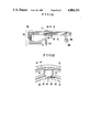
- a stripe-shaped flexible printed circuit board 53 is set up in such a way as to form a bent portion 54 of letter "U" shape.
- the movable sleeve 52 is provided with an axial shallow groove 55 of flat bottom.
- the bent portion 54 can sweep along the groove 55 without causing its side edges to be pressed against the otherwise curved inner surface of the sleeve 52. Hence, no unduly large stress is applied to the circuit pattern of the board 53 at the center of the width thereof. Thus, the board can change in position without damaging the electrical fidelity.
- An object of the present invention is to provide a device for installing a flexible printed circuit board for electrical connection between two members movable relative to each other in such a manner that the flexible printed circuit board can smoothly change its position while still preserving high electrical fidelity.
- FIG. 1 is a perspective view of the lens barrel with a portion broken away to illustrate the conventional method of installation of the printed circuit board.
- FIG. 2 is a sectional view of the main parts of FIG. 1.
- FIGS. 3(A) and 3(B) are diagrams taken to explain the problem of FIG. 1.
- FIG. 4 is a perspective view of the lens barrel with a portion broken away to illustrate another example of the conventional installation of the printed circuit board.
- FIG. 5 is a longitudinal section view of a first embodiment of the invention applied to part of the lens barrel.
- FIG. 6(A) is an expanded view of the printed circuit board of the invention.
- FIG. 6(B) is an expanded view of the conventional printed circuit board.
- FIG. 7 is a perspective view illustrating a method of installing the printed circuit board according to the first embodiment of the invention.
- FIG. 8 is a partly side elevational sectional view of a second embodiment of the invention.
- FIG. 9 is a perspective view of the installation of the printed circuit board of FIG. 8.
- FIG. 10(A) is a perspective view of a third embodiment of the invention applied to part of the lens barrel.
- FIGS. 10(B) and 10(C) are perspective views illustrating change of the position of the printed circuit board of FIG. 10(A).
- FIG. 11 is an expanded view of the printed circuit board of FIG. 10(A).
- FIG. 12 is a fragmentary front view of the lens barrel with the bent portion of the board of FIG. 10(A) in detail.
- FIG. 13 is a sectional view of the lens barrel of FIG. 10(A).
- FIG. 5 there is shown the first embodiment of the invention applied to the lens barrel.
- the lens barrel comprises a fixed tube 1 as the first member and a movable sleeve 2 as the second member.
- a movable lens system 20 for zooming is held in the inner diameter of the sleeve 2.
- the fixed tube 1 has a mount 4 at the rear end on which a main printed circuit board 5 is positioned.
- An actuator (electric motor) 6 for driving a diaphragm is fixedly carried on the movable sleeve 2.
- the main board 5 and the actuator 6 are electrically connected to each other by a flexible printed circuit board 3.
- the flexible printed circuit board 3 is made up from, for example, a double-width stripe of printed circuit board shown in FIG. 6(A).
- a longitudinal cutout portion 31 of direction almost parallel to the direction of movement of the movable sleeve 2 two parts, or a first side piece 3a and a second side piece 3b, are formed.
- one side piece 3a is bent 180° from the neighborhood of a dashed line 32 to a form shown in FIG. 7.
- 33 denotes a bent portion of letter "U" shape.
- a free end 34 of the first side piece 3a is provided with lead patches 34a (exposed portions for electrical interconnection of electrically conductive patterns) to be coupled to the actuator 6.
- a free end 35 of the second side piece 3b is provided with lead patches 35a (exposed portions for electrical interconnection of the electrically conductive patterns) to be coupled to the main printed circuit board 5.
- the printed circuit board 3 of the form shown in FIG. 7, when installed within the lens barrel of FIG. 5, has its one set of lead patches 34a electrically connected to the actuator 6 mounted on the movable sleeve 2 and its opposite set of lead patches 35a electrically connected to the main printed circuit board 5, wherein the bent portion 33 falls within the space between the end portions 34 and 35.
- the embodiment of the invention has a feature that a greater number of items can be taken out of a sheet of substrate of certain size, leaving smaller least material waste than when the board is constructed in a merely one-directionally extended form shown in FIG. 6(B) as in the prior art.
- this embodiment may be modified so that instead of making erect the end portions 34 and 35, they extend in the same plane as that of the side pieces 3a and 3b.
- FIGS. 8 and 9 show another embodiment of the invention where the flexible printed circuit board 3 is constructed in a different form from that shown in FIGS. 5 and 7, and the same reference numerals have been employed to denote the similar parts to those shown in the latter.
- the erected end portions of the two side pieces 3a and 3b of the printed circuit board 3 direct to opposite direction to each other, as the movable sleeve 2 is positioned outside the fixed tube 1.
- a set of lead patches 34a on the front end portion 34 are connected to an electric motor 7 on the outer surface of the movable sleeve 2, and a set of lead patches 35a of the rear end portion 35 are connected to the main printed circuit board 5 positioned inside the fixed tube 1.
- the motor 7 is used to drive a focusing ring 8 holding a focusing lens system 80 through a gear 9.
- a pin 10 restrains the movable sleeve 2 from rotation relative to the fixed tube 1.
- the flexible printed circuit board is shown as oriented with its length to the longitude (axial direction) of the lens barrel, the present invention can be applied even to the case where the length of the flexible printed circuit board extends along the circumference of the lens barrel to effect an equivalent result.
- the use of such forms as described above in constructing the flexible printed circuit board provides a possibility of designing the first and second members movable relative to each other as constituting part of the lens barrel in such a way that the space the electrical connection between these members occupies is shorter in height and better in manufacturability than was heretofore possible. Further, it permits smooth variation of the position of the printed circuit board to occur, since the movement of the movable member never gives an unduly large stress to it. Thus, an installation of the printed circuit board which enables the high electrical fidelity to be preserved and the size of the instrument employing the same to be minimized can be achieved.
- FIG. 10(A) is a schematic perspective view of the third embodiment of the invention applied to the lens barrel
- FIG. 12 is a fragmentary cross-sectional view of the lens barrel of FIG. 10(A)
- FIG. 13 is a longitudinal section view of the lens barrel of FIG. 10(A).
- a fixed tube 101 as the first member is fixedly secured to a second fixed tube 102 having a coupling mount 141.
- a movable sleeve 105 as the second member fixedly carries a lens system is fitted on the outer diameter of the fixed tube 101, and is axially movable by a longitudinal key slot 101e and a key 105a in engagement.
- the printed circuit board 103 is a flexible printed circuit board of, for example, band form whose expanded view is shown in FIG. 11. In actual practice, it takes the form shown in FIGS. 10(B) and 10(C).
- the printed circuit board 103 is bent 180° at the neighborhood of a position indicated by a dashed line 131 shown in FIG. 11 to form a turned portion 103a of letter "U" shape and its fixing portion 103c is inserted into a space formed between the movable sleeve 105 serving as the outer barrel and the fixed tube 101 serving as the inner barrel.
- Ends 103b and 103b' of the printed circuit board 103 are electrically connected to an AF actuator 148 and another printed circuit board 106 on the movable sleeve 105, respectively, and the other end 103d is electrically connected to yet another printed circuit board (not shown) on the second fixed tube 102.
- the turned portion 103a of the printed circuit board 103 takes a position shown in FIG. 10(B) when the movable sleeve 105 is in the terminal end of forward movement, or another position 103a' shown in FIG. 10(C) when in the end of rearward movement.
- the printed circuit board 103 is fastened to the fixed tube 101 at the fixing portion 103c.
- the board of FIG. 11 is first folded in intimate contact in the circumferential direction and then fixedly secured to the fixed tube 101 on a flat plane portion 101a thereof by a screw fastener.
- curvature R To prevent breaking of wire at the folded edge, some curvature R must be retained. This results in formation of a club at the fixing portion 103c. As an escape for the club, the flat plane portion 101a of an external axial groove is made recess by one step at a portion 101b beneath the club.
- the recessed portion 101b takes its place sideward from the center of the width of the groove 101a, though the bottom of the groove is dug by one step, the thickness of the fixed tube 101 is never largely decreased, as will be seen from FIG. 12.
- an actuator 142 for the diaphragm is fixedly carried on a holder tube 114a for holding the third lens unit 144 which moves at exactly or nearly the same speed as that of movement of the first lens unit 143, and is electrically connected to the flexible printed circuit board 103 through another printed circuit board 106.
- the printed circuit board 106 passes through the longitudinal key slot 101e of the fixed tube 101 and a hole portion 105b of the movable sleeve 105 and projects radially outwardly of the movable sleeve 105, thus reaching the printed circuit board 103.
- the longitudinal key slot 101e is utilized as the hole for passing the printed circuit board 106 across the wall of the fixed tube 101 to save the addition of another hole, if there is room for creation of a space therefor, another long slot to be solely used for the printed circuit board 106 may be provided.
- the lens barrel further includes a manual focusing ring 145, a helicoid threaded member 146, an outer or decoration barrel 147, an AF actuator 148 and a holder tube 149a for holding the second lens unit 149.
- arrangement is such that as the movable sleeve 105 moves axially, the turned portion 103a of the printed circuit board 103 axially displaces itself.
- both side edges of the upper root of the turned portion 103a of the printed circuit board 103 are subjected to frictional sideway movement on the inner surface 121 of the second fixed tube 102, as the turned portion 103a moves. It is, therefore, another feature of this embodiment that portions 133 of the printed circuit board 103 whose edges come into contact with the innersurface 121 of the second fixed tube 102 when it is turned, is widened in the circumference direction as compared with other portions.
- connection patterns are formed in both widened portions 133.
- this embodiment has achieved realization of the electrical connection with high fidelity.
- the use of the invention provides a possibility of installing the printed circuit board in the instrument of reduced size with improved manufacturability and electrically high fidelity.
Landscapes
- Engineering & Computer Science (AREA)
- Microelectronics & Electronic Packaging (AREA)
- Lens Barrels (AREA)
Abstract
Description
Claims (9)
Applications Claiming Priority (4)
| Application Number | Priority Date | Filing Date | Title |
|---|---|---|---|
| JP61-200443[U] | 1986-12-27 | ||
| JP61-200442[U] | 1986-12-27 | ||
| JP1986200443U JPH0436154Y2 (en) | 1986-12-27 | 1986-12-27 | |
| JP20044286U JPH0648934Y2 (en) | 1986-12-27 | 1986-12-27 | Printed board mounting device |
Publications (1)
| Publication Number | Publication Date |
|---|---|
| US4804331A true US4804331A (en) | 1989-02-14 |
Family
ID=26512193
Family Applications (1)
| Application Number | Title | Priority Date | Filing Date |
|---|---|---|---|
| US07/134,976 Expired - Lifetime US4804331A (en) | 1986-12-27 | 1987-12-18 | Device for installing printed circuit board |
Country Status (1)
| Country | Link |
|---|---|
| US (1) | US4804331A (en) |
Cited By (13)
| Publication number | Priority date | Publication date | Assignee | Title |
|---|---|---|---|---|
| US4921432A (en) * | 1988-10-14 | 1990-05-01 | Space Industries Partnership, L.P. | Wire conducting rotary coupling employing protective skirt |
| US4964697A (en) * | 1987-11-27 | 1990-10-23 | Canon Kabushiki Kaishi | Lens barrel having circuit board with polygonal aperture |
| US4990948A (en) * | 1986-12-27 | 1991-02-05 | Canon Kabushiki Kaisha | Flexible printed circuit board |
| US4999656A (en) * | 1988-05-24 | 1991-03-12 | Canon Kabushiki Kaisha | Interchangeable lens with double-sided printed circuit board |
| FR2678984A1 (en) * | 1991-07-12 | 1993-01-15 | Seram | Device for conducting signals between a piston with reciprocating movement of high frequency, and a fixed member |
| US5231449A (en) * | 1988-06-03 | 1993-07-27 | Asahi Kogaku Kogyo Kabushiki Kaisha | Zoom lens barrel and camera incorporating such barrel |
| US5270868A (en) * | 1988-06-03 | 1993-12-14 | Asahi Kogaku Kogyo Kabushiki Kaisha | Zoom lens barrel and camera incorporating such barrel |
| US5371569A (en) * | 1992-06-23 | 1994-12-06 | Asahi Kogaku Kogyo Kabushiki Kaisha | Mounting apparatus of flexible printed circuit board |
| US5717969A (en) * | 1993-10-21 | 1998-02-10 | Nikon Corporation | Lens barrel with flexible printed circuit boards |
| US20120314312A1 (en) * | 2010-02-26 | 2012-12-13 | Yoshifumi Mitani | Lens barrel |
| US20140355138A1 (en) * | 2013-05-31 | 2014-12-04 | Sony Corporation | Lens barrel and imaging apparatus |
| TWI682209B (en) * | 2016-04-13 | 2020-01-11 | 台灣東電化股份有限公司 | Camera lens module |
| US10684442B2 (en) | 2016-04-13 | 2020-06-16 | Tdk Taiwan Corp. | Camera lens module |
-
1987
- 1987-12-18 US US07/134,976 patent/US4804331A/en not_active Expired - Lifetime
Cited By (15)
| Publication number | Priority date | Publication date | Assignee | Title |
|---|---|---|---|---|
| US4990948A (en) * | 1986-12-27 | 1991-02-05 | Canon Kabushiki Kaisha | Flexible printed circuit board |
| US4964697A (en) * | 1987-11-27 | 1990-10-23 | Canon Kabushiki Kaishi | Lens barrel having circuit board with polygonal aperture |
| US4999656A (en) * | 1988-05-24 | 1991-03-12 | Canon Kabushiki Kaisha | Interchangeable lens with double-sided printed circuit board |
| US5270868A (en) * | 1988-06-03 | 1993-12-14 | Asahi Kogaku Kogyo Kabushiki Kaisha | Zoom lens barrel and camera incorporating such barrel |
| US5231449A (en) * | 1988-06-03 | 1993-07-27 | Asahi Kogaku Kogyo Kabushiki Kaisha | Zoom lens barrel and camera incorporating such barrel |
| AU650384B2 (en) * | 1988-06-03 | 1994-06-16 | Asahi Kogaku Kogyo Kabushiki Kaisha | Zoom lens barrel and camera incorporating such barrel |
| US4921432A (en) * | 1988-10-14 | 1990-05-01 | Space Industries Partnership, L.P. | Wire conducting rotary coupling employing protective skirt |
| FR2678984A1 (en) * | 1991-07-12 | 1993-01-15 | Seram | Device for conducting signals between a piston with reciprocating movement of high frequency, and a fixed member |
| US5371569A (en) * | 1992-06-23 | 1994-12-06 | Asahi Kogaku Kogyo Kabushiki Kaisha | Mounting apparatus of flexible printed circuit board |
| US5717969A (en) * | 1993-10-21 | 1998-02-10 | Nikon Corporation | Lens barrel with flexible printed circuit boards |
| US20120314312A1 (en) * | 2010-02-26 | 2012-12-13 | Yoshifumi Mitani | Lens barrel |
| US8605373B2 (en) * | 2010-02-26 | 2013-12-10 | Konica Minolta Advanced Layers, Inc. | Lens barrel |
| US20140355138A1 (en) * | 2013-05-31 | 2014-12-04 | Sony Corporation | Lens barrel and imaging apparatus |
| TWI682209B (en) * | 2016-04-13 | 2020-01-11 | 台灣東電化股份有限公司 | Camera lens module |
| US10684442B2 (en) | 2016-04-13 | 2020-06-16 | Tdk Taiwan Corp. | Camera lens module |
Similar Documents
| Publication | Publication Date | Title |
|---|---|---|
| US4804331A (en) | Device for installing printed circuit board | |
| EP0609913B1 (en) | Flexible printed circuit board for a camera | |
| US4864348A (en) | Structure for installing flexible printed circuit board | |
| US5267088A (en) | Code plate mounting device | |
| US4457609A (en) | Device for coupling a lens barrel and a camera body | |
| US6014269A (en) | Engaging structure of relatively-rotatable cylindrical members | |
| US4514039A (en) | Lens mounting | |
| US7625141B2 (en) | Lens barrel including a flexible printed wiring board | |
| US5446593A (en) | Lens advancing mechanism | |
| US5712734A (en) | Zoom lens barrel for moving lenses in the optical axis direction without increasing the length of the zoom lens barrel | |
| JP2003131105A (en) | Camera | |
| US6690581B2 (en) | Connection structure of flexible board arranged in camera | |
| EP0392511B1 (en) | Lens barrel | |
| JPH0648934Y2 (en) | Printed board mounting device | |
| JP2691922B2 (en) | Position detection device | |
| US4730901A (en) | Lens barrel with internal motor focusing | |
| JPH05127242A (en) | Intermediate barrel and camera system | |
| JP2001013397A (en) | Focal distance detecting mechanism for zoom lens camera | |
| JPH07151948A (en) | Lens barrel | |
| JPH0436154Y2 (en) | ||
| JPH0727097B2 (en) | Lens barrel | |
| JP3976873B2 (en) | Lens barrel | |
| US4824207A (en) | Lens barrel | |
| JP2800325B2 (en) | camera | |
| JPH0637370Y2 (en) | Lens barrel with built-in printed circuit board |
Legal Events
| Date | Code | Title | Description |
|---|---|---|---|
| AS | Assignment |
Owner name: CANON KABUSHIKI KAISHA, 3-30-2, SHIMOMARUKO, OHTA- Free format text: ASSIGNMENT OF ASSIGNORS INTEREST.;ASSIGNORS:EGUCHI, MASAHARU;FUJIWARA, YUTAKA;YAMANOUCHI, HARUHIKO;AND OTHERS;REEL/FRAME:004806/0208 Effective date: 19871215 Owner name: CANON KABUSHIKI KAISHA, 3-30-2, SHIMOMARUKO, OHTA- Free format text: ASSIGNMENT OF ASSIGNORS INTEREST;ASSIGNORS:EGUCHI, MASAHARU;FUJIWARA, YUTAKA;YAMANOUCHI, HARUHIKO;AND OTHERS;REEL/FRAME:004806/0208 Effective date: 19871215 |
|
| STCF | Information on status: patent grant |
Free format text: PATENTED CASE |
|
| FPAY | Fee payment |
Year of fee payment: 4 |
|
| FPAY | Fee payment |
Year of fee payment: 8 |
|
| FEPP | Fee payment procedure |
Free format text: PAYOR NUMBER ASSIGNED (ORIGINAL EVENT CODE: ASPN); ENTITY STATUS OF PATENT OWNER: LARGE ENTITY |
|
| FEPP | Fee payment procedure |
Free format text: PAYER NUMBER DE-ASSIGNED (ORIGINAL EVENT CODE: RMPN); ENTITY STATUS OF PATENT OWNER: LARGE ENTITY |
|
| FPAY | Fee payment |
Year of fee payment: 12 |