US4768700A - Diffusion bonding method - Google Patents
Diffusion bonding method Download PDFInfo
- Publication number
- US4768700A US4768700A US07/086,940 US8694087A US4768700A US 4768700 A US4768700 A US 4768700A US 8694087 A US8694087 A US 8694087A US 4768700 A US4768700 A US 4768700A
- Authority
- US
- United States
- Prior art keywords
- spar wall
- spar
- sheath
- wall
- coolant
- Prior art date
- Legal status (The legal status is an assumption and is not a legal conclusion. Google has not performed a legal analysis and makes no representation as to the accuracy of the status listed.)
- Expired - Fee Related
Links
Images

Classifications
-
- B—PERFORMING OPERATIONS; TRANSPORTING
- B23—MACHINE TOOLS; METAL-WORKING NOT OTHERWISE PROVIDED FOR
- B23P—METAL-WORKING NOT OTHERWISE PROVIDED FOR; COMBINED OPERATIONS; UNIVERSAL MACHINE TOOLS
- B23P15/00—Making specific metal objects by operations not covered by a single other subclass or a group in this subclass
- B23P15/04—Making specific metal objects by operations not covered by a single other subclass or a group in this subclass turbine or like blades from several pieces
-
- B—PERFORMING OPERATIONS; TRANSPORTING
- B23—MACHINE TOOLS; METAL-WORKING NOT OTHERWISE PROVIDED FOR
- B23K—SOLDERING OR UNSOLDERING; WELDING; CLADDING OR PLATING BY SOLDERING OR WELDING; CUTTING BY APPLYING HEAT LOCALLY, e.g. FLAME CUTTING; WORKING BY LASER BEAM
- B23K20/00—Non-electric welding by applying impact or other pressure, with or without the application of heat, e.g. cladding or plating
- B23K20/02—Non-electric welding by applying impact or other pressure, with or without the application of heat, e.g. cladding or plating by means of a press ; Diffusion bonding
- B23K20/021—Isostatic pressure welding
-
- F—MECHANICAL ENGINEERING; LIGHTING; HEATING; WEAPONS; BLASTING
- F01—MACHINES OR ENGINES IN GENERAL; ENGINE PLANTS IN GENERAL; STEAM ENGINES
- F01D—NON-POSITIVE DISPLACEMENT MACHINES OR ENGINES, e.g. STEAM TURBINES
- F01D5/00—Blades; Blade-carrying members; Heating, heat-insulating, cooling or antivibration means on the blades or the members
- F01D5/12—Blades
- F01D5/14—Form or construction
- F01D5/18—Hollow blades, i.e. blades with cooling or heating channels or cavities; Heating, heat-insulating or cooling means on blades
- F01D5/182—Transpiration cooling
- F01D5/183—Blade walls being porous
-
- B—PERFORMING OPERATIONS; TRANSPORTING
- B23—MACHINE TOOLS; METAL-WORKING NOT OTHERWISE PROVIDED FOR
- B23K—SOLDERING OR UNSOLDERING; WELDING; CLADDING OR PLATING BY SOLDERING OR WELDING; CUTTING BY APPLYING HEAT LOCALLY, e.g. FLAME CUTTING; WORKING BY LASER BEAM
- B23K20/00—Non-electric welding by applying impact or other pressure, with or without the application of heat, e.g. cladding or plating
- B23K20/24—Preliminary treatment
-
- B—PERFORMING OPERATIONS; TRANSPORTING
- B23—MACHINE TOOLS; METAL-WORKING NOT OTHERWISE PROVIDED FOR
- B23K—SOLDERING OR UNSOLDERING; WELDING; CLADDING OR PLATING BY SOLDERING OR WELDING; CUTTING BY APPLYING HEAT LOCALLY, e.g. FLAME CUTTING; WORKING BY LASER BEAM
- B23K2101/00—Articles made by soldering, welding or cutting
- B23K2101/001—Turbines
-
- Y—GENERAL TAGGING OF NEW TECHNOLOGICAL DEVELOPMENTS; GENERAL TAGGING OF CROSS-SECTIONAL TECHNOLOGIES SPANNING OVER SEVERAL SECTIONS OF THE IPC; TECHNICAL SUBJECTS COVERED BY FORMER USPC CROSS-REFERENCE ART COLLECTIONS [XRACs] AND DIGESTS
- Y10—TECHNICAL SUBJECTS COVERED BY FORMER USPC
- Y10T—TECHNICAL SUBJECTS COVERED BY FORMER US CLASSIFICATION
- Y10T29/00—Metal working
- Y10T29/49—Method of mechanical manufacture
- Y10T29/49316—Impeller making
- Y10T29/49336—Blade making
- Y10T29/49339—Hollow blade
- Y10T29/49341—Hollow blade with cooling passage
-
- Y—GENERAL TAGGING OF NEW TECHNOLOGICAL DEVELOPMENTS; GENERAL TAGGING OF CROSS-SECTIONAL TECHNOLOGIES SPANNING OVER SEVERAL SECTIONS OF THE IPC; TECHNICAL SUBJECTS COVERED BY FORMER USPC CROSS-REFERENCE ART COLLECTIONS [XRACs] AND DIGESTS
- Y10—TECHNICAL SUBJECTS COVERED BY FORMER USPC
- Y10T—TECHNICAL SUBJECTS COVERED BY FORMER US CLASSIFICATION
- Y10T29/00—Metal working
- Y10T29/49—Method of mechanical manufacture
- Y10T29/49805—Shaping by direct application of fluent pressure
Definitions
- This invention relates generally to turbomachine vanes and blades and, more particularly, to a method for fabricating transpiration cooled vanes and blades.
- the blade has a hollow, airfoil-shaped spar which forms the structural part or backbone of the blade and a sheath of porous metal around the spar which forms the outer surface of the blade exposed to radiant heat and/or hot gas products of combustion.
- the sheath of porous metal is fabricated separately and diffusion bonded to the spar with pores in an inner surface of the sheath aligned with passages through the spar wall.
- the spar wall passages conduct gaseous coolant from a plenum chamber behind the spar wall to the pores.
- hot isostatic press bonding or HIP bonding very high pressure is applied to the outer surface of the sheath as the latter and the spar are heated to high temperatures. A major concern is preventing collapse or distortion of the spar during HIP bonding.
- U.S. Pat. No. 3,623,204 issued to Wagle on Nov. 30, 1971 and assigned to the assignee of this invention describes a method of fabricating a hollow turbine blade wherein sealed gas containers are disposed within the interior of the blade and then pressurized to force the outside surface of the blade against the inside of a die chamber.
- the spar is reinforced against the gas pressure forces by the surface of the die chamber.
- the passages in the spar wall are formed before the sheath is attached so that reinforcement of the spar wall during HIP bonding from within the blade requires a casting core or like arrangement.
- a method according to this invention of fabricating a transpiration cooled turbine blade or vane or other flow directing element incorporates improved and simplified steps for achieving spar wall reinforcement during HIP bonding.
- This invention is a new and improved method of fabricating a transpiration cooled, fluid flow-directing element of a gas turbine engine such as a turbine blade or turbine vane.
- a gas turbine engine such as a turbine blade or turbine vane.
- an airfoil-shaped wall of a blade or vane spar has an initial wall thickness which exceeds its final or design wall thickness by a predetermined dimension denominated herein as the etch depth dimension.
- a plurality of incomplete holes are drilled in the spar wall and extend inward from an outer surface of the wall toward a coolant plenum behind the wall to a depth equal to the final or design thickness of the wall.
- a medium such as an inert gas is introduced into the coolant plenum under high pressure. Since, at this stage in the process, the incomplete holes do not extend through the spar wall, the inert gas is captured in the coolant plenum and exerts a uniform outward pressure on the spar wall which reinforces the same against the opposite HIP bonding forces.
- the spar wall is milled from within the coolant plenum by chemical or electrochemical machining techniques to the etch depth dimension, thereby bringing the spar wall to its final or design wall thickness and completing or opening each of the incomplete holes to the coolant plenum.
- FIG. 1 is a perspective view of the airfoil portion of a transpiration cooled turbine blade or turbine vane fabricated in accordance with the method of this invention
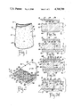
- FIG. 2 is an enlarged, partially broken away perspective view of a portion of the wall of the turbine blade or turbine vanes shown in FIG. 1;
- FIGS. 3a-3d are a series of views of the wall section shown in FIG. 2 illustrating the steps in the method of this invention
- FIG. 4 is a block diagram representation of the steps in the method of this invention.
- FIG. 5 is an enlarged view of the portion of FIG. 3d enclosed within the circle identified by the reference character 5 in FIG. 3d.
- a turbine blade 10 has a transpiration cooled, airfoil shaped flow directing portion 12.
- the blade 10 is representative of other flow directing elements in gas turbine engines such as turbine vanes and nozzle vanes.
- the flow directing portion 12 includes an airfoil-shaped spar wall 14 which forms the load carrying structure or backbone of the blade and a sheath 16 of porous metal.
- the sheath 16 has an outer surface 18, an inner surface 20, and a plurality of pores 22 which extend through the sheath and open through both the inner and the outer surfaces 20 and 18.
- the sheath may include multiple laminae such as described in the aforesaid U.S. Pat. No. 3,606,573.
- gaseous coolant will flow through the pores 22 toward the outer surface.
- the spar wall 14 surrounds a coolant plenum 40 within the blade 10 and includes an inner surface 42 facing the coolant plenum and an outer surface 44 facing the sheath 16.
- the spar wall 14 has a final or design thickness T F , FIG. 2, from the inner surface 42 to the outer surface 44, calculated to provide the required load carrying capability with a minimum rotating mass.
- the outer surface 44 of the spar wall has a plurality of coolant channels 46 or passages therein facing the inner surface 20 of the sheath.
- the channels 46 are interrupted by an array of pedestals 48 integral with the spar wall which terminate at the outer surface 44 of the spar wall.
- a plurality of holes 50 through the spar wall 14 extend from the inner surface 42 of the spar wall to the channels 46 between the pedestals 48.
- the sheath 16 is attached to the outer surface of the spar wall 14 through a plurality of diffusion bonds between the inner surface 20 of the sheath and respective ones of the pedestals 48.
- the turbine blade 10 is cooled during engine operation as follows. Compressed air from the compressor of the engine is directed to the coolant plenum 40. The air pressure in the coolant plenum exceeds the gas pressure in the hot gas flow path around the turbine blade so that cooling air migrates radially outward through the spar wall 14 and the sheath 16. As the cooling air migrates from the coolant plenum to the hot gas flow path, heat is absorbed from the blade and carried away with the hot gases.
- the sheath 16 is pre-formed generally to the airfoil shape of the spar wall 14.
- the spar wall 14 is pre-formed by casting or casting/electrochemical machining techniques to a configuration, FIG. 3a, wherein the channels 46 and the pedestals 48 are fully defined.
- the spar wall 14 has a pre-form or intermediate wall thickness T I , FIGS. 3a-3c, which exceeds the design thickness T F , FIGS. 2 and 3d, by an etch depth dimension T D , FIGS. 3a-3c.
- the intermediate wall thickness T I is illustrated in phantom line in FIG. 2.
- the steps of pre-forming the sheath 16 to the general airfoil shape of the spar wall and of pre-forming the spar wall 14 are generally conventional and are represented by the boxes 58 and 60, respectively, in the schematic process diagram, FIG. 4.
- the spar wall 14 undergoes an electro-chemical drilling, laser drilling, or electric discharge machining operation whereby a plurality of incomplete holes 62, FIGS. 3b-3c, are formed in the bottoms of some of the channels 46.
- the incomplete holes 62 are machined to a depth relative to the outer surface 44 of the spar wall which locates a bottom 64, FIG. 3b, of each incomplete hole at a depth equal to the design thickness T F of the spar wall.
- the step of forming the incomplete holes 62 is represented by the box 66 in the schematic process diagram, FIG. 4.
- the pre-formed metal sheath 16 is disposed over the spar wall 14 with the inner surface 20 of the sheath facing the outer surface 44 of the spar wall.
- the pedestals 48 are located between the pores 22.
- the sheath and spar wall are then disposed in a fixture, as for example the fixture described in the aforesaid U.S. Pat. No. 4,042,162, capable of applying high compressive pressure on the outer surface 18 of the sheath.
- the coolant plenum 40 is sealed except for an inlet, not shown, connected to a source of a pressure medium, such as a source of high pressure inert gas.
- the two are heated to a uniformly high diffusion bonding temperature of on the order of 2000° F. while uniform compressive pressure forces represented by the arrows 68, FIG. 3c, are exerted on the outer surface 18 of the sheath 16.
- the pressure forces 68 press the inner surface 20 of the sheath against the outer surface 44 of the spar wall at the pedestals 48 so that, in the presence of high temperature, a bond at the atomic level develops between the sheath and the spar wall.
- the inert gas pressure medium is introduced into the coolant plenum 40 at high pressure so that uniformly distributed outwardly directed pressure forces represented by the arrows 70, FIG. 3c, react against the imperforate inner surface of the spar wall.
- the pressure forces 70 reinforce the spar wall against the compressive forces 68 so that, during HIP bonding, neither the spar wall or the sheath are collapsed or distorted.
- the pressure forces 68 on the outer surface 18 are relieved and the pressure medium is evacuated from the coolant plenum 40 to relieve the pressure forces 70.
- the reinforced HIP bonding step just described is represented by the box 72 in the schematic process diagram, FIG. 4.
- the spar wall 14 is chemically machined from within the coolant plenum to decrease the thickness of the spar wall from the intermediate thickness T I to the design thickness T F .
- an appropriate chemical etchant may be introduced into the coolant plenum 40 in a strength and for a time duration sufficient to remove material from the imperforate inner surface of the spar wall to a depth equal to the etch depth dimension T D .
- the bottoms 64 of the incomplete holes 62 are also removed so that the incomplete holes 62 become the complete holes 50.
- the chemical removal of material from the spar wall to the etch depth dimension T D is represented by the box 74 in the schematic process diagram, FIG. 4.
- the final step in the fabrication method according to this invention may be an electro-chemical or a chemical/electro-chemical etch.
- electro-chemical etching the coolant plenum 40 is filled with an electrolyte and an electrode, not shown, is disposed in the middle of the coolant plenum.
- Current at a first current density is then passed between the center electrode and the spar wall during which current passage material is removed from the spar wall to a dpeth corresponding to the etch depth dimension T D .
- current is concentrated generally at an annular remnant 76 of the bottom 64 of each of the incomplete holes 62.
- the current density between the spar wall and the center electrode is then reduced to effect gradual elimination of the remnants 76 without enlarging the incomplete holes 62 where they intersect the inner surface 42 of the spar wall.
Landscapes
- Engineering & Computer Science (AREA)
- Mechanical Engineering (AREA)
- General Engineering & Computer Science (AREA)
- Turbine Rotor Nozzle Sealing (AREA)
Abstract
Description
Claims (3)
Priority Applications (1)
| Application Number | Priority Date | Filing Date | Title |
|---|---|---|---|
| US07/086,940 US4768700A (en) | 1987-08-17 | 1987-08-17 | Diffusion bonding method |
Applications Claiming Priority (1)
| Application Number | Priority Date | Filing Date | Title |
|---|---|---|---|
| US07/086,940 US4768700A (en) | 1987-08-17 | 1987-08-17 | Diffusion bonding method |
Publications (1)
| Publication Number | Publication Date |
|---|---|
| US4768700A true US4768700A (en) | 1988-09-06 |
Family
ID=22201879
Family Applications (1)
| Application Number | Title | Priority Date | Filing Date |
|---|---|---|---|
| US07/086,940 Expired - Fee Related US4768700A (en) | 1987-08-17 | 1987-08-17 | Diffusion bonding method |
Country Status (1)
| Country | Link |
|---|---|
| US (1) | US4768700A (en) |
Cited By (27)
| Publication number | Priority date | Publication date | Assignee | Title |
|---|---|---|---|---|
| US5083371A (en) * | 1990-09-14 | 1992-01-28 | United Technologies Corporation | Hollow metal article fabrication |
| US5297937A (en) * | 1991-08-23 | 1994-03-29 | Mitsubishi Jukogyo Kabushiki Kaisha | Hollow fan moving blade |
| US5586866A (en) * | 1994-08-26 | 1996-12-24 | Abb Management Ag | Baffle-cooled wall part |
| WO1999011420A1 (en) * | 1997-08-29 | 1999-03-11 | Siemens Aktiengesellschaft | Gas turbine vane and method for producing a gas turbine vane |
| DE19740502A1 (en) * | 1997-09-15 | 1999-03-18 | Fraunhofer Ges Forschung | Method for producing a component with a surface-near flow channel system for liquids and/or gases |
| WO1999033605A2 (en) * | 1997-10-27 | 1999-07-08 | Siemens Westinghouse Power Corporation | Turbine components with skin bonded to substrates |
| US6003756A (en) * | 1997-10-21 | 1999-12-21 | Allison Advanced Development Company | Airfoil for gas a turbine engine and method of manufacture |
| EP1001137A2 (en) * | 1998-11-16 | 2000-05-17 | General Electric Company | Axial serpentine cooled airfoil |
| WO2001000964A1 (en) * | 1999-06-29 | 2001-01-04 | Allison Advanced Development Company | Cooled airfoil |
| US6171711B1 (en) * | 1997-07-02 | 2001-01-09 | United Technologies Corporation | Apertured article preconditioned for recoating |
| EP1091092A2 (en) * | 1999-10-05 | 2001-04-11 | United Technologies Corporation | Method and apparatus for cooling a wall within a gas turbine engine |
| US6254334B1 (en) | 1999-10-05 | 2001-07-03 | United Technologies Corporation | Method and apparatus for cooling a wall within a gas turbine engine |
| US6325871B1 (en) | 1997-10-27 | 2001-12-04 | Siemens Westinghouse Power Corporation | Method of bonding cast superalloys |
| EP1267038A2 (en) * | 2001-06-14 | 2002-12-18 | Rolls-Royce Plc | Air cooled aerofoil |
| EP1375824A2 (en) * | 2002-06-19 | 2004-01-02 | United Technologies Corporation | Linked, non-plugging cooling microcircuits |
| EP1452264A1 (en) * | 2003-02-27 | 2004-09-01 | Kawasaki Jukogyo Kabushiki Kaisha | Method of manufacturing gas turbine part using porous metal |
| US20050212331A1 (en) * | 2004-03-23 | 2005-09-29 | Nissan Motor Co., Ltd. | Engine hood for automobiles |
| EP1629938A3 (en) * | 2004-08-26 | 2006-06-14 | United Technologies Corporation | Turbine engine component manufacture |
| EP1445424A3 (en) * | 2003-02-05 | 2006-12-27 | United Technologies Corporation | Microcircuit cooling for a turbine blade tip |
| US20100080687A1 (en) * | 2008-09-26 | 2010-04-01 | Siemens Power Generation, Inc. | Multiple Piece Turbine Engine Airfoil with a Structural Spar |
| US20100226762A1 (en) * | 2006-09-20 | 2010-09-09 | United Technologies Corporation | Structural members in a pedestal array |
| US20110182761A1 (en) * | 2008-03-20 | 2011-07-28 | Advanced Interactive Materials Science Limited | Stator for use in helicoidal motor |
| US20110236221A1 (en) * | 2010-03-26 | 2011-09-29 | Campbell Christian X | Four-Wall Turbine Airfoil with Thermal Strain Control for Reduced Cycle Fatigue |
| US20110259017A1 (en) * | 2010-04-22 | 2011-10-27 | General Electric Company | Hot gas path component cooling system |
| CN102554564A (en) * | 2010-11-23 | 2012-07-11 | 通用电气公司 | Turbine components with cooling features and methods of manufacturing the same |
| US20130185938A1 (en) * | 2010-10-05 | 2013-07-25 | Snecma | Method for manufacturing a metal part |
| US8727203B2 (en) | 2010-09-16 | 2014-05-20 | Howmedica Osteonics Corp. | Methods for manufacturing porous orthopaedic implants |
Citations (5)
| Publication number | Priority date | Publication date | Assignee | Title |
|---|---|---|---|---|
| US3606573A (en) * | 1969-08-15 | 1971-09-20 | Gen Motors Corp | Porous laminate |
| US3623204A (en) * | 1970-02-02 | 1971-11-30 | Gen Motors Corp | Method of fabricating hollow gas turbine blades |
| US3700418A (en) * | 1969-11-24 | 1972-10-24 | Gen Motors Corp | Cooled airfoil and method of making it |
| US4042162A (en) * | 1975-07-11 | 1977-08-16 | General Motors Corporation | Airfoil fabrication |
| US4383854A (en) * | 1980-12-29 | 1983-05-17 | General Electric Company | Method of creating a controlled interior surface configuration of passages within a substrate |
-
1987
- 1987-08-17 US US07/086,940 patent/US4768700A/en not_active Expired - Fee Related
Patent Citations (5)
| Publication number | Priority date | Publication date | Assignee | Title |
|---|---|---|---|---|
| US3606573A (en) * | 1969-08-15 | 1971-09-20 | Gen Motors Corp | Porous laminate |
| US3700418A (en) * | 1969-11-24 | 1972-10-24 | Gen Motors Corp | Cooled airfoil and method of making it |
| US3623204A (en) * | 1970-02-02 | 1971-11-30 | Gen Motors Corp | Method of fabricating hollow gas turbine blades |
| US4042162A (en) * | 1975-07-11 | 1977-08-16 | General Motors Corporation | Airfoil fabrication |
| US4383854A (en) * | 1980-12-29 | 1983-05-17 | General Electric Company | Method of creating a controlled interior surface configuration of passages within a substrate |
Cited By (47)
| Publication number | Priority date | Publication date | Assignee | Title |
|---|---|---|---|---|
| US5083371A (en) * | 1990-09-14 | 1992-01-28 | United Technologies Corporation | Hollow metal article fabrication |
| US5297937A (en) * | 1991-08-23 | 1994-03-29 | Mitsubishi Jukogyo Kabushiki Kaisha | Hollow fan moving blade |
| US5586866A (en) * | 1994-08-26 | 1996-12-24 | Abb Management Ag | Baffle-cooled wall part |
| US6171711B1 (en) * | 1997-07-02 | 2001-01-09 | United Technologies Corporation | Apertured article preconditioned for recoating |
| WO1999011420A1 (en) * | 1997-08-29 | 1999-03-11 | Siemens Aktiengesellschaft | Gas turbine vane and method for producing a gas turbine vane |
| US6582194B1 (en) | 1997-08-29 | 2003-06-24 | Siemens Aktiengesellschaft | Gas-turbine blade and method of manufacturing a gas-turbine blade |
| DE19740502A1 (en) * | 1997-09-15 | 1999-03-18 | Fraunhofer Ges Forschung | Method for producing a component with a surface-near flow channel system for liquids and/or gases |
| US6003756A (en) * | 1997-10-21 | 1999-12-21 | Allison Advanced Development Company | Airfoil for gas a turbine engine and method of manufacture |
| US6003754A (en) * | 1997-10-21 | 1999-12-21 | Allison Advanced Development Co. | Airfoil for a gas turbine engine and method of manufacture |
| US6638639B1 (en) | 1997-10-27 | 2003-10-28 | Siemens Westinghouse Power Corporation | Turbine components comprising thin skins bonded to superalloy substrates |
| US6325871B1 (en) | 1997-10-27 | 2001-12-04 | Siemens Westinghouse Power Corporation | Method of bonding cast superalloys |
| WO1999033605A2 (en) * | 1997-10-27 | 1999-07-08 | Siemens Westinghouse Power Corporation | Turbine components with skin bonded to substrates |
| WO1999033605A3 (en) * | 1997-10-27 | 1999-09-10 | Siemens Westinghouse Power | Turbine components with skin bonded to substrates |
| US6331217B1 (en) | 1997-10-27 | 2001-12-18 | Siemens Westinghouse Power Corporation | Turbine blades made from multiple single crystal cast superalloy segments |
| EP1001137A2 (en) * | 1998-11-16 | 2000-05-17 | General Electric Company | Axial serpentine cooled airfoil |
| EP1001137A3 (en) * | 1998-11-16 | 2001-10-10 | General Electric Company | Axial serpentine cooled airfoil |
| WO2001000964A1 (en) * | 1999-06-29 | 2001-01-04 | Allison Advanced Development Company | Cooled airfoil |
| US6213714B1 (en) * | 1999-06-29 | 2001-04-10 | Allison Advanced Development Company | Cooled airfoil |
| US6254334B1 (en) | 1999-10-05 | 2001-07-03 | United Technologies Corporation | Method and apparatus for cooling a wall within a gas turbine engine |
| US6402470B1 (en) | 1999-10-05 | 2002-06-11 | United Technologies Corporation | Method and apparatus for cooling a wall within a gas turbine engine |
| EP1091092A3 (en) * | 1999-10-05 | 2004-03-03 | United Technologies Corporation | Method and apparatus for cooling a wall within a gas turbine engine |
| US6514042B2 (en) | 1999-10-05 | 2003-02-04 | United Technologies Corporation | Method and apparatus for cooling a wall within a gas turbine engine |
| EP1091092A2 (en) * | 1999-10-05 | 2001-04-11 | United Technologies Corporation | Method and apparatus for cooling a wall within a gas turbine engine |
| EP1267038A3 (en) * | 2001-06-14 | 2005-01-05 | Rolls-Royce Plc | Air cooled aerofoil |
| EP1267038A2 (en) * | 2001-06-14 | 2002-12-18 | Rolls-Royce Plc | Air cooled aerofoil |
| EP1375824A3 (en) * | 2002-06-19 | 2004-09-08 | United Technologies Corporation | Linked, non-plugging cooling microcircuits |
| EP1375824A2 (en) * | 2002-06-19 | 2004-01-02 | United Technologies Corporation | Linked, non-plugging cooling microcircuits |
| EP1445424A3 (en) * | 2003-02-05 | 2006-12-27 | United Technologies Corporation | Microcircuit cooling for a turbine blade tip |
| EP1452264A1 (en) * | 2003-02-27 | 2004-09-01 | Kawasaki Jukogyo Kabushiki Kaisha | Method of manufacturing gas turbine part using porous metal |
| US20040168786A1 (en) * | 2003-02-27 | 2004-09-02 | Kawasaki Jukogyo Kabushiki Kaisha | Method of manufacturing gas turbine part using porous metal |
| US7390055B2 (en) * | 2004-03-23 | 2008-06-24 | Nissan Motor Co., Ltd. | Engine hood for automobiles |
| US20050212331A1 (en) * | 2004-03-23 | 2005-09-29 | Nissan Motor Co., Ltd. | Engine hood for automobiles |
| EP1629938A3 (en) * | 2004-08-26 | 2006-06-14 | United Technologies Corporation | Turbine engine component manufacture |
| US7441331B2 (en) | 2004-08-26 | 2008-10-28 | United Technologies Corporation | Turbine engine component manufacture methods |
| US9133715B2 (en) * | 2006-09-20 | 2015-09-15 | United Technologies Corporation | Structural members in a pedestal array |
| US20100226762A1 (en) * | 2006-09-20 | 2010-09-09 | United Technologies Corporation | Structural members in a pedestal array |
| US20110182761A1 (en) * | 2008-03-20 | 2011-07-28 | Advanced Interactive Materials Science Limited | Stator for use in helicoidal motor |
| US20100080687A1 (en) * | 2008-09-26 | 2010-04-01 | Siemens Power Generation, Inc. | Multiple Piece Turbine Engine Airfoil with a Structural Spar |
| US8033790B2 (en) | 2008-09-26 | 2011-10-11 | Siemens Energy, Inc. | Multiple piece turbine engine airfoil with a structural spar |
| US8535004B2 (en) * | 2010-03-26 | 2013-09-17 | Siemens Energy, Inc. | Four-wall turbine airfoil with thermal strain control for reduced cycle fatigue |
| US20110236221A1 (en) * | 2010-03-26 | 2011-09-29 | Campbell Christian X | Four-Wall Turbine Airfoil with Thermal Strain Control for Reduced Cycle Fatigue |
| US20110259017A1 (en) * | 2010-04-22 | 2011-10-27 | General Electric Company | Hot gas path component cooling system |
| US8651805B2 (en) * | 2010-04-22 | 2014-02-18 | General Electric Company | Hot gas path component cooling system |
| US8727203B2 (en) | 2010-09-16 | 2014-05-20 | Howmedica Osteonics Corp. | Methods for manufacturing porous orthopaedic implants |
| US20130185938A1 (en) * | 2010-10-05 | 2013-07-25 | Snecma | Method for manufacturing a metal part |
| US9296072B2 (en) * | 2010-10-05 | 2016-03-29 | Snecma | Method for manufacturing a metal part |
| CN102554564A (en) * | 2010-11-23 | 2012-07-11 | 通用电气公司 | Turbine components with cooling features and methods of manufacturing the same |
Similar Documents
| Publication | Publication Date | Title |
|---|---|---|
| US4768700A (en) | Diffusion bonding method | |
| US6837417B2 (en) | Method of sealing a hollow cast member | |
| US4501053A (en) | Method of making rotor blade for a rotary machine | |
| US4659288A (en) | Dual alloy radial turbine rotor with hub material exposed in saddle regions of blade ring | |
| EP1621727B1 (en) | Turbine rotor blade and gas turbine engine rotor assembly comprising such blades | |
| US4650399A (en) | Rotor blade for a rotary machine | |
| US7441585B2 (en) | Apparatus and method for reducing operating stress in a turbine blade and the like | |
| US4604780A (en) | Method of fabricating a component having internal cooling passages | |
| US4314794A (en) | Transpiration cooled blade for a gas turbine engine | |
| US4422229A (en) | Method of making an airfoil member for a gas turbine engine | |
| US8506256B1 (en) | Thin walled turbine blade and process for making the blade | |
| US5711068A (en) | Method of manufacturing a blade | |
| US5176499A (en) | Photoetched cooling slots for diffusion bonded airfoils | |
| US4096615A (en) | Turbine rotor fabrication | |
| JP3456534B2 (en) | Coolable airfoil and core for casting the airfoil | |
| CA1132339A (en) | Manufacture of composite turbine rotors | |
| RU2268387C2 (en) | Method of manufacturing combustion chamber | |
| US4575327A (en) | Enclosure for the hot-isostatic pressing of highly stressed workpieces of complex shape for turbomachines | |
| US20060024164A1 (en) | Method and apparatus for cooling gas turbine engine rotor blades | |
| US20040112564A1 (en) | Methods and apparatus for fabricating turbine engine airfoils | |
| US4183456A (en) | Method of fabricating liquid cooled gas turbine components | |
| JPS6137387A (en) | Manufacture of integral multi-alloy part | |
| EP0990481A1 (en) | Co-machined bonded airfoil | |
| US4383809A (en) | Capsule for use in hot isostatic pressing of workpieces | |
| US10981221B2 (en) | Method and assembly for forming components using a jacketed core |
Legal Events
| Date | Code | Title | Description |
|---|---|---|---|
| AS | Assignment |
Owner name: GENERAL MOTORS CORPORATION, DETROIT, MI A CORP. OF Free format text: ASSIGNMENT OF ASSIGNORS INTEREST.;ASSIGNOR:CHEN, YU-LIN;REEL/FRAME:004784/0157 Effective date: 19870730 Owner name: GENERAL MOTORS CORPORATION, A CORP. OF DE,MICHIGAN Free format text: ASSIGNMENT OF ASSIGNORS INTEREST;ASSIGNOR:CHEN, YU-LIN;REEL/FRAME:004784/0157 Effective date: 19870730 |
|
| FPAY | Fee payment |
Year of fee payment: 4 |
|
| AS | Assignment |
Owner name: AEC ACQUISTION CORPORATION, INDIANA Free format text: ASSIGNMENT OF ASSIGNORS INTEREST;ASSIGNOR:GENERAL MOTORS CORPORATION;REEL/FRAME:006783/0275 Effective date: 19931130 Owner name: CHEMICAL BANK, AS AGENT, NEW YORK Free format text: ASSIGNMENT OF ASSIGNORS INTEREST;ASSIGNOR:AEC ACQUISITION CORPORATION;REEL/FRAME:006779/0728 Effective date: 19931130 |
|
| AS | Assignment |
Owner name: ALLISON ENGINE COMPANY, INC., INDIANA Free format text: CHANGE OF NAME;ASSIGNOR:AEC ACQUISTITION CORPORATION A/K/A AEC ACQUISTION CORPORATION;REEL/FRAME:007118/0906 Effective date: 19931201 |
|
| FPAY | Fee payment |
Year of fee payment: 8 |
|
| REMI | Maintenance fee reminder mailed | ||
| LAPS | Lapse for failure to pay maintenance fees | ||
| FP | Expired due to failure to pay maintenance fee |
Effective date: 20000906 |
|
| STCH | Information on status: patent discontinuation |
Free format text: PATENT EXPIRED DUE TO NONPAYMENT OF MAINTENANCE FEES UNDER 37 CFR 1.362 |