US4742855A - Woodworking router - Google Patents
Woodworking router Download PDFInfo
- Publication number
- US4742855A US4742855A US07/042,730 US4273087A US4742855A US 4742855 A US4742855 A US 4742855A US 4273087 A US4273087 A US 4273087A US 4742855 A US4742855 A US 4742855A
- Authority
- US
- United States
- Prior art keywords
- router
- collar
- head
- dust collection
- dust
- Prior art date
- Legal status (The legal status is an assumption and is not a legal conclusion. Google has not performed a legal analysis and makes no representation as to the accuracy of the status listed.)
- Expired - Fee Related
Links
Images


Classifications
-
- B—PERFORMING OPERATIONS; TRANSPORTING
- B23—MACHINE TOOLS; METAL-WORKING NOT OTHERWISE PROVIDED FOR
- B23Q—DETAILS, COMPONENTS, OR ACCESSORIES FOR MACHINE TOOLS, e.g. ARRANGEMENTS FOR COPYING OR CONTROLLING; MACHINE TOOLS IN GENERAL CHARACTERISED BY THE CONSTRUCTION OF PARTICULAR DETAILS OR COMPONENTS; COMBINATIONS OR ASSOCIATIONS OF METAL-WORKING MACHINES, NOT DIRECTED TO A PARTICULAR RESULT
- B23Q11/00—Accessories fitted to machine tools for keeping tools or parts of the machine in good working condition or for cooling work; Safety devices specially combined with or arranged in, or specially adapted for use in connection with, machine tools
- B23Q11/0078—Safety devices protecting the operator, e.g. against accident or noise
- B23Q11/0092—Safety devices protecting the operator, e.g. against accident or noise actuating braking or stopping means
-
- B—PERFORMING OPERATIONS; TRANSPORTING
- B23—MACHINE TOOLS; METAL-WORKING NOT OTHERWISE PROVIDED FOR
- B23Q—DETAILS, COMPONENTS, OR ACCESSORIES FOR MACHINE TOOLS, e.g. ARRANGEMENTS FOR COPYING OR CONTROLLING; MACHINE TOOLS IN GENERAL CHARACTERISED BY THE CONSTRUCTION OF PARTICULAR DETAILS OR COMPONENTS; COMBINATIONS OR ASSOCIATIONS OF METAL-WORKING MACHINES, NOT DIRECTED TO A PARTICULAR RESULT
- B23Q11/00—Accessories fitted to machine tools for keeping tools or parts of the machine in good working condition or for cooling work; Safety devices specially combined with or arranged in, or specially adapted for use in connection with, machine tools
- B23Q11/0042—Devices for removing chips
- B23Q11/0046—Devices for removing chips by sucking
-
- B—PERFORMING OPERATIONS; TRANSPORTING
- B23—MACHINE TOOLS; METAL-WORKING NOT OTHERWISE PROVIDED FOR
- B23Q—DETAILS, COMPONENTS, OR ACCESSORIES FOR MACHINE TOOLS, e.g. ARRANGEMENTS FOR COPYING OR CONTROLLING; MACHINE TOOLS IN GENERAL CHARACTERISED BY THE CONSTRUCTION OF PARTICULAR DETAILS OR COMPONENTS; COMBINATIONS OR ASSOCIATIONS OF METAL-WORKING MACHINES, NOT DIRECTED TO A PARTICULAR RESULT
- B23Q11/00—Accessories fitted to machine tools for keeping tools or parts of the machine in good working condition or for cooling work; Safety devices specially combined with or arranged in, or specially adapted for use in connection with, machine tools
- B23Q11/08—Protective coverings for parts of machine tools; Splash guards
-
- B—PERFORMING OPERATIONS; TRANSPORTING
- B23—MACHINE TOOLS; METAL-WORKING NOT OTHERWISE PROVIDED FOR
- B23Q—DETAILS, COMPONENTS, OR ACCESSORIES FOR MACHINE TOOLS, e.g. ARRANGEMENTS FOR COPYING OR CONTROLLING; MACHINE TOOLS IN GENERAL CHARACTERISED BY THE CONSTRUCTION OF PARTICULAR DETAILS OR COMPONENTS; COMBINATIONS OR ASSOCIATIONS OF METAL-WORKING MACHINES, NOT DIRECTED TO A PARTICULAR RESULT
- B23Q5/00—Driving or feeding mechanisms; Control arrangements therefor
- B23Q5/02—Driving main working members
- B23Q5/04—Driving main working members rotary shafts, e.g. working-spindles
- B23Q5/10—Driving main working members rotary shafts, e.g. working-spindles driven essentially by electrical means
-
- B—PERFORMING OPERATIONS; TRANSPORTING
- B27—WORKING OR PRESERVING WOOD OR SIMILAR MATERIAL; NAILING OR STAPLING MACHINES IN GENERAL
- B27C—PLANING, DRILLING, MILLING, TURNING OR UNIVERSAL MACHINES FOR WOOD OR SIMILAR MATERIAL
- B27C5/00—Machines designed for producing special profiles or shaped work, e.g. by rotary cutters; Equipment therefor
- B27C5/10—Portable hand-operated wood-milling machines; Routers
-
- Y—GENERAL TAGGING OF NEW TECHNOLOGICAL DEVELOPMENTS; GENERAL TAGGING OF CROSS-SECTIONAL TECHNOLOGIES SPANNING OVER SEVERAL SECTIONS OF THE IPC; TECHNICAL SUBJECTS COVERED BY FORMER USPC CROSS-REFERENCE ART COLLECTIONS [XRACs] AND DIGESTS
- Y10—TECHNICAL SUBJECTS COVERED BY FORMER USPC
- Y10T—TECHNICAL SUBJECTS COVERED BY FORMER US CLASSIFICATION
- Y10T409/00—Gear cutting, milling, or planing
- Y10T409/30—Milling
- Y10T409/304088—Milling with means to remove chip
Definitions
- the invention relates to woodworking router machines, and particularly to such machines with automatic collection of the dust and debris created during routing, and transfer of that dust and debris to factory dust extraction equipment.
- GB No. 2117510 describes a router comprising an electric motor covered with an air suction chamber and mounted for vertical movement. Air suction cools the motor and removes the chips produced.
- the motor and the suction chamber are integral with on attachment which is vertically movable in operation. Fine adjustment of the position of the motor and chamber in relation to the attachment is provided by a worm shaft and gear, but the position of the motor in relation to the chamber cannot be varied.
- means are provided for moving the dust collection collar vertically relative to the router head between a raised position in which the router head is exposed for tool changing and a lowered safety position in which the collar provides a safety guard around the router head.
- the dust extraction duct in the router of the invention is coaxial with and surrounds the electric motor, which provides a variety of distinct advantages.
- the means for moving the dust collection collar can move the collar over as large a range of movement as is desired without the collar fouling the motor and router head.
- the moving means is a fluid-operated means such as a pneumatic ram, and is interlinked with the control circuit to maintain the collar in its lowered safety position while the motor is running.
- That safety position may be a defined height relative to the worktable so that a brush around the dust collection collar brushes against the table in use, or may be a defined height relative to the router head, always to shroud the router head for enhanced safety.
- the stroke of the pneumatic ram provides the sole design restriction on the vertical movement of the collar, so that the raised position may be any height necessary to permit easy tool changing.
- Another extremely significant and unexpected advantage is the efficiency of the dust extraction air stream to cool the motor. It has been found that the electric motor in the router of the invention is so efficiently cooled by the extraction air that it can be designed as a fanless motor, with the sole cooling means being the flow of dust extraction air through the dust extraction duct. Indeed the running temperature of such a motor can be reduced by up to 30% as compared with a conventional fan-cooled motor, and there is also a significant noise reduction.
- the motor cooling by dust extraction air is so efficient that it permits the motor chosen to be one braked by DC injection braking.
- This is a rapid form of braking normally associated with high heat generation and high running temperatures, but a router of the invention has been successfully tested through a prolonged repeat cycle of 30 seconds running; rapid DC injection braking (over 4 seconds); a short pause; and then rapid acceleration to running speed.
- Running temperatures were remarkably low, possibly due in part to the fact that the flow of cooling air from the factory dust collection equipment did not stop with the motor but continued throughout the cycle.
- a router according to the invention would have a conventional temperature-responsive cut-out device to stop the motor in the case of overheating, such as if the air supply were to fail.
- the dust collection collar Preferably there are three positions of the dust collection collar relative to the router head: the raised position for tool changing; the lowered safety position for establishing a safety guard around the router head during routing; and an even lower scavenge position for cleaning the bench.
- the dust collection collar completely covers the cutter at the end of the cutting cycle, for example when the operator is removing the workpiece from the worktable or loading a new workpiece.
- the raised position of the collar is established when the router head is itself raised out of line with the workpiece, and preferably only when to motor has stopped.
- the lowered safety position may be adjustable to suit individual tool heads, but once adjusted the collar always returns to the same safety position on actuation of its fluid-operated control means.
- the even lower position of the collar relative to the router head is an important preferred feature, establishing a very high degree of protection to the operator when the router head is raised. It also enables the router head to be raised to an inoperative position and the dust collection collar lowered into brushing contact with the worktable, so that a preprogrammed sweeping and cleaning of the table can be performed at regular intervals during routing--for example on completion of each article being worked.
- the router of the invention is significantly quieter and cooler than those previously known, and consequently more efficient. It permits manual or automatic tool change, and is safer than known routers insofar as the dust collection collar establishes an effective safety guard around the router head in use.
- the bristle length of a brush head depending from the collar may be short, as the working height of both the router head and the collar may be under microprocessor control to bring even short brush bristles into brushing contact with the workpiece or worktable in use.
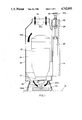
- FIG. 1 is an axial section through the working head of a router according to the invention, with the dust collection collar in its lowered safety position during routing;
- FIGS. 2 and 3 are axial sections taken transversely to that of FIG. 1 but with the collar in, respectively, its raised position for tool changing and its lowermost position for cleaning the worktable;
- FIG. 4 is a schematic vertical plan view of FIG. 1.
- FIG. 5 is a block diagram.
- FIG. 1 In the drawings there is shown a woodworking router in which an electric motor 10 drives an integral router head 12. A router tool is shown fitted to the router head in FIGS. 1 and 3, but has been removed in FIG. 2.
- the router head is mounted fast on a mounting slide 14 as seen in FIGS. 1 and 4, and the slide moves vertically in a rigid mast (not shown) of a main frame of the router, under CNC control.
- the control circuit of the present invention is of standard character and the constitution thereof, together with the usual valve members, is not considered to be a part of the present invention. In this manner the router head 12 can be raised and lowered relative to a worktable 16 under microprocessor control, as best illustrated by comparison of FIGS. 1 and 3.
- a dust extraction duct 18 Arranged coaxially around the electric motor 10 is a dust extraction duct 18 which supports at its lower end a dust collection collar 20. Depending from the collar 20 is an annular brush 22 the bristles of which likely engage the worktable 16 during routing as illustrated in FIG. 1.
- the dust extraction duct 18 terminates in an annular brim 24 for connection to factory dust extraction equipment (not shown).
- a pneumatic ram 26 Vertical movement of the dust extraction duct 18 and the dust collection collar 20 relative to the router head 12 is controlled by a pneumatic ram 26.
- a piston rod of the ram 26 engages beneath a shoulder 28 of a member which is fast to the duct 18 and collar 20, so that raising and lowering the duct and collar relative to the router head 12 is achieved simply by controlling the air supply to the ram 26 optionally under microprocessor control.
- the duct 18 and collar 20 are illustrated in FIG. 1 in a lowered safety position relative to the router head 12 in which the collar 20 provides a safety guard around the router head. In this position routing can be carried out, with the brushes 22 lightly brushing against the surface of the worktable 16.
- the actual height of the duct 18 and collar 20 relative to the router head 12 is established by means of an adjusting screw 30, adjustable by means of a handle 32, to take account of the actual depth of cut at the router head.
- the adjusting screw 30 and handle 32 are carried on a pivotting arm 36 as best seen in FIG. 4, and movement of the pivotting arm to the position shown in broken lines in FIGS. 1 and 4 is sufficient to bring the adjusting screw 30 out of its line of engagement with the stop surface 28, so that continued extension of the pneumatic ram 26 will result in a further raising of the duct 18 and collar 20 relative to the router head 12, to bring them to a tool changing position as illustrated in FIG. 2 in which the brush 22, collar 20 and duct 18 have all been raised to a level high enough to facilitate tool changing.
- FIG. 1 also illustrates the direction of air flow (34a) in an air passage 34 which extends completely around and axially of the electric motor 10.
- the dust extraction duct and collar 18 and 20 have basically three alternative positions relative to the router head 12.
- the collar 20 and brush 22 extend around the router head 12 as a safety guard.
- the fully raised position of FIG. 2 rapid and unhindered tool changing is facilitated.
- the extreme lowered position of FIG. 3 the router head 12 and router tool are raised well out of line with the workpiece, and the bristles of the brush 22 lightly contact the worktable.
- the worktable can be readily and rapidly cleaned by working the router head systematically over the whole of the worktable area. This cleaning may itself be under microprocessor control.
- the factory dust extraction air flows in the direction of the arrows 34a through the dust extraction dust as indicated by the arrows 34a. It has been found that this air flow is remarkably efficient for cooling the electric motor 10, which is therefore illustrated as a fanless electric motor.
Abstract
Description
Claims (10)
Applications Claiming Priority (2)
| Application Number | Priority Date | Filing Date | Title |
|---|---|---|---|
| GB8612789 | 1986-05-27 | ||
| GB8612789A GB2190876B (en) | 1986-05-27 | 1986-05-27 | Woodworking router |
Publications (1)
| Publication Number | Publication Date |
|---|---|
| US4742855A true US4742855A (en) | 1988-05-10 |
Family
ID=10598456
Family Applications (1)
| Application Number | Title | Priority Date | Filing Date |
|---|---|---|---|
| US07/042,730 Expired - Fee Related US4742855A (en) | 1986-05-27 | 1987-04-27 | Woodworking router |
Country Status (9)
| Country | Link |
|---|---|
| US (1) | US4742855A (en) |
| AU (1) | AU581567B2 (en) |
| CA (1) | CA1281618C (en) |
| CH (1) | CH673979A5 (en) |
| DK (1) | DK161058C (en) |
| FI (1) | FI81990C (en) |
| GB (1) | GB2190876B (en) |
| NO (1) | NO161899C (en) |
| SE (1) | SE464013B (en) |
Cited By (26)
| Publication number | Priority date | Publication date | Assignee | Title |
|---|---|---|---|---|
| DE3915312A1 (en) * | 1988-05-24 | 1989-12-07 | Scm Ind Spa | TOOL UNIT FOR WOODWORKING MACHINES |
| US4986703A (en) * | 1989-05-01 | 1991-01-22 | The United States Of America As Represented By The Department Of Health And Human Services | Auxiliary control technology for routers |
| US5017060A (en) * | 1990-04-16 | 1991-05-21 | Mitsubishi Metal Corporation | Rotary cutting tool |
| US5031678A (en) * | 1988-02-27 | 1991-07-16 | Robert Bosch Gmbh | Mortising machine |
| US5101875A (en) * | 1991-02-01 | 1992-04-07 | Ben Eckhold | Router base |
| US5311914A (en) * | 1993-04-14 | 1994-05-17 | Ritter Manufacturing, Inc. | Attachment for a portable router |
| US5370165A (en) * | 1993-04-14 | 1994-12-06 | Ritter Manufacturing, Inc. | Attachment for a portable router |
| US5503203A (en) * | 1993-04-14 | 1996-04-02 | Ritter Manufacturing, Inc. | Attachment for a portable router |
| US5662440A (en) * | 1996-08-08 | 1997-09-02 | Ryobi North America | Router attachment |
| US5993124A (en) * | 1997-07-10 | 1999-11-30 | Porter-Cable Corporation | Router dust-collection system |
| US6146066A (en) * | 1999-01-14 | 2000-11-14 | Yelton; Edwin C. | Dust collection router |
| US6161993A (en) * | 1999-09-14 | 2000-12-19 | Campian; Jonathon | Cutting machine assembly |
| US6182723B1 (en) * | 1998-11-16 | 2001-02-06 | Porter-Cable Corporation | Switchable router brake system |
| US6196775B1 (en) * | 1999-05-24 | 2001-03-06 | Gerber Scientific Products, Inc. | Apparatus for extracting chips from slots cut into a substrate |
| US6601621B2 (en) | 2001-04-18 | 2003-08-05 | Black & Decker Inc. | Portable Power Planer |
| US6808341B2 (en) * | 2001-05-29 | 2004-10-26 | Nailermate Enterprise Corp. | Pneumatic edge trimming machine |
| GB2411619A (en) * | 2004-03-02 | 2005-09-07 | Black & Decker Inc | Planer and thicknesser |
| US20090032138A1 (en) * | 2007-08-03 | 2009-02-05 | Credo Technology Corporation | Vacuum attachment for rotary tool |
| US20100170538A1 (en) * | 2008-12-09 | 2010-07-08 | Credo Technology Corporation | Debris removal system for power tool |
| CN1748920B (en) * | 2004-09-13 | 2011-04-20 | 住友化学株式会社 | Cutting part and mirror processing device with said cutting part |
| US7971611B1 (en) | 2010-10-18 | 2011-07-05 | Wells William W | Combination dust extractor and support plate for table mounted routers |
| US20130312991A1 (en) * | 2012-05-25 | 2013-11-28 | Fuji Jukogyo Kabushiki Kaisha | Attachment for dust collection for cutting machining, dust collecting duct for machine tools, tool holder for machine tools, and machine tool |
| US20130330144A1 (en) * | 2011-03-04 | 2013-12-12 | Kraussmaffei Technologies Gmbh | Device for the extraction, parallel to the process, of processing products arising during the processing of a workpiece |
| US8708624B1 (en) * | 2010-05-05 | 2014-04-29 | Frank Marusiak | Router chip guard |
| US10016868B2 (en) * | 2016-01-08 | 2018-07-10 | Woodcraft Solutions Llc | Dust and debris collection system for woodworking routers |
| US10088828B2 (en) * | 2014-10-24 | 2018-10-02 | Okuma Corporation | Controlling load ratio induced shut-down conditions in numerical control devices |
Families Citing this family (2)
| Publication number | Priority date | Publication date | Assignee | Title |
|---|---|---|---|---|
| US5779407A (en) * | 1996-02-01 | 1998-07-14 | Lee Valley Tools Ltd. | Router table fence system |
| DE102016001745B4 (en) * | 2016-02-10 | 2021-03-04 | Michael Weinig Ag | Woodworking tool spindle and moulder with such a tool spindle |
Citations (7)
| Publication number | Priority date | Publication date | Assignee | Title |
|---|---|---|---|---|
| US3786846A (en) * | 1972-10-17 | 1974-01-22 | Danley Machine Corp | Shield assembly for router |
| US3837383A (en) * | 1972-11-09 | 1974-09-24 | K Ko | Dust collector and safety guard |
| US3880047A (en) * | 1973-03-22 | 1975-04-29 | Dosier Paul Ass Inc | Chip removal and hold-down device for lateral movement routers |
| US4051880A (en) * | 1976-10-29 | 1977-10-04 | The Singer Company | Dustless routers |
| US4200417A (en) * | 1977-04-06 | 1980-04-29 | Robert Bosch Gmbh | Arrangement for withdrawing particles of material removed by a working tool |
| US4244669A (en) * | 1977-06-25 | 1981-01-13 | Aristo-Werke Dennert & Pape Kg (Gmbh & Co.) | Cutter head for cutting templates from cardboards, plastics, and the like |
| US4397342A (en) * | 1981-07-29 | 1983-08-09 | North Joe E | Pin-router mounting device and method |
Family Cites Families (2)
| Publication number | Priority date | Publication date | Assignee | Title |
|---|---|---|---|---|
| DE3113913A1 (en) * | 1981-04-07 | 1982-10-28 | Günter Horst 7927 Sontheim Röhm | DEVICE FOR COLLECTING DRILL AT THE DRILLING SITE OF A DRILL |
| JPS58171908A (en) * | 1982-04-01 | 1983-10-08 | 株式会社平安鉄工所 | Dust collector of motor for working |
-
1986
- 1986-05-27 GB GB8612789A patent/GB2190876B/en not_active Expired
-
1987
- 1987-04-21 FI FI871742A patent/FI81990C/en not_active IP Right Cessation
- 1987-04-27 CA CA000535704A patent/CA1281618C/en not_active Expired - Fee Related
- 1987-04-27 US US07/042,730 patent/US4742855A/en not_active Expired - Fee Related
- 1987-04-29 AU AU72224/87A patent/AU581567B2/en not_active Ceased
- 1987-05-18 CH CH1894/87A patent/CH673979A5/de not_active IP Right Cessation
- 1987-05-26 DK DK270387A patent/DK161058C/en not_active IP Right Cessation
- 1987-05-26 NO NO872212A patent/NO161899C/en unknown
- 1987-05-26 SE SE8702200A patent/SE464013B/en not_active IP Right Cessation
Patent Citations (7)
| Publication number | Priority date | Publication date | Assignee | Title |
|---|---|---|---|---|
| US3786846A (en) * | 1972-10-17 | 1974-01-22 | Danley Machine Corp | Shield assembly for router |
| US3837383A (en) * | 1972-11-09 | 1974-09-24 | K Ko | Dust collector and safety guard |
| US3880047A (en) * | 1973-03-22 | 1975-04-29 | Dosier Paul Ass Inc | Chip removal and hold-down device for lateral movement routers |
| US4051880A (en) * | 1976-10-29 | 1977-10-04 | The Singer Company | Dustless routers |
| US4200417A (en) * | 1977-04-06 | 1980-04-29 | Robert Bosch Gmbh | Arrangement for withdrawing particles of material removed by a working tool |
| US4244669A (en) * | 1977-06-25 | 1981-01-13 | Aristo-Werke Dennert & Pape Kg (Gmbh & Co.) | Cutter head for cutting templates from cardboards, plastics, and the like |
| US4397342A (en) * | 1981-07-29 | 1983-08-09 | North Joe E | Pin-router mounting device and method |
Cited By (43)
| Publication number | Priority date | Publication date | Assignee | Title |
|---|---|---|---|---|
| US5031678A (en) * | 1988-02-27 | 1991-07-16 | Robert Bosch Gmbh | Mortising machine |
| DE3915312A1 (en) * | 1988-05-24 | 1989-12-07 | Scm Ind Spa | TOOL UNIT FOR WOODWORKING MACHINES |
| US4909293A (en) * | 1988-05-24 | 1990-03-20 | Scm Industria S.P.A. | Tool assembly for woodworking machines |
| US4986703A (en) * | 1989-05-01 | 1991-01-22 | The United States Of America As Represented By The Department Of Health And Human Services | Auxiliary control technology for routers |
| US5017060A (en) * | 1990-04-16 | 1991-05-21 | Mitsubishi Metal Corporation | Rotary cutting tool |
| US5101875A (en) * | 1991-02-01 | 1992-04-07 | Ben Eckhold | Router base |
| US5311914A (en) * | 1993-04-14 | 1994-05-17 | Ritter Manufacturing, Inc. | Attachment for a portable router |
| US5370165A (en) * | 1993-04-14 | 1994-12-06 | Ritter Manufacturing, Inc. | Attachment for a portable router |
| US5503203A (en) * | 1993-04-14 | 1996-04-02 | Ritter Manufacturing, Inc. | Attachment for a portable router |
| US5662440A (en) * | 1996-08-08 | 1997-09-02 | Ryobi North America | Router attachment |
| US5993124A (en) * | 1997-07-10 | 1999-11-30 | Porter-Cable Corporation | Router dust-collection system |
| US6182723B1 (en) * | 1998-11-16 | 2001-02-06 | Porter-Cable Corporation | Switchable router brake system |
| US6146066A (en) * | 1999-01-14 | 2000-11-14 | Yelton; Edwin C. | Dust collection router |
| US6196775B1 (en) * | 1999-05-24 | 2001-03-06 | Gerber Scientific Products, Inc. | Apparatus for extracting chips from slots cut into a substrate |
| US6161993A (en) * | 1999-09-14 | 2000-12-19 | Campian; Jonathon | Cutting machine assembly |
| US20050076972A1 (en) * | 2001-04-18 | 2005-04-14 | Barry Wixey | Multi-piece machine tool base |
| US6918419B2 (en) | 2001-04-18 | 2005-07-19 | Black & Decker Inc. | Portable power planer |
| US20040144446A1 (en) * | 2001-04-18 | 2004-07-29 | Barry Wixey | Portable power planer |
| US6708744B2 (en) | 2001-04-18 | 2004-03-23 | Black & Decker Inc. | Portable power planer |
| US20040250889A1 (en) * | 2001-04-18 | 2004-12-16 | Barry Wixey | Portable power planer |
| US6601621B2 (en) | 2001-04-18 | 2003-08-05 | Black & Decker Inc. | Portable Power Planer |
| US6886615B2 (en) | 2001-04-18 | 2005-05-03 | Black & Decker Inc. | Portable power planer |
| US7428917B2 (en) | 2001-04-18 | 2008-09-30 | Black & Decker Inc. | Portable power planer with height scale |
| US20060090816A1 (en) * | 2001-04-18 | 2006-05-04 | Barry Wixey | Portable power planer with height scale |
| US6808341B2 (en) * | 2001-05-29 | 2004-10-26 | Nailermate Enterprise Corp. | Pneumatic edge trimming machine |
| US20050194063A1 (en) * | 2004-03-02 | 2005-09-08 | Marcello Bettacchini | Planer & thicknesser |
| GB2411619A (en) * | 2004-03-02 | 2005-09-07 | Black & Decker Inc | Planer and thicknesser |
| US20080105333A1 (en) * | 2004-03-02 | 2008-05-08 | Marcello Bettacchini | Planer and thicknesser |
| US7527080B2 (en) | 2004-03-02 | 2009-05-05 | Black & Decker Inc. | Planer and thicknesser |
| US7588063B2 (en) | 2004-03-02 | 2009-09-15 | Black & Decker Inc. | Planer and thicknesser |
| CN1748920B (en) * | 2004-09-13 | 2011-04-20 | 住友化学株式会社 | Cutting part and mirror processing device with said cutting part |
| US20090032138A1 (en) * | 2007-08-03 | 2009-02-05 | Credo Technology Corporation | Vacuum attachment for rotary tool |
| US20100170538A1 (en) * | 2008-12-09 | 2010-07-08 | Credo Technology Corporation | Debris removal system for power tool |
| US8397342B2 (en) | 2008-12-09 | 2013-03-19 | Credo Technology Corporation | Debris removal system for power tool |
| US8834641B2 (en) | 2008-12-09 | 2014-09-16 | Credo Technology Corporation | Method of use for debris removal system for power tool |
| US8708624B1 (en) * | 2010-05-05 | 2014-04-29 | Frank Marusiak | Router chip guard |
| US7971611B1 (en) | 2010-10-18 | 2011-07-05 | Wells William W | Combination dust extractor and support plate for table mounted routers |
| US20130330144A1 (en) * | 2011-03-04 | 2013-12-12 | Kraussmaffei Technologies Gmbh | Device for the extraction, parallel to the process, of processing products arising during the processing of a workpiece |
| US9527182B2 (en) * | 2011-03-04 | 2016-12-27 | Kraussmaffei Technologies Gmbh | Device for the extraction, parallel to the process, of processing products arising during the processing of a workpiece |
| US20130312991A1 (en) * | 2012-05-25 | 2013-11-28 | Fuji Jukogyo Kabushiki Kaisha | Attachment for dust collection for cutting machining, dust collecting duct for machine tools, tool holder for machine tools, and machine tool |
| US9527181B2 (en) * | 2012-05-25 | 2016-12-27 | Fuji Jukogyo Kabushiki Kaisha | Attachment for dust collection for cutting machining, dust collecting duct for machine tools, tool holder for machine tools, and machine tool |
| US10088828B2 (en) * | 2014-10-24 | 2018-10-02 | Okuma Corporation | Controlling load ratio induced shut-down conditions in numerical control devices |
| US10016868B2 (en) * | 2016-01-08 | 2018-07-10 | Woodcraft Solutions Llc | Dust and debris collection system for woodworking routers |
Also Published As
| Publication number | Publication date |
|---|---|
| FI871742A0 (en) | 1987-04-21 |
| AU581567B2 (en) | 1989-02-23 |
| AU7222487A (en) | 1987-12-03 |
| FI81990C (en) | 1991-01-10 |
| FI81990B (en) | 1990-09-28 |
| GB8612789D0 (en) | 1986-07-02 |
| DK270387D0 (en) | 1987-05-26 |
| SE8702200D0 (en) | 1987-05-26 |
| SE8702200L (en) | 1987-11-28 |
| DK161058B (en) | 1991-05-27 |
| NO161899B (en) | 1989-07-03 |
| CA1281618C (en) | 1991-03-19 |
| DK161058C (en) | 1991-11-11 |
| SE464013B (en) | 1991-02-25 |
| DK270387A (en) | 1987-11-28 |
| GB2190876B (en) | 1989-12-06 |
| NO161899C (en) | 1989-10-11 |
| CH673979A5 (en) | 1990-04-30 |
| FI871742A (en) | 1987-11-28 |
| NO872212D0 (en) | 1987-05-26 |
| GB2190876A (en) | 1987-12-02 |
| NO872212L (en) | 1987-11-30 |
Similar Documents
| Publication | Publication Date | Title |
|---|---|---|
| US4742855A (en) | Woodworking router | |
| KR101894234B1 (en) | Milling Machine with chip removal tool | |
| GB2117510A (en) | Chip collecting means for tooling motor | |
| CN111299677B (en) | Large-scale double housing planer | |
| CN116765453A (en) | Numerical control vertical drilling machine with automatic chip removal function | |
| CN110816131B (en) | Multifunctional engraving machine | |
| CN215145826U (en) | Safe and convenient-to-clean laser cutting machine | |
| CN217252936U (en) | Radial drill that security performance is good | |
| CN210147137U (en) | Sawing machine for cutting metal | |
| CN212917794U (en) | A shaping machine for iron accessory production | |
| CN211641652U (en) | Multifunctional engraving machine | |
| CN113305657A (en) | Novel cylindrical grinding machine | |
| CN220030531U (en) | Multifunctional wood working lathe | |
| CN214640387U (en) | Automobile anti-collision beam machining device | |
| CN218964846U (en) | Cutter shaft machining tool of mower | |
| CN219484998U (en) | Large CNC vacuum chuck plane machining fixing device | |
| CN212793173U (en) | Counter boring device with cooling structure for production of multi-way valve castings | |
| CN220128242U (en) | Numerical control machining center tool changing device | |
| CN113798564B (en) | Temperature control head calibration machine | |
| CN219598134U (en) | Novel multi-spindle drilling machine | |
| CN214321843U (en) | Ordinary horizontal lathe for cutting positioning block | |
| CN216829645U (en) | Soft blade cutting equipment | |
| CN213002858U (en) | Casting cleaning and polishing unit for cleaning discs | |
| CN117325004A (en) | Cooling system of digit control machine tool | |
| CN217192757U (en) | Perforating equipment is used in production of machine parts |
Legal Events
| Date | Code | Title | Description |
|---|---|---|---|
| AS | Assignment |
Owner name: WADKIN PLC, GREEN LANE WORKS, LEICESTER LE5 4PF, U Free format text: ASSIGNMENT OF ASSIGNORS INTEREST.;ASSIGNOR:HARTLEY, WILLIAM R.;REEL/FRAME:004737/0083 Effective date: 19870406 |
|
| AS | Assignment |
Owner name: HEIAN IRON WORKS LIMITED, JAPAN Free format text: LICENSE;ASSIGNOR:WADKIN PLC;REEL/FRAME:005044/0541 Effective date: 19881126 |
|
| REMI | Maintenance fee reminder mailed | ||
| LAPS | Lapse for failure to pay maintenance fees | ||
| FP | Lapsed due to failure to pay maintenance fee |
Effective date: 19920510 |
|
| STCH | Information on status: patent discontinuation |
Free format text: PATENT EXPIRED DUE TO NONPAYMENT OF MAINTENANCE FEES UNDER 37 CFR 1.362 |