US4715344A - Learning and control apparatus for electronically controlled internal combustion engine - Google Patents
Learning and control apparatus for electronically controlled internal combustion engine Download PDFInfo
- Publication number
- US4715344A US4715344A US06/891,967 US89196786A US4715344A US 4715344 A US4715344 A US 4715344A US 89196786 A US89196786 A US 89196786A US 4715344 A US4715344 A US 4715344A
- Authority
- US
- United States
- Prior art keywords
- learning
- engine
- control
- learning correction
- value
- Prior art date
- Legal status (The legal status is an assumption and is not a legal conclusion. Google has not performed a legal analysis and makes no representation as to the accuracy of the status listed.)
- Expired - Lifetime
Links
Images


Classifications
-
- F—MECHANICAL ENGINEERING; LIGHTING; HEATING; WEAPONS; BLASTING
- F02—COMBUSTION ENGINES; HOT-GAS OR COMBUSTION-PRODUCT ENGINE PLANTS
- F02D—CONTROLLING COMBUSTION ENGINES
- F02D41/00—Electrical control of supply of combustible mixture or its constituents
- F02D41/24—Electrical control of supply of combustible mixture or its constituents characterised by the use of digital means
- F02D41/2406—Electrical control of supply of combustible mixture or its constituents characterised by the use of digital means using essentially read only memories
- F02D41/2425—Particular ways of programming the data
- F02D41/2429—Methods of calibrating or learning
- F02D41/2451—Methods of calibrating or learning characterised by what is learned or calibrated
-
- G—PHYSICS
- G05—CONTROLLING; REGULATING
- G05B—CONTROL OR REGULATING SYSTEMS IN GENERAL; FUNCTIONAL ELEMENTS OF SUCH SYSTEMS; MONITORING OR TESTING ARRANGEMENTS FOR SUCH SYSTEMS OR ELEMENTS
- G05B13/00—Adaptive control systems, i.e. systems automatically adjusting themselves to have a performance which is optimum according to some preassigned criterion
- G05B13/02—Adaptive control systems, i.e. systems automatically adjusting themselves to have a performance which is optimum according to some preassigned criterion electric
- G05B13/0265—Adaptive control systems, i.e. systems automatically adjusting themselves to have a performance which is optimum according to some preassigned criterion electric the criterion being a learning criterion
-
- F—MECHANICAL ENGINEERING; LIGHTING; HEATING; WEAPONS; BLASTING
- F02—COMBUSTION ENGINES; HOT-GAS OR COMBUSTION-PRODUCT ENGINE PLANTS
- F02D—CONTROLLING COMBUSTION ENGINES
- F02D41/00—Electrical control of supply of combustible mixture or its constituents
- F02D41/24—Electrical control of supply of combustible mixture or its constituents characterised by the use of digital means
- F02D41/2406—Electrical control of supply of combustible mixture or its constituents characterised by the use of digital means using essentially read only memories
- F02D41/2425—Particular ways of programming the data
- F02D41/2429—Methods of calibrating or learning
- F02D41/2451—Methods of calibrating or learning characterised by what is learned or calibrated
- F02D41/2454—Learning of the air-fuel ratio control
Definitions
- the present invention relates to a learning and control apparatus for feedback control of an air-fuel ratio, an idle rotation number or the like in an electronically controlled internal combustion engine.
- An electronically controlled fuel injection valve is opened by a driving pulse signal (injection pulse) given synchronously with the rotation of an engine and while the valve is opened, a fuel is injected under a predetermined pressure.
- the injection quantity of the fuel depends on the period of opening of the valve, that is, the injection pulse width. Assuming that this pulse width is expressed as Ti and is a control signal corresponding to the injection quantity of the fuel, Ti is expressed by the following equations:
- Tp stands for the injection pulse width corresponding to the basic injection quantity of the fuel, which is called “basic fuel injection quantity” for convenience
- K stands for a constant
- Q stands for the flow quantity of air sucked in the engine
- N stands for the rotation speed of the engine
- COEF stands for various correction coefficients for correcting the quantity of the fuel, which is expressed by the following formula:
- Ktw stands for a coefficient for increasing the quantity of the fuel as the water temperature is lower
- Kas stands for a correction coefficient for increasing the quantity of the fuel at and after the start of the engine
- Kai stands for a correction coefficient for increasing the quantity of the engine after a throttle valve arranged in an intake passage of the engine is opened
- Kmr stands for a coefficient for correcting the air fuel mixture
- Ketc stands for other correction coefficient for increasing the quantity of the fuel
- ⁇ stands for an air-fuel ratio feedback correction coefficient for the feedback control ( ⁇ control), described hereinafter, of the air-fuel ratio of the air-fuel mixture
- Ts stands for the quantity of the voltage correction for correcting the change of the flow quantity of the fuel injected by the fuel injection valve, which is caused by the change of the voltage of a battery.
- the desired injection quantity of the fuel is obtained by multiplying the basic fuel injection quantity Tp by various correction coefficients COEF, and when a difference is brought about between the aimed control value to be attained by the control and the actual controlled value, this difference is multiplied by ⁇ to effect the feedback control and the correction for the power source voltage is added to the feedback control.
- learning control of the air-fuel ratio feedback control is first carried out. More specifically, in the air-fuel ratio feedback control region, if the base air-fuel ratio is deviated from the aimed air-fuel ratio ⁇ t, since the feedback correction coefficient ⁇ is increased for compensating this gap during the process of transfer, the driving state at this time and ⁇ are detected, and a learning correction coefficient Kl based on this ⁇ is determined and stored. When the same driving state is brought about, the base air-fuel ratio is corrected to the aimed air-fuel ratio ⁇ t with a good respondency by the stored learning correction coefficient Kl. Storing of the learning correction coefficient Kl is performed for all of engine-driving state areas of a predetermined range formed by lattice division of a map of RAM according to the rotation speed of the engine and the engine-driving conditions such as the load.
- the map of the learning correction coefficient Kl corresponding to the rotation speed of the engine and the driving conditions of the engine such as the load is formed on RAM, and when the injection quantity Ti is calculated, the basic injection quantity Tp is corrected by Kl as shown by the following equation:
- M is a constant larger than 1.
- An apparatus for learning and control of the idle rotation speed is applied to the case where an idle control valve is disposed in an auxiliary air passage bypassing a throttle valve and the opening degree of this idle control valve is adjusted to control the idle rotation speed.
- the basic opening degree of the idle control valve corresponding to the aimed idle rotation speed for each temperature of cooling water for the engine is feedback-controlled while comparing the aimed idle rotation speed with the actual idle rotation speed, a map of learning correction quantities is formed according to the temperature of cooling water as a parameter of the engine driving state, the deviation of the feedback correction quantity from the base value is learned to correct the learning correction quantity, and the basic opening degree of the valve is corrected by this learning correction quantity to stabilize the control.
- new learning correction coeffcient Kl(new) is operated in conformity with a formula mentioned herein-below and the preceding learning correction coefficient Kl(old) should be renewed by the Kl(new).
- the formula teaches that mean value ⁇ of deviations ⁇ of feed-back correction coefficient ⁇ from a standard value ⁇ 1 is operated and the new learning correction coefficient Kl(new) is operated by adding the mean deviation value ⁇ by a predetermined ratio (1/M) to a present or former learning correction coefficient Kl(old).
- M is selected in a region including larger numbers which range from 8 to 32 so that the deviation from the standard value ⁇ 1 can be gradually reduced since the above-mentioned kind of learning control system is effective to correct the deviation which is brought about based on deterioration of parts of the engine subjected to be used for a long term.
- learned value of learning correction coefficient Kl may happen to be canceled or cleared after the learning has advanced to a certain level when, for instance, a connection with a battery mounted on a vehicle and the learning and control apparatus for the electrically controlled engine is cut-off.
- the cancellation or clearance of the learned value may forcibly occur by means of system disclosed in the Japanese Patent Laid-Open Specification No. 211742/84.
- it must take a quite long time to reduce or correct the deviation of basic air-fuel ratio by re-learning of Kl when the value of M is set a larger one or significant deterioration takes place on parts of the engine. Consequently, expected advantage of the learning and control system can not be profitably accepted during the re-learning.
- an idle control valve is disposed in an auxiliary air passage bypassing a throttle valve, and the opening degree of the idle control valve is adjusted according to the duty ratio of a pulse signal.
- the preset aimed rotation speed is compared with the actual rotation speed and feedback correction is effected , and a learning correction quantity stored RAM corresponding to the rotation speed is retrieved from the actual rotation speed.
- the weighted mean of the feedback correction quantity and the learning correction quantity is calculated, and the data in RAM are renewed by using this mean value as a new learning correction coefficient, and the above-mentioned feedback correction quantity and learning correction quantity are added to the preset basic control value of the pulse signal to operate the control valve of the pulse signal for controlling the idle control valve.
- re-learning cannot abruptly catch up with the large deviation of basic control value of the pulse signal when the learned value canceled.
- the present invention has been completed under the above-mentioned background, and it is therefore a primary object of the present invention to provide a learning and control apparatus for an internal combustion engine, in which the speed of advance of learning can be controlled with a suitable value corresponding to the number of learning occasions.
- a mean value of a deviation of a feed-back correction quantity from a standard value is detected and a new learning correction quantity is calculated by taking weighted mean of a preceding learning correction quantity stored in the memory means and the mean value of the deviation of the feed-back correction quantity.
- the preceding learning correction quantity in the memory means are renewed by using this weighted mean as a new learning correction quantity.
- the ratio for the weighted mean is changeable in conformity with the number of learning or of renewal at each engine driving region thereby the afore-mentioned object of the present invention is satisfied.
- the object to be controlled is an electrically controlled fuel injection valve and a control value is the injection pulse width at the time of injection of fuel.
- an idle speed control valve of the internal combustion engine is the another object of control and the control value is the pulse width of the opening degree of the valve.
- the present invention can be applied to learning and control of the ignition timing in the internal combustion engine.
- the learning and control apparatus comprises (A) means for detecting driving states of the engine, (B) an object to be controlled according to a control value, (C) basic control quantity setting means for setting a basic control quantity corresponding to an aimed control value valve of the object to be controlled which is decided based on the detected engine driving state, (D) reloadable memory means for storing a plurality of regions with parameters of the engine driving state and learning correction quantities for correcting said basic control quantity for the respective regions, (E) learning correction quantity retrieving means for retrieving the learning correction quantity of the corresponding region from said memory means based on the detected actual engine driving state, (F) feedback correction quantity setting means for comparing the aimed control value with the detected actual value of the object to be controlled and setting a feedback correction quantity for correcting said basic control value by
- FIG. 1 is a block diagram of an air-fuel ratio learning and control apparatus according to the present invention for showing a function thereof.
- FIG. 2 is a schematic view illustrating an embodiment of the air-fuel ratio learning and control apparatus of the present invention.
- FIG. 3 is a block diagram illustrating the hard ware structure of a control unit used in one embodiment of the present invention.
- FIG. 4 is a flow chart illustrating the operation of the air-fuel ratio learning and control apparatus shown in FIGS. 2 and 3.
- FIG. 5 is a flow chart illustrating initializing subroutine in FIG. 4.
- FIG. 6, which consists of FIGS. 6A and 6B, is a flow chart illustrating a learning subroutine in FIG. 4.
- FIG. 7 is a graph illustrating the output voltage characteristics of an O 2 sensor.
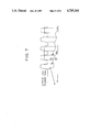
- FIG. 8 is an electrical circuit for memory back-up.
- FIG. 9 is a flow chart illustrating memory back-up monitor routine.
- FIG. 10 is a timing chart illustrating the function of the electrical to circuit shown in FIG. 8.
- air is sucked in an engine 11 through an air cleaner 12, an intake duct 13, a throttle chamber 14 and an intake manifold 15 and an exhaust gas is discharged through an exhaust manifold 16, an exhaust duct 17, a ternary catalyst 18 and a muffler 19.
- An air flow meter 21 is arranged in the intake duct 13 to put out a signal S1 of a flow quantity Q of intake air in the engine.
- the air flow meter 21 may be a hot wire type air flow meter.
- a primary side throttle valve 22 interconnected with an accelerator pedal (not shown) and a secondary side throttle valve 23 are arranged to control the intake air flow quantity Q.
- a throttle sensor 24 of the variable resistor type is attached to a throttle shaft of the primary side throttle valve 22 to put out an electric current signal S2 corresponding to a change of the electric resistance corresponding to the turning angle, that is, the opening degree, of the throttle valve 22.
- An idle switch which is turned on when the throttle valve 22 is fully closed is mounted on the throttle sensor 24.
- a fuel injection valve 25 mounted on the intake manifold 15 or an intake port of the engine 11 is an electromagnetic fuel injection valve which is opened on actuation through a solenoid and is closed on deenergization. Namely, the valve 25 is actuated and opened through the solenoid by a driving pulse signal C1 to inject and supply into the engine the fuel fed under pressure from a fuel pump (not shown).
- An O 2 sensor 26 acting as a means for detecting the concentration of an exhaust component is arranged in the exhaust manifold 16.
- the O 2 sensor 26 is a known sensor which puts out a voltage signal S3 corresponding to the ratio of the oxygen concentration in the exhaust gas to air and the electromotive force of which is abruptly changed when an air-fuel mixture is burnt at the theoretical air-fuel ratio (see FIG. 7). Accordingly, the O 2 sensor is a means for detecting the air-fuel ratio of the air-fuel mixture.
- the ternary catalyst 18 is a catalystic device for oxidizing or reducing CO, HC and NOx in the exhaust gas component at a high efficiency at an air-fuel ratio close to the theoretical air-fuel ratio of the air-fuel mixture to convert them to harmless substances.
- the means for detecting the driving state of the engine which puts out these detection signals to the control unit 100, comprises, in addition to the above-mentioned members, a crank angle sensor 31, a neutral switch 33 mounted on a transmission 32, a car speed sensor 35 mounted on a speed meter 34 of a car, and a water temperature sensor 37 for detecting the temperature of cooling water in a water jacket 36 for cooling the engine or cooling water in a thermostat housing of the cooling water circulation system.
- the crank angle sensor 31 is arranged to detect a rotation speed N of the engine and a crank angle (piston position), and a signal disc plate 52 is mounted on a crank pulley 51 and a crank angle sensor 31 puts out a reference signal S4 by, for example, every 180° in the crank angle in case of a 4-cylinder engine or by every 120° in the crank angle to case of a 6-cylinder engine and a position signal S5 by, for example, every 1° in the crank angle according to teeth formed on the periphery of the plate 52.
- the neutral switch 33 detects this and puts out a signal 56.
- the car speed sensor 35 detects the car speed and puts out a car speed signal S7.
- the water temperature sensor 37 puts out a voltage signal S8 changing according to the change of the temperature of cooling water corresponding to the temperature of the engine.
- the means for detecting the driving state of the engine further comprises an ignition switch 41 and a start switch 42.
- the ignition switch 41 is a switch for applying a voltage of a battery 43 to an ignition device and putting out an on-off signal S9 to the control unit 100.
- the start switch 42 is a switch which is turned on when a starter motor is driven to start the engine and which puts out an on-off signal S10. The terminal voltage of the battery 43 is put out to the control unit 100 by a signal S11.
- the detection signals S1 through S11 emitted from the respective elements of the means for detecting the driving state of the engine are put into the control unit 100 where the operation processing is carried out to put out a signal C1 of an optimum injection pulse width to the fuel injection valve and obtain a fuel injection quantity giving an optimum air-fuel ratio.
- the control unit 100 comprises CPU 101, P-ROM 102, CMOS-RAM 103 for the learning control of the air-fuel ratio and an address decoder 104, as shown in FIG. 3.
- a back-up power source circuit is used for RAM 103 to retain the content of the memory after the ignition switch 41 has been turned off.
- analogue input signals to be put in CPU 101 for the control of the fuel injection quantity there can be mentioned the signal S1 of the intake air flow quantity Q from the air flow meter 21, the throttle opening degree signal S2 from the throttle sensor 24, the water temperature signal S8 from the water temperature sensor 37, the signal S3 of the oxygen concentration in the exhaust gas from the O 2 sensor 26 and the battery voltage signal S11.
- These signals are put in CPU 101 through an analogue input interface 110 and an A/D converter 111.
- the A/D converter 111 is controlled by CPU 101 through an A/D conversion timing controller 112.
- the idle switch signal S2 which is turned on when the throttle valve 22 is fully closed
- on-off signals S10 and S6 supplied from the start switch 42 and the neutral switch 33.
- the reference signal S4 and position signal S5 from the crank angle sensor 31 are put in CPU 101 through a one-shot multichip circuit 118.
- the car speed signal S7 from the car speed sensor 35 is put in CPU 101 through a wave shaping circuit 120.
- the output signal from CPU 101(driving pulse signal to the fuel injection valve 25) is supplied to the fuel injection valve 25 through a current wave control circuit 121.
- CPU 101 controls the fuel injection quantity by performing input output operations and computing processings according to a program(stored in ROM 102)based on a flow chart shown in FIG. 4.
- the functions of the basic control quantity (basic fuel injection quantity) setting means, the learning correction quantity (coefficient) retrieving means, the feedback correction quantity (coefficient) setting means, the control quantity (fuel injection quantity)computing means, the learning correction quantity (coefficient ) correcting means, the control means, the constant state detecting means, the learning correction quantity renewal means, the renewal number memory means, and mean deviation ratio setting means are exerted according to the above-mentioned program.
- step 3 from the rotation number N of the engine and the basic fuel injection quantity (load) Tp, which represent the driving state of the engine, the corresponding learning correction coefficient Kl is retrieved.
- This portion corresponds to the learning correction coefficient retrieving means.
- a map in which the engine rotation number N is plotted on the abscissa and the base fuel injection quantity Tp is plotted on the ordinate is divided into regions by about 8 ⁇ 8 lattices, and the learning correction coefficient Kl for each region is stored in memory means, RAM 103. Incidentally, before initiation of learning, all of the learning correction coefficients Kl are set at the initial value of 1.
- At step 4 at least one learning correction coefficient Kl retrieved at step 3 is judged abnormal at an engine key turned ON, the learning correction coefficients Kl in the whole engine driving regions are initialized as is shown in detail in FIG. 5 illustrating a sub-routine for intializing Kl.
- FIG. 5 when the engine key is turned on(at S21), the retrieved learning correction coefficient Kl in an engine driving region is compared with the upper most level Klmax at step 22 and with the lower most level Klmin at step 23. In case of Kl>Klmax or Kl ⁇ Klmin, all of learning correction coefficients Kl stored in whole engine driving regions are initialized at step 24.
- RAM memories
- the learning correction coefficients Kl stored in the neighboring engine driving regions are undergone to have quite different values each other.
- the monitoring learning correction coefficient Kl at step 4 is capable to eliminate the afore-described defects.
- the voltage correction value Ts is set based on the voltage of the battery 43.
- step 6 it is judged whether or not the condition is the ⁇ control condition.
- the routine goes to step 11 described below from step 6 in the state where the feedback correction coefficient ⁇ is clamped to the precedent value (or standard value of 1).
- the output voltage Vo2 of the O 2 sensor 26 is compared with the slice level voltage Vref corresponding to the theoretical air-fuel ratio and it is judged whether the air-fuel ratio is rich or lean, and the feedback correction coefficient ⁇ is set by integration control or proportional integration control.
- This portion corresponds to the feedback correction coefficient setting means. More specifically, in case of integration control, if by comparison at step 7, it is judged that the air-fuel ratio is rich (Vo2>Vref), the feedback correction coefficient ⁇ is set by reducing a predetermined integration portion (I) from the preceding value at step 8.
- the feedback correction coefficient ⁇ is set by adding the predetermined integration portion (I) to the preceding value.
- proportional integration control in addition to the above-mentioned control, at the time of rick-lean inversion, a predetermined proportional portion (P) larger than the integration proportion (I) is subtracted or added in the same direction as that of the intergration portion (I).
- step 10 the operation of the learning sub-routine shown in FIG. 6 is carried out, as described hereinafter.
- This portion corresponds to the control value computing means.
- the value retrieved at step 4 or the value corrected through the learning sub-routine shown in FIG. 6 is used as Kl.
- a driving pulse signal having the pulse width of this Ti is put out at a predetermined timing synchronously with the rotation of the engine and given to the fuel injection valve 25 through the current wave control circuit 121. This portion corresponds to the control means.
- step 31 it is judged whether or not the engine rotation number N and basic fuel injection quantity Tp which represent the driving state of the engine are in the same region as the preceding region. In case of "Yes”, at step 32 it is judged whether or not a flag F is set. If the flag F is not set, at step 33 it is judged whether or not the output of the O 2 sensor 26 is inverted, that is, whether or not the increase-decrease direction of the feedback correction coefficient ⁇ is inverted. This flow is repeated and at every inversion, the count value indicating the inversion frequency is increased by 1 at step 34, and when the count value becomes 2, the routine goes to step 26 from step 25 to set the flag F.
- this flag F is regarded as becoming constant driving state and is set.
- the routine goes to step 37 through step 32.
- the constant state is detected if (1) the driving state of the engine is in one of the sectioned regions and (2) the increase-decrease direction of the feedback correction coefficient ⁇ is inverted at least a predetermined number of times (at least 2 times).
- step 37 it is judged whether or not the output of the O 2 sensor 26 is inverted, that is, whether or not the increase-decrease direction of the feedback correction coefficient ⁇ is inverted, and this flow is repeated and when inversion is caused, at step 38 it is judged whether or not the inversion is the first inversion after judgement of the constant engine driving state, that is, whether or not the inversion is the third inversion in the same region.
- This portion corresponds to the constant state detecting means.
- the routine goes to steps 40 through 46, and learning is carried out based on data between the third inversion and the fourth inversion (see FIG. 7).
- the routine similarly goes to steps 40 through 46 and learning is carried out based on the preceding inversion and the present inversion.
- the stored ⁇ 1 and ⁇ 2 values are upper and lower peak values of ⁇ between the preceding inversion (for example, the third inversion) and the present inversion (for example, the fourth inversion).
- step 42 the learning correction coefficient K1 stored in correspondence to the present region is retrieved.
- the value retrieved at step 3 can be used.
- a data of renewal number of a learning correction coefficient stored in the present engine driving region is read.
- the data of renewal number has been stored in every engine driving region divided by engine driving parameters of the engine revolution number N and the basic fuel injection quantity Tp as same in case of the learning correction coefficient Kl. This portion corresponds to the renewal number memory means.
- M which decides a weighted mean value of the preceding learning correction coefficient and the present learning correction coefficient, is retrieved from a map on the ROM 102 in accordance with the retrieved renewal number of Kl under the same engine driving region and set.
- the portion of steps 44 and 45 corresponds to the mean deviation ratio setting means.
- the value of M may be set to 1.0 when the renewal number of Kl is 1 and to be increased in accordance with increasing of the renewal number of Kl.
- the preceding learning correction coefficient Kl ⁇ (old) is renewed by the newly operated learning correction coefficient Kl(new) under the same engine driving region.
- the step 45 corresponds to the learning correction quantity renewal means.
- step 46 the value of renewal number of Kl stored under the corresponding engine driving region is countered by 1 up increment.
- the portion of step 46 as well as RAM 103 correspond to the renewal number memory means.
- step 47 ⁇ 2 is substituted for ⁇ 1 for the next operation routine.
- the value of M can be changed according to the renewal number of the learning correction coefficiency Kl,i,e, the advancing degree of learning of Kl and this results in the learning advance speed of Kl in the engine driving region, where the number of occasion being capable to learn Kl is quite few, made faster. Further, even when the data of learning correction coefficient Kl or of the renewal number of Kl stored in RAM 103 is initialized by disconnecting the battery 20 with CPU 101 and RAM 103 and the the renewal mumber of Kl is reset to 0, the value of 1/M can be automatically increased. This effects a rapidly relearning of Kl.
- the following method shows to forcibly clear the learning correction coefficient in RAM 103 and the data of the number of renewal after the battery 20 has been disconnected.
- an electric source is supplied to CPU 101 and ROM 102 from the battery through an engine key switch 21 and stabilizer regulator 61.
- the power source is supplied from the stabilizer regulator 61 through the diode 62, and when the engine key switch is off, the power source is supplied from a back-up power circuit 65 is a flip-flop a reset (R) terminal of which is connected with a power source terminal of RAM 103.
- An out put (Q) terminal of the flip-flop us connected with a port A of CPU 101 and a port B of CPU 101 is connected with a set (S) terminal of the flip-flop 65.
- CPU 101 decides whether or not the back-up of memory has been properly carried out at turning-on of the engine key switch 21, and if not, suitable procedures are taken.
- step 61 whether the in-put (namely, the output of the flip-flop 65) of the port A of CPU 101 is one or zero is decided. In case of decided as one, which is determined to be normal, this routine is finished. In case of decided as zero, which is determined to be abnormal, it advances to the next step 62.
- step 62 all the data in RAM 103 are returned to the initialized values. That is, all the data of the learning correction coefficient Kl are set to be one, and all the data of the renewal number are set to be zero. Next, it advances to the step 63.
- step 63 the out-put of one emits from the port B of CPU 101, the flip-flop 65 is reset and the out-put is returned to one.
- the memory is decided to be normally backed up since the input of the port A (namely, the output of the flip-flop 65) is one when the engine key switch is turned on, the data in RAM 103 is kept being used.
- the learning control apparatus for the air-fuel ratio has been described so far, but the present invention can be naturally applied to a learning control apparatus for idle rotation number.
- the basic control amount ISCtw is determined based on the engine cooling water temperature
- the learning correction quantity ISCle is retrieved from the water temperature
- the feed-back correction quantity ISC fb is determined based on the comparison between the aimed idle rotation number Ns determined based on the water temperature and the actual idle rotation number.
- the control quantity ISCdy to an idle control value 10 is operated by the following equation (1) and learning is executed according to the following equation (2) in a normal state.
- the mean value ⁇ ISCfb of deviations from the standard value of the feed-back correction amount ISCfb is added by the prescribed ratio (1/M)
- the value M may be set according to the renewal rotation number.
- Aforementioned idle control valve is provided with a opening-valve coil and a closing-valve coil and so constituted that pulse signals which have been decided are sent to these coils and the opening degree is adjusted according to the duty ratio of the pulse signal.
- Aforementioned ISCdy stands for the time ratio (% ) when the opening valve coil is on.
- the speed of learning advance can be quickened in the region where learning occasions are few by changing the weighted value at the renewal of the learning correction quantity corresponding to the advancing degree of learning. Moreover, when the data of learning correction quantity is cleared by disconnecting of the battery and the like, rapid re-learning can be possible.
Abstract
Description
Ti=Tp×COEF×α+Ts and Tp=K×Q/N
COEF=1+Ktw+Kas+Kai+Kmr+Ketc
Ti=Tp×COEF×Kl×α+Ts (1)
Kl(new)←Kl(old)+Δα/M
Kl(new)←Kl(old)+Δα/M
ISCdy=ISC+w+ISCle+ISC+b (1)
ISCle(new)←ISCle+ΔISCfb/M (2)
Claims (12)
Ti=Tp×COEF×Kl×α+Ts
Applications Claiming Priority (4)
| Application Number | Priority Date | Filing Date | Title |
|---|---|---|---|
| JP60-171223 | 1985-08-05 | ||
| JP17122385A JPS6232259A (en) | 1985-08-05 | 1985-08-05 | Monitor of learning controller for internal combustion engine |
| JP60-208913 | 1985-09-24 | ||
| JP20891385A JPS6270641A (en) | 1985-09-24 | 1985-09-24 | Learning control device for internal combustion engine |
Publications (1)
| Publication Number | Publication Date |
|---|---|
| US4715344A true US4715344A (en) | 1987-12-29 |
Family
ID=26494019
Family Applications (1)
| Application Number | Title | Priority Date | Filing Date |
|---|---|---|---|
| US06/891,967 Expired - Lifetime US4715344A (en) | 1985-08-05 | 1986-08-01 | Learning and control apparatus for electronically controlled internal combustion engine |
Country Status (1)
| Country | Link |
|---|---|
| US (1) | US4715344A (en) |
Cited By (32)
| Publication number | Priority date | Publication date | Assignee | Title |
|---|---|---|---|---|
| US4796589A (en) * | 1987-03-31 | 1989-01-10 | Honda Giken Kogyo K.K. (Honda Motor Co., Ltd. In English) | Air-fuel ratio feedback control method for internal combustion engines |
| US4800857A (en) * | 1987-01-21 | 1989-01-31 | Nippon Denshi Kiki Co., Ltd. | Apparatus for learn-controlling air-fuel ratio for internal combustion engine |
| DE3835766A1 (en) * | 1987-10-20 | 1989-05-18 | Japan Electronic Control Syst | ELECTRONIC, ADAPTABLE CONTROL UNIT FOR A COMBUSTION ENGINE |
| US4841933A (en) * | 1987-01-14 | 1989-06-27 | Lucas Industries Public Limited Company | Adaptive control system for an internal combustion engine |
| US4844041A (en) * | 1987-03-05 | 1989-07-04 | Honda Giken Kogyo Kabushiki Kaisha | Method of controlling the air/fuel ratio for an internal combustion engine mounted on a vehicle |
| US4850326A (en) * | 1986-10-21 | 1989-07-25 | Japan Electronic Control Systems, Co., Ltd. | Apparatus for learning and controlling air/fuel ratio in internal combustion engine |
| US4854287A (en) * | 1986-10-21 | 1989-08-08 | Japan Electronic Control Systems Co., Ltd. | Apparatus for learning and controlling air/fuel ratio in internal combustion engine |
| US4870938A (en) * | 1987-09-11 | 1989-10-03 | Japan Electronic Control Systems Co., Ltd. | Electronic air-fuel ratio control apparatus in internal combustion engine |
| WO1989009331A1 (en) * | 1988-04-02 | 1989-10-05 | Robert Bosch Gmbh | Learning control process for an internal combustion engine and device therefor |
| US4878473A (en) * | 1987-09-30 | 1989-11-07 | Japan Electronic Control Systems Co. Ltd. | Internal combustion engine with electronic air-fuel ratio control apparatus |
| US4893600A (en) * | 1987-06-27 | 1990-01-16 | Lucas Industries Plc | Adaptive control for an internal combustion engine |
| US4896639A (en) * | 1986-12-09 | 1990-01-30 | Lucas Industries Public Limited Company | Method and apparatus for engine control and combustion quality detection |
| US4899280A (en) * | 1987-04-08 | 1990-02-06 | Hitachi, Ltd. | Adaptive system for controlling an engine according to conditions categorized by driver's intent |
| US4899282A (en) * | 1985-07-23 | 1990-02-06 | Lucas Industries Public Limited Company | Method and apparatus for controlling an internal combustion engine |
| US4901240A (en) * | 1986-02-01 | 1990-02-13 | Robert Bosch Gmbh | Method and apparatus for controlling the operating characteristic quantities of an internal combustion engine |
| US4903670A (en) * | 1987-02-25 | 1990-02-27 | Audi Ag | Control device for a diesel internal combustion engine |
| US4915080A (en) * | 1987-09-22 | 1990-04-10 | Japan Electronic Control Systems Co., Ltd. | Electronic air-fuel ratio control apparatus in internal combustion engine |
| US4924836A (en) * | 1987-06-26 | 1990-05-15 | Nissan Motor Company, Limited | Air/fuel ratio control system for internal combustion engine with correction coefficient learning feature |
| US4926826A (en) * | 1987-08-31 | 1990-05-22 | Japan Electronic Control Systems Co., Ltd. | Electric air-fuel ratio control apparatus for use in internal combustion engine |
| US5001645A (en) * | 1987-01-14 | 1991-03-19 | Lucas Industries Public Limited Company | Adaptive control system for an engine |
| US5003955A (en) * | 1989-01-20 | 1991-04-02 | Nippondenso Co., Ltd. | Method of controlling air-fuel ratio |
| US5070847A (en) * | 1990-02-28 | 1991-12-10 | Honda Giken Kogyo Kabushiki Kaisha | Method of detecting abnormality in fuel supply systems of internal combustion engines |
| EP0460892A2 (en) * | 1990-06-04 | 1991-12-11 | Hitachi, Ltd. | A control device for controlling a controlled apparatus, and a control method therefor |
| EP0481492A2 (en) * | 1990-10-17 | 1992-04-22 | Omron Corporation | Feedback control apparatus and method |
| US5148791A (en) * | 1990-09-19 | 1992-09-22 | Hitachi, Ltd. | Method of electronic engine control for internal combustion engine having a plurality of cylinders |
| US5251437A (en) * | 1990-09-04 | 1993-10-12 | Japan Electronic Control Systems Co., Ltd. | Method and system for controlling air/fuel ratio for internal combustion engine |
| US5522034A (en) * | 1993-08-20 | 1996-05-28 | Nippondenso Co., Ltd. | Battery disconnection detecting apparatus |
| US6016787A (en) * | 1997-07-04 | 2000-01-25 | Unisia Jecs Corporation | Idle rotation speed learning control apparatus and method of engine |
| EP0997628A2 (en) * | 1998-10-28 | 2000-05-03 | C.R.F. Società Consortile per Azioni | Method of controlling injection of an internal combustion engine as a function of fuel quality |
| US6076037A (en) * | 1997-10-27 | 2000-06-13 | Keihin Corporation | Engine control system |
| US20050092300A1 (en) * | 2003-11-05 | 2005-05-05 | Denso Corporation | Injection control system of internal combustion engine |
| CN110872998A (en) * | 2018-09-03 | 2020-03-10 | 现代自动车株式会社 | Method for verifying CVVD position learning result and CVVD system for verifying CVVD position learning result |
Citations (11)
| Publication number | Priority date | Publication date | Assignee | Title |
|---|---|---|---|---|
| US3483851A (en) * | 1966-11-25 | 1969-12-16 | Bosch Gmbh Robert | Fuel injection control system |
| US3750632A (en) * | 1970-03-26 | 1973-08-07 | Bosch Gmbh Robert | Electronic control for the air-fuel mixture and for the ignition of an internal combustion engine |
| US4284050A (en) * | 1978-10-25 | 1981-08-18 | Robert Bosch Gmbh | Apparatus for controlling the mixture composition in an internal combustion engine |
| JPS59203829A (en) * | 1983-05-02 | 1984-11-19 | Japan Electronic Control Syst Co Ltd | Air-fuel ratio learning control apparatus for electronically controlled fuel injection type internal-combustion engine |
| JPS59203828A (en) * | 1983-05-02 | 1984-11-19 | Japan Electronic Control Syst Co Ltd | Air-fuel ratio learning control apparatus for electronically controlled fuel injection type internal-combustion engine |
| JPS59211738A (en) * | 1983-05-18 | 1984-11-30 | Japan Electronic Control Syst Co Ltd | Learning control device of idling rotation number of internal-combustion engine |
| JPS59211742A (en) * | 1983-05-18 | 1984-11-30 | Japan Electronic Control Syst Co Ltd | Memory back-up monitoring device of learning control unit of internal-combustion engine for car |
| JPS6090944A (en) * | 1983-10-24 | 1985-05-22 | Japan Electronic Control Syst Co Ltd | Air-fuel ratio learning control apparatus for electronically controlled fuel injection type internal-combustion engine |
| JPS6093143A (en) * | 1983-10-28 | 1985-05-24 | Japan Electronic Control Syst Co Ltd | Control device of idle speed in internal-combustion engine |
| US4552115A (en) * | 1983-04-14 | 1985-11-12 | Mazda Motor Corporation | Air-fuel ratio control means for internal combustion engines |
| US4615319A (en) * | 1983-05-02 | 1986-10-07 | Japan Electronic Control Systems Co., Ltd. | Apparatus for learning control of air-fuel ratio of airfuel mixture in electronically controlled fuel injection type internal combustion engine |
-
1986
- 1986-08-01 US US06/891,967 patent/US4715344A/en not_active Expired - Lifetime
Patent Citations (11)
| Publication number | Priority date | Publication date | Assignee | Title |
|---|---|---|---|---|
| US3483851A (en) * | 1966-11-25 | 1969-12-16 | Bosch Gmbh Robert | Fuel injection control system |
| US3750632A (en) * | 1970-03-26 | 1973-08-07 | Bosch Gmbh Robert | Electronic control for the air-fuel mixture and for the ignition of an internal combustion engine |
| US4284050A (en) * | 1978-10-25 | 1981-08-18 | Robert Bosch Gmbh | Apparatus for controlling the mixture composition in an internal combustion engine |
| US4552115A (en) * | 1983-04-14 | 1985-11-12 | Mazda Motor Corporation | Air-fuel ratio control means for internal combustion engines |
| JPS59203829A (en) * | 1983-05-02 | 1984-11-19 | Japan Electronic Control Syst Co Ltd | Air-fuel ratio learning control apparatus for electronically controlled fuel injection type internal-combustion engine |
| JPS59203828A (en) * | 1983-05-02 | 1984-11-19 | Japan Electronic Control Syst Co Ltd | Air-fuel ratio learning control apparatus for electronically controlled fuel injection type internal-combustion engine |
| US4615319A (en) * | 1983-05-02 | 1986-10-07 | Japan Electronic Control Systems Co., Ltd. | Apparatus for learning control of air-fuel ratio of airfuel mixture in electronically controlled fuel injection type internal combustion engine |
| JPS59211738A (en) * | 1983-05-18 | 1984-11-30 | Japan Electronic Control Syst Co Ltd | Learning control device of idling rotation number of internal-combustion engine |
| JPS59211742A (en) * | 1983-05-18 | 1984-11-30 | Japan Electronic Control Syst Co Ltd | Memory back-up monitoring device of learning control unit of internal-combustion engine for car |
| JPS6090944A (en) * | 1983-10-24 | 1985-05-22 | Japan Electronic Control Syst Co Ltd | Air-fuel ratio learning control apparatus for electronically controlled fuel injection type internal-combustion engine |
| JPS6093143A (en) * | 1983-10-28 | 1985-05-24 | Japan Electronic Control Syst Co Ltd | Control device of idle speed in internal-combustion engine |
Cited By (40)
| Publication number | Priority date | Publication date | Assignee | Title |
|---|---|---|---|---|
| US4899282A (en) * | 1985-07-23 | 1990-02-06 | Lucas Industries Public Limited Company | Method and apparatus for controlling an internal combustion engine |
| US4901240A (en) * | 1986-02-01 | 1990-02-13 | Robert Bosch Gmbh | Method and apparatus for controlling the operating characteristic quantities of an internal combustion engine |
| US4850326A (en) * | 1986-10-21 | 1989-07-25 | Japan Electronic Control Systems, Co., Ltd. | Apparatus for learning and controlling air/fuel ratio in internal combustion engine |
| US4854287A (en) * | 1986-10-21 | 1989-08-08 | Japan Electronic Control Systems Co., Ltd. | Apparatus for learning and controlling air/fuel ratio in internal combustion engine |
| US4896639A (en) * | 1986-12-09 | 1990-01-30 | Lucas Industries Public Limited Company | Method and apparatus for engine control and combustion quality detection |
| US5001645A (en) * | 1987-01-14 | 1991-03-19 | Lucas Industries Public Limited Company | Adaptive control system for an engine |
| US4841933A (en) * | 1987-01-14 | 1989-06-27 | Lucas Industries Public Limited Company | Adaptive control system for an internal combustion engine |
| US4800857A (en) * | 1987-01-21 | 1989-01-31 | Nippon Denshi Kiki Co., Ltd. | Apparatus for learn-controlling air-fuel ratio for internal combustion engine |
| US4903670A (en) * | 1987-02-25 | 1990-02-27 | Audi Ag | Control device for a diesel internal combustion engine |
| US4844041A (en) * | 1987-03-05 | 1989-07-04 | Honda Giken Kogyo Kabushiki Kaisha | Method of controlling the air/fuel ratio for an internal combustion engine mounted on a vehicle |
| US4796589A (en) * | 1987-03-31 | 1989-01-10 | Honda Giken Kogyo K.K. (Honda Motor Co., Ltd. In English) | Air-fuel ratio feedback control method for internal combustion engines |
| US4899280A (en) * | 1987-04-08 | 1990-02-06 | Hitachi, Ltd. | Adaptive system for controlling an engine according to conditions categorized by driver's intent |
| US5099429A (en) * | 1987-04-08 | 1992-03-24 | Hitachi, Ltd. | Adaptive system for controlling an engine according to conditions categorized by driver's intent |
| US4924836A (en) * | 1987-06-26 | 1990-05-15 | Nissan Motor Company, Limited | Air/fuel ratio control system for internal combustion engine with correction coefficient learning feature |
| US4893600A (en) * | 1987-06-27 | 1990-01-16 | Lucas Industries Plc | Adaptive control for an internal combustion engine |
| US4926826A (en) * | 1987-08-31 | 1990-05-22 | Japan Electronic Control Systems Co., Ltd. | Electric air-fuel ratio control apparatus for use in internal combustion engine |
| US4870938A (en) * | 1987-09-11 | 1989-10-03 | Japan Electronic Control Systems Co., Ltd. | Electronic air-fuel ratio control apparatus in internal combustion engine |
| US4915080A (en) * | 1987-09-22 | 1990-04-10 | Japan Electronic Control Systems Co., Ltd. | Electronic air-fuel ratio control apparatus in internal combustion engine |
| US4878473A (en) * | 1987-09-30 | 1989-11-07 | Japan Electronic Control Systems Co. Ltd. | Internal combustion engine with electronic air-fuel ratio control apparatus |
| US4881505A (en) * | 1987-10-20 | 1989-11-21 | Japan Electronic Control Systems Co., Ltd. | Electronic learning control apparatus for internal combustion engine |
| DE3835766A1 (en) * | 1987-10-20 | 1989-05-18 | Japan Electronic Control Syst | ELECTRONIC, ADAPTABLE CONTROL UNIT FOR A COMBUSTION ENGINE |
| WO1989009331A1 (en) * | 1988-04-02 | 1989-10-05 | Robert Bosch Gmbh | Learning control process for an internal combustion engine and device therefor |
| US5023794A (en) * | 1988-04-02 | 1991-06-11 | Robert Bosch Gmbh | Method and apparatus for an internal combustion engine with learning closed-loop control |
| US5003955A (en) * | 1989-01-20 | 1991-04-02 | Nippondenso Co., Ltd. | Method of controlling air-fuel ratio |
| US5070847A (en) * | 1990-02-28 | 1991-12-10 | Honda Giken Kogyo Kabushiki Kaisha | Method of detecting abnormality in fuel supply systems of internal combustion engines |
| EP0460892A2 (en) * | 1990-06-04 | 1991-12-11 | Hitachi, Ltd. | A control device for controlling a controlled apparatus, and a control method therefor |
| US5430642A (en) * | 1990-06-04 | 1995-07-04 | Hitachi, Ltd. | Control device for controlling a controlled apparatus, and a control method therefor |
| EP0460892A3 (en) * | 1990-06-04 | 1992-09-16 | Hitachi, Ltd. | A control device for controlling a controlled apparatus, and a control method therefor |
| US5251437A (en) * | 1990-09-04 | 1993-10-12 | Japan Electronic Control Systems Co., Ltd. | Method and system for controlling air/fuel ratio for internal combustion engine |
| US5148791A (en) * | 1990-09-19 | 1992-09-22 | Hitachi, Ltd. | Method of electronic engine control for internal combustion engine having a plurality of cylinders |
| EP0481492A3 (en) * | 1990-10-17 | 1993-04-28 | Omron Corporation | Feedback control apparatus and method |
| EP0481492A2 (en) * | 1990-10-17 | 1992-04-22 | Omron Corporation | Feedback control apparatus and method |
| US5522034A (en) * | 1993-08-20 | 1996-05-28 | Nippondenso Co., Ltd. | Battery disconnection detecting apparatus |
| US6016787A (en) * | 1997-07-04 | 2000-01-25 | Unisia Jecs Corporation | Idle rotation speed learning control apparatus and method of engine |
| US6076037A (en) * | 1997-10-27 | 2000-06-13 | Keihin Corporation | Engine control system |
| EP0997628A2 (en) * | 1998-10-28 | 2000-05-03 | C.R.F. Società Consortile per Azioni | Method of controlling injection of an internal combustion engine as a function of fuel quality |
| EP0997628B1 (en) * | 1998-10-28 | 2004-07-14 | C.R.F. Società Consortile per Azioni | Method of controlling injection of an internal combustion engine as a function of fuel quality |
| US20050092300A1 (en) * | 2003-11-05 | 2005-05-05 | Denso Corporation | Injection control system of internal combustion engine |
| US7032582B2 (en) * | 2003-11-05 | 2006-04-25 | Denso Corporation | Injection control system of internal combustion engine |
| CN110872998A (en) * | 2018-09-03 | 2020-03-10 | 现代自动车株式会社 | Method for verifying CVVD position learning result and CVVD system for verifying CVVD position learning result |
Similar Documents
| Publication | Publication Date | Title |
|---|---|---|
| US4715344A (en) | Learning and control apparatus for electronically controlled internal combustion engine | |
| US4729359A (en) | Learning and control apparatus for electronically controlled internal combustion engine | |
| US4655188A (en) | Apparatus for learning control of air-fuel ratio of air-fuel mixture in electronically controlled fuel injection type internal combustion engine | |
| US4615319A (en) | Apparatus for learning control of air-fuel ratio of airfuel mixture in electronically controlled fuel injection type internal combustion engine | |
| US5875756A (en) | Ignition timing control system for in-cylinder injection internal combustion engine | |
| US4649878A (en) | Method of feedback-controlling idling speed of internal combustion engine | |
| US4502442A (en) | Optimum ignition and A/F control for internal-combustion engine | |
| US5662084A (en) | Engine idling speed control apparatus | |
| US7472686B2 (en) | Control apparatus and method and engine control unit for internal combustion engine | |
| US4633093A (en) | Method of feedback-controlling idling speed of internal combustion engine | |
| US5884477A (en) | Fuel supply control system for internal combustion engines | |
| US4926826A (en) | Electric air-fuel ratio control apparatus for use in internal combustion engine | |
| US5099817A (en) | Process and apparatus for learning and controlling air/fuel ratio in internal combustion engine | |
| US4763627A (en) | Learning and control apparatus for electronically controlled internal combustion engine | |
| US4466411A (en) | Air/fuel ratio feedback control method for internal combustion engines | |
| EP0110312B1 (en) | Engine control method | |
| US5983155A (en) | Method and arrangement for controlling an internal combustion engine | |
| EP0216071B1 (en) | Method and device for controlling the idle speed of internal combustion engines | |
| US4739740A (en) | Internal combustion engine air-fuel ratio feedback control method functioning to compensate for aging change in output characteristic of exhaust gas concentration sensor | |
| US5722368A (en) | Method and apparatus for adjusting the intake air flow rate of an internal combustion engine | |
| US5115781A (en) | Air-fuel ratio controller for internal combustion engine | |
| US4751906A (en) | Air-fuel ratio control method for internal combustion engines | |
| US4850326A (en) | Apparatus for learning and controlling air/fuel ratio in internal combustion engine | |
| US4708109A (en) | Apparatus for controlling an idle speed of an internal combustion engine | |
| EP0889216B1 (en) | Idle rotation speed learning control apparatus and method of engine |
Legal Events
| Date | Code | Title | Description |
|---|---|---|---|
| AS | Assignment |
Owner name: JAPAN ELECTRONIC CONTROL SYSTEMS CO., LTD. Free format text: ASSIGNMENT OF ASSIGNORS INTEREST.;ASSIGNOR:TOMISAWA, NAOKI;REEL/FRAME:004586/0807 Effective date: 19860715 |
|
| STCF | Information on status: patent grant |
Free format text: PATENTED CASE |
|
| FEPP | Fee payment procedure |
Free format text: PAYOR NUMBER ASSIGNED (ORIGINAL EVENT CODE: ASPN); ENTITY STATUS OF PATENT OWNER: LARGE ENTITY |
|
| FPAY | Fee payment |
Year of fee payment: 4 |
|
| FEPP | Fee payment procedure |
Free format text: PAYOR NUMBER ASSIGNED (ORIGINAL EVENT CODE: ASPN); ENTITY STATUS OF PATENT OWNER: LARGE ENTITY |
|
| FPAY | Fee payment |
Year of fee payment: 8 |
|
| FPAY | Fee payment |
Year of fee payment: 12 |
|
| AS | Assignment |
Owner name: HITACHI, LTD., JAPAN Free format text: MERGER;ASSIGNOR:HITACHI UNISIA AUTOMOTIVE, LTD.;REEL/FRAME:016283/0114 Effective date: 20040927 |
|
| AS | Assignment |
Owner name: UNISIA JECS CORPORATION, JAPAN Free format text: MERGER;ASSIGNOR:JAPAN ELECTRONIC CONTROL SYSTEMS CO. LTD.;REEL/FRAME:016651/0683 Effective date: 19970721 |