US4714853A - Low profile electric motor - Google Patents
Low profile electric motor Download PDFInfo
- Publication number
- US4714853A US4714853A US06/903,470 US90347086A US4714853A US 4714853 A US4714853 A US 4714853A US 90347086 A US90347086 A US 90347086A US 4714853 A US4714853 A US 4714853A
- Authority
- US
- United States
- Prior art keywords
- rotor
- pair
- poles
- stator
- pole pieces
- Prior art date
- Legal status (The legal status is an assumption and is not a legal conclusion. Google has not performed a legal analysis and makes no representation as to the accuracy of the status listed.)
- Expired - Lifetime
Links
- 230000004907 flux Effects 0.000 claims description 19
- 230000001360 synchronised effect Effects 0.000 claims description 8
- 230000005611 electricity Effects 0.000 abstract description 4
- 238000010276 construction Methods 0.000 description 9
- 230000013011 mating Effects 0.000 description 8
- 238000004519 manufacturing process Methods 0.000 description 3
- 239000000853 adhesive Substances 0.000 description 2
- 230000001070 adhesive effect Effects 0.000 description 2
- 230000014509 gene expression Effects 0.000 description 2
- 239000000463 material Substances 0.000 description 2
- 238000003466 welding Methods 0.000 description 2
- 238000004804 winding Methods 0.000 description 2
- XAGFODPZIPBFFR-UHFFFAOYSA-N aluminium Chemical compound [Al] XAGFODPZIPBFFR-UHFFFAOYSA-N 0.000 description 1
- 229910052782 aluminium Inorganic materials 0.000 description 1
- 239000010960 cold rolled steel Substances 0.000 description 1
- 230000003247 decreasing effect Effects 0.000 description 1
- 239000000696 magnetic material Substances 0.000 description 1
- 230000004048 modification Effects 0.000 description 1
- 238000012986 modification Methods 0.000 description 1
- 230000000717 retained effect Effects 0.000 description 1
- 239000007779 soft material Substances 0.000 description 1
- 239000007787 solid Substances 0.000 description 1
- 239000010935 stainless steel Substances 0.000 description 1
- 229910001220 stainless steel Inorganic materials 0.000 description 1
Images


Classifications
-
- H—ELECTRICITY
- H02—GENERATION; CONVERSION OR DISTRIBUTION OF ELECTRIC POWER
- H02K—DYNAMO-ELECTRIC MACHINES
- H02K21/00—Synchronous motors having permanent magnets; Synchronous generators having permanent magnets
- H02K21/12—Synchronous motors having permanent magnets; Synchronous generators having permanent magnets with stationary armatures and rotating magnets
- H02K21/125—Synchronous motors having permanent magnets; Synchronous generators having permanent magnets with stationary armatures and rotating magnets having an annular armature coil
-
- H—ELECTRICITY
- H02—GENERATION; CONVERSION OR DISTRIBUTION OF ELECTRIC POWER
- H02K—DYNAMO-ELECTRIC MACHINES
- H02K2201/00—Specific aspects not provided for in the other groups of this subclass relating to the magnetic circuits
- H02K2201/12—Transversal flux machines
Definitions
- This invention relates to electric rotating machines and more particularly to electric motors of the type in which the rotor of the motor turns in discrete increments or steps.
- alternating current synchronous and stepper motors which exhibit extremely rapid starting characteristics and are highly efficient. Included in this class are motors utilizing a permanent magnet rotor having a plurality of alternating poles and annular stators mounted side by side in tandem with a plurality or salient stator poles on their inner peripheries. The windings of each of the stators are independently energizable out of phase with one another so that the rotational direction of the motor can be controlled.
- motors of this class are satisfactory for many purposes, such motors have exhibited certain disadvantages.
- such motors are not readily adaptable for applications which require a motor having a very low profile, or a pancake-type construction, such as may be required of motors for computer disk drives or automobile electric windows.
- the thickness, and hence the weight, inertia and cost, of the permanent magnet rotor of prior art tandem stator motors may be as much as twice as great as magnetically required to develop full torque.
- such motors have a considerable amount of wasted space, making such motors undesirable where compact construction is needed.
- the machine includes an annular permanent magnetic rotor having rotor poles of alternating polarity around its circumference.
- An outer stator is included which comprises a first pair of pole pieces of annular configuration in opposed relationship with each other to form an annular space therebetween, each of the first pair of pole pieces being disposed around the outer periphery of the rotor.
- Each pole piece in the first pair includes on its inner periphery spaced-apart axially extending salient stator poles in magnetic flux relationship with the rotor poles, the stator poles of the respective pole pieces being interleaved with one another.
- An inner stator which comprises a second pair of pole pieces of annular configuration in opposed relationship with each other to form an annular space therebetween, each of the second pair of pole pieces being disposed within the inner periphery of the rotor.
- Each pole piece in the second pair includes on its outer periphery spaced-apart axially extending salient stator poles in magnetic flux relationship with the rotor poles, with the stator poles of the respective pole pieces being interleaved with one another.
- First annular energizing means are provided surrounding the outer periphery of the rotor and disposed substantially entirely within the annular space between the first pair of stator pole pieces for producing a magnetic field in the salient stator poles of the first pair.
- a second annular energizing means is provided within the inner periphery of the rotor and disposed substantially entirely within the annular space between the second pair of stator pole pieces for producing a magnetic field in the salient stator poles of the second pair.
- Means for sequentially energizing said first and second energizing means to respectively produce the corresponding magnetic field with said fields in different phase relationship with each other is provided.
- FIG. 1 is a front perspective view of a stepper motor in accordance with an illustrative embodiment of the present invention.
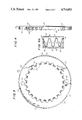
- FIG. 2 is a cut-away view of the motor taken along line 2--2 of FIG. 1.
- FIG. 3 is a plan view of one of the pair of cup-shaped annular pole pieces of the outer stator.
- FIG. 4 is an elevational view of the cup-shaped stator pole piece of FIG. 3.
- FIG. 4A is a sectional view taken along the line 4A--4A of FIG. 2 showing the interleaving of the stator poles of the pole pieces of FIG. 3 and FIG. 4, when assembled together as a pair to form the outer stator.
- FIG. 5 is a plan view of one of the pair of annular cup-shaped pole pieces of the inner stator.
- FIG. 6 is an elevational view of the cup-shaped stator pole piece FIG. 5.
- FIG. 7 is a plan view of the non-salient permanent magnet rotor.
- FIGS. 1, 2 and 7 an electric motor 10 constructed in accordance with a preferred embodiment of the present invention is illustrated.
- the motor 10 has an annular permanent magnet rotor 45 having a first set of non-salient rotor poles 40 of alternating polarity around its outer periphery and a corresponding second set of non-salient rotor poles 55 of opposite polarity around its inner periphery, each rotor pole 40 of the first set being in radial alignment with a rotor pole 55 of opposite polarity in the second set.
- Non-salient rotor poles are preferred because of decreased cost of such rotors over salient rotor poles or individual permanent magnets supported in an annular non-magnetic carrier.
- an annular rotor having salient rotor poles or individual permanent magnets supported in an annular non-magnetic carrier can also be used.
- the permanent magnet rotor has twenty-four non-salient north poles, and twenty-four non-salient south poles alternating around its outer periphery, for a total of 48 poles, and a like number around its inner periphery.
- the radially aligned poles on the inner and outer periphery of the rotor are preferably of opposite polarity. Although preferred, it is not necessary that the radially aligned poles on the inner and outer peripheries of the rotor be of opposite polarity, since a rotor constructed with radially aligned poles of like polarity with also work in the invention.
- the inner and outer stators must, of course, be angularly displaced so that their poles will be in appropriate alignment with the poles of the rotor.
- the total number of rotor poles can, of course, be any even number.
- the rotor is supported by a wheel 65 comprising a hub 70, spokes or ribs 75, and an outer rotor ring 80.
- a solid wheel can, of course, be used interchangeably, and this is actually preferred due to the low cost and ease of fabrication.
- the rotor is constructed with an annular slot 60 on its front face which is adapted to receive the rotor ring 80.
- the rotor ring is preferably made of a lightweight, non-magnetic material such as aluminum to minimize weight and magnetic flux leakage and may be attached to the rotor by interference fit, adhesives or other convenient means.
- the purpose of the rotor ring 80 and mating slot 60 is to provide an inexpensive and secure connection of the wheel 65 to the rotor 45.
- the rotor ring 80 can, of course, be omitted if the wheel is otherwise secured to the rotor 45 directly, such as by screws or adhesive.
- the hub 70 of wheel 65 is connected to driving shaft 85, which is constructed of strong material such as stainless steel.
- Shaft 85 is supported by ball bearings 90 retained in a bearing block 95 to permit rotation.
- the bearing block is, in turn, attached to base plate 100 by any suitable means, such as by welding or bolting.
- the motor 10 has an outer stator 15 of annular configuration disposed generally concentrically around the outer periphery of the rotor 45.
- the outer stator 15 comprises a pair of cup-shaped pole pieces 20 and 20'. Pole pieces 20 and 20' are mated together in an opposed relationship to form an annular space between them to receive energizing means comprising an annular wound coil of wire 50. This coil of wire 50 is disposed substantially entirely within the annular space, as shown in cross-section in FIG. 2.
- pole pieces 20 and 20' are identical, thus achieving economies in manufacturing and spare parts inventories. Pole pieces 20 and 20' are identical in this preferred embodiment.
- pole pieces 20 and 20' are identical, only pole piece 20 is shown in these figures.
- pole piece 20 has alternating mating teeth 25 and slots 27 around its outer periphery. These mating teeth and slots are preferably generally square cut and of the same height and width for ease of manufacturing and assembly, and so that identical pole pieces will mate together tooth-in-slot with the poles 35 and 35' properly interleaved.
- the teeth 25 and slots 27 preferably mesh as tightly together as possible so as to make a complete magnetic circuit around the outer periphery of the stator with a minimum of flux leakage across the tooth joints.
- the pole pieces 20 should be formed of a magnetically soft material such as ASTM 1008 cold rolled steel.
- the axial thickness of the stator 15, with pole pieces 20 and 20' mated together is preferably less than the axial thickness of the rotor 45.
- Inner stator 115 is generally similar to outer stator 15 in construction and function, except that poles 125 and valleys 127 are on its outer periphery, the mating teeth 135 and slots 137 are on its inner periphery. Furthermore, the inner stator 115 is also disposed generally concentrically with the rotor 45, but on the inner periphery of rotor 45, between the bearing block 95 and the rotor 45. As with the outer stator 15, the inner stator 115 comprises a pair of pole pieces 120 and 120', preferably identical, which have interleaved salient poles 125 and preferably square cut mating teeth 135.
- the number of poles on each inner pole piece (120 and 120') is preferably the same as the number of poles on each outer pole piece.
- Each pole piece 120 and 120' has index holes 130 on opposite sides of the centerline of the pole piece.
- the poles of mating pole pieces interleave in the same way as the poles of the outer stator pole pieces (i.e. as shown in FIG. 4A), and the preferred material of construction is the same.
- the axial thickness of the inner stator 115 is also preferably less than the axial thickness of the rotor 45.
- the inner stator 115 is mounted to the base place by any convenient means, such as welding or bolting, with its poles preferably 90 electrical degrees offset from the corresponding poles of the outer stator 15. As can be seen in FIG. 2, the inner stator 115 takes up virtually all the space between the inner periphery of the rotor 45 and the bearing block 95, thus achieving a very compact construction with an absolute minimum of wasted space. Because the rotor 45 is flanked on both its inner and outer peripheries by stators, rather than only on its outer periphery as with a tandem stator configuration, the motor has been found to have increased torque output for the same weight rotor, as compared with motors of the tandem configuration.
- energizing means comprising an annularly wound coil 150, is disposed substantially entirely within the annular space formed between the inner pair of stator pole pieces 120 and 120' comprising the inner stator 115.
- each of the coils are sequentially energized, preferably by separate sources of electrical current 90 electrical degrees out of phase with one another, so that the stepping angle will be uniform and so that the direction of rotation of the rotor can be controlled.
- the rotor At rest, with neither inner nor outer stators energized, the rotor will reach a stable intermediate position.
- the outer coil When, for example, the outer coil is energized with current in the clockwise direction (facing the front end of the motor), the salient stator poles of the outer stator will become magnetized alternatingly north and south, and the rotor will advance one step of 3.75 degrees (360 degrees divided by 2N, where 2 is the number of electrical phases and N is the number of poles on the rotor, which is 48 for the motor 10 shown in the figures), aligning itself magnetically with the salient stator poles 35 and 35' of the outer stator 15.
- clockwise energization of the inner stator coil commences, which will advance the rotor one more 3.75 degree step.
- the direction of current in the outer stator coil may then be reversed, which will advance the rotor to the next step, and so on.
- Such a motor can be constructed by adding a third stator in tandem with either the inner or outer stator, with the axial thickness of the rotor increased to accomodate the tandem stator, or the tandem stators made axially thinner and radially thicker.
- a three phase motor can also be constructed by adding another outer rotor concentrically with the inner rotor, around the outside of the outer stator, and a third stator added concentrically around this outer rotor. Four, or any number of phases of electricity can be accommodated in the same manner.
Landscapes
- Engineering & Computer Science (AREA)
- Power Engineering (AREA)
- Permanent Magnet Type Synchronous Machine (AREA)
- Iron Core Of Rotating Electric Machines (AREA)
- Permanent Field Magnets Of Synchronous Machinery (AREA)
Abstract
Description
Claims (7)
Priority Applications (6)
| Application Number | Priority Date | Filing Date | Title |
|---|---|---|---|
| US06/903,470 US4714853A (en) | 1986-09-04 | 1986-09-04 | Low profile electric motor |
| CA000544481A CA1266294A (en) | 1986-09-04 | 1987-08-13 | Low profile electric motor having an inner stator, an annular rotor and an outer stator |
| DE19873729522 DE3729522A1 (en) | 1986-09-04 | 1987-09-03 | FLAT ELECTRIC MOTOR |
| JP62219290A JP2856252B2 (en) | 1986-09-04 | 1987-09-03 | Electric rotating machine |
| FR8712462A FR2604833A1 (en) | 1986-09-04 | 1987-09-04 | ELECTRIC ROTATING MACHINE OF THE STEPPER MOTOR TYPE |
| GB8720838A GB2196799B (en) | 1986-09-04 | 1987-09-04 | An electric rotating machine |
Applications Claiming Priority (1)
| Application Number | Priority Date | Filing Date | Title |
|---|---|---|---|
| US06/903,470 US4714853A (en) | 1986-09-04 | 1986-09-04 | Low profile electric motor |
Publications (1)
| Publication Number | Publication Date |
|---|---|
| US4714853A true US4714853A (en) | 1987-12-22 |
Family
ID=25417560
Family Applications (1)
| Application Number | Title | Priority Date | Filing Date |
|---|---|---|---|
| US06/903,470 Expired - Lifetime US4714853A (en) | 1986-09-04 | 1986-09-04 | Low profile electric motor |
Country Status (6)
| Country | Link |
|---|---|
| US (1) | US4714853A (en) |
| JP (1) | JP2856252B2 (en) |
| CA (1) | CA1266294A (en) |
| DE (1) | DE3729522A1 (en) |
| FR (1) | FR2604833A1 (en) |
| GB (1) | GB2196799B (en) |
Cited By (18)
| Publication number | Priority date | Publication date | Assignee | Title |
|---|---|---|---|---|
| US4820951A (en) * | 1986-11-13 | 1989-04-11 | Tamagawa Seiki Kabushiki Kaisha | Multiphase small size brushless DC motor |
| US4985669A (en) * | 1989-07-13 | 1991-01-15 | Tri-Tech Inc. | Motor feedback system |
| US5081388A (en) * | 1990-07-24 | 1992-01-14 | Chen Shew Nen | Magnetic induction motor |
| WO1993015547A1 (en) * | 1992-01-29 | 1993-08-05 | Stridsberg Innovation Ab | Brushless dc motors/generators |
| US5646465A (en) * | 1994-03-30 | 1997-07-08 | Skf Textilmaschien-Komponenten Gmbh | Drive for a shaftless spinning rotor of an open-end spinning kmachine |
| US5783893A (en) * | 1995-10-20 | 1998-07-21 | Newport News Shipbuilding And Dry Dock Company | Multiple stator, single shaft electric machine |
| EP0926806A2 (en) * | 1997-12-12 | 1999-06-30 | Flavio Novelli | Electric machine with rotating field and double air gap |
| US5954418A (en) * | 1995-07-17 | 1999-09-21 | Prineppi; Frank Joseph | Synchronous motor with solid rotor axially displaced relative to coil |
| WO2001057991A1 (en) * | 2000-02-03 | 2001-08-09 | Stanislav Ondrejka | Rotating electric machine with a hollow cylindrical rotor |
| EP1156578A1 (en) * | 2000-05-19 | 2001-11-21 | Api Portescap | Planar stepping motor |
| WO2002093719A1 (en) * | 2001-05-16 | 2002-11-21 | Lg Electronics Inc. | Reciprocating motor |
| US6717312B1 (en) | 2001-01-03 | 2004-04-06 | Dana Corporation | Defense vehicle aiming ordinance platform having variable reluctance motor |
| US6876122B2 (en) | 2002-09-16 | 2005-04-05 | Lockheed Martin Corporation | Circular rail linear induction motor |
| US20080315702A1 (en) * | 2007-06-19 | 2008-12-25 | Hitachi, Ltd. | Alternator For Vehicle and Rotating Electrical Machine |
| US7812500B1 (en) | 2008-11-12 | 2010-10-12 | Demetrius Calvin Ham | Generator / electric motor |
| US20110320074A1 (en) * | 2007-12-19 | 2011-12-29 | Erlston Lester J | Kinetic energy recovery and electric drive for vehicles |
| US11211837B2 (en) | 2019-06-25 | 2021-12-28 | General Dynamics Land Systems—Canada | Actuator with individually computerized and networked electromagnetic poles |
| US20220181058A1 (en) * | 2020-12-03 | 2022-06-09 | Mahle International Gmbh | Coil assembly and its use in a valve |
Families Citing this family (3)
| Publication number | Priority date | Publication date | Assignee | Title |
|---|---|---|---|---|
| US4841189A (en) * | 1987-12-30 | 1989-06-20 | Tri-Tech, Inc. | Stepper motor and method of making the same |
| DE9017972U1 (en) * | 1990-12-19 | 1993-07-01 | Philips Patentverwaltung Gmbh, 2000 Hamburg, De | |
| DE9213623U1 (en) * | 1992-10-09 | 1994-04-28 | Papst Motoren Gmbh & Co Kg | Synchronous motor |
Citations (15)
| Publication number | Priority date | Publication date | Assignee | Title |
|---|---|---|---|---|
| US3304451A (en) * | 1960-04-05 | 1967-02-14 | Indiana General Corp | Synchronous motor including a permanent magnet stator |
| US3437897A (en) * | 1966-06-08 | 1969-04-08 | Charles M Lenny | Axial air gap electric motor system with permanent magnet disc rotor |
| US3508091A (en) * | 1967-12-26 | 1970-04-21 | Philips Corp | Double claw tooth stator synchronous and stepping motor with indicator |
| US3532916A (en) * | 1969-05-19 | 1970-10-06 | Ibm | Synchronous rotating machines having non-magnetic tubular armatures |
| US3633055A (en) * | 1970-06-22 | 1972-01-04 | Molon Motor & Coil Corp | Permanent magnet motor |
| US3693034A (en) * | 1970-04-07 | 1972-09-19 | Tokai Rika Co Ltd | Pulse motor assembly |
| US3808491A (en) * | 1972-11-15 | 1974-04-30 | Philips Corp | Shaded pole synchronous motor |
| DE2404784A1 (en) * | 1974-02-01 | 1975-08-14 | Engelke Paul | DC motor with stator magnets between two rotor cores - cores axially mounted to exploit stators' magnetic field |
| US4070592A (en) * | 1976-10-08 | 1978-01-24 | The Superior Electric Company | Three step sequence motor |
| US4104552A (en) * | 1976-03-04 | 1978-08-01 | Merkle-Korff Gear Co. | Synchronous motor structure |
| US4137473A (en) * | 1976-09-21 | 1979-01-30 | Societe Industrielle De Sonceboz S.A. | Electrical drive device |
| US4174485A (en) * | 1977-09-26 | 1979-11-13 | North American Philips Corporation | Electric motor with novel stator construction |
| US4501980A (en) * | 1982-06-04 | 1985-02-26 | Motornetics Corporation | High torque robot motor |
| US4517484A (en) * | 1982-02-18 | 1985-05-14 | Ateliers De Constructions Electriques De Charleroi (Acec) | Double gap electric generating machines |
| US4564778A (en) * | 1983-03-31 | 1986-01-14 | Aupac Co., Ltd. | DC Brushless electromagnetic rotary machine |
Family Cites Families (11)
| Publication number | Priority date | Publication date | Assignee | Title |
|---|---|---|---|---|
| NL290329A (en) * | 1900-01-01 | |||
| DE971680C (en) * | 1952-12-20 | 1959-03-12 | Normalzeit G M B H | Low power alternating current machine with a permanent magnet |
| DE1933694U (en) * | 1963-08-28 | 1966-03-03 | Siemens Ag | POLARIZED SMALL SYNCHRONOUS MOTOR. |
| DE1232250B (en) * | 1963-09-11 | 1967-01-12 | Siemens Ag | Polarized synchronous micro motor |
| NL139855B (en) * | 1963-10-24 | 1973-09-17 | Philips Nv | STEPPER MOTOR. |
| FR1388922A (en) * | 1963-12-31 | 1965-02-12 | Berex Establishment | Improvements to electric motors |
| DE1983144U (en) * | 1968-01-26 | 1968-04-11 | Buderus Eisenwerk | TRANSPORT DEVICE FOR MOLDING BOXES. |
| JPS507007A (en) * | 1973-05-23 | 1975-01-24 | ||
| DE2340426C3 (en) * | 1973-08-09 | 1986-10-02 | Siemens AG, 1000 Berlin und 8000 München | Housing for a small AC motor made of two halves that can be plugged together |
| US4329606A (en) * | 1979-12-10 | 1982-05-11 | General Scanning, Inc. | Electric motor construction |
| DE8017528U1 (en) * | 1980-06-30 | 1981-03-26 | Siemens AG, 1000 Berlin und 8000 München | SMALL SYNCHRONOUS MOTOR, IN PARTICULAR STEERING MOTOR IN CLAW POLE DESIGN |
-
1986
- 1986-09-04 US US06/903,470 patent/US4714853A/en not_active Expired - Lifetime
-
1987
- 1987-08-13 CA CA000544481A patent/CA1266294A/en not_active Expired
- 1987-09-03 JP JP62219290A patent/JP2856252B2/en not_active Expired - Lifetime
- 1987-09-03 DE DE19873729522 patent/DE3729522A1/en not_active Ceased
- 1987-09-04 GB GB8720838A patent/GB2196799B/en not_active Expired - Lifetime
- 1987-09-04 FR FR8712462A patent/FR2604833A1/en active Pending
Patent Citations (15)
| Publication number | Priority date | Publication date | Assignee | Title |
|---|---|---|---|---|
| US3304451A (en) * | 1960-04-05 | 1967-02-14 | Indiana General Corp | Synchronous motor including a permanent magnet stator |
| US3437897A (en) * | 1966-06-08 | 1969-04-08 | Charles M Lenny | Axial air gap electric motor system with permanent magnet disc rotor |
| US3508091A (en) * | 1967-12-26 | 1970-04-21 | Philips Corp | Double claw tooth stator synchronous and stepping motor with indicator |
| US3532916A (en) * | 1969-05-19 | 1970-10-06 | Ibm | Synchronous rotating machines having non-magnetic tubular armatures |
| US3693034A (en) * | 1970-04-07 | 1972-09-19 | Tokai Rika Co Ltd | Pulse motor assembly |
| US3633055A (en) * | 1970-06-22 | 1972-01-04 | Molon Motor & Coil Corp | Permanent magnet motor |
| US3808491A (en) * | 1972-11-15 | 1974-04-30 | Philips Corp | Shaded pole synchronous motor |
| DE2404784A1 (en) * | 1974-02-01 | 1975-08-14 | Engelke Paul | DC motor with stator magnets between two rotor cores - cores axially mounted to exploit stators' magnetic field |
| US4104552A (en) * | 1976-03-04 | 1978-08-01 | Merkle-Korff Gear Co. | Synchronous motor structure |
| US4137473A (en) * | 1976-09-21 | 1979-01-30 | Societe Industrielle De Sonceboz S.A. | Electrical drive device |
| US4070592A (en) * | 1976-10-08 | 1978-01-24 | The Superior Electric Company | Three step sequence motor |
| US4174485A (en) * | 1977-09-26 | 1979-11-13 | North American Philips Corporation | Electric motor with novel stator construction |
| US4517484A (en) * | 1982-02-18 | 1985-05-14 | Ateliers De Constructions Electriques De Charleroi (Acec) | Double gap electric generating machines |
| US4501980A (en) * | 1982-06-04 | 1985-02-26 | Motornetics Corporation | High torque robot motor |
| US4564778A (en) * | 1983-03-31 | 1986-01-14 | Aupac Co., Ltd. | DC Brushless electromagnetic rotary machine |
Cited By (28)
| Publication number | Priority date | Publication date | Assignee | Title |
|---|---|---|---|---|
| US4820951A (en) * | 1986-11-13 | 1989-04-11 | Tamagawa Seiki Kabushiki Kaisha | Multiphase small size brushless DC motor |
| US4985669A (en) * | 1989-07-13 | 1991-01-15 | Tri-Tech Inc. | Motor feedback system |
| US5081388A (en) * | 1990-07-24 | 1992-01-14 | Chen Shew Nen | Magnetic induction motor |
| WO1993015547A1 (en) * | 1992-01-29 | 1993-08-05 | Stridsberg Innovation Ab | Brushless dc motors/generators |
| US5646465A (en) * | 1994-03-30 | 1997-07-08 | Skf Textilmaschien-Komponenten Gmbh | Drive for a shaftless spinning rotor of an open-end spinning kmachine |
| US5954418A (en) * | 1995-07-17 | 1999-09-21 | Prineppi; Frank Joseph | Synchronous motor with solid rotor axially displaced relative to coil |
| US5783893A (en) * | 1995-10-20 | 1998-07-21 | Newport News Shipbuilding And Dry Dock Company | Multiple stator, single shaft electric machine |
| EP0926806A2 (en) * | 1997-12-12 | 1999-06-30 | Flavio Novelli | Electric machine with rotating field and double air gap |
| EP0926806A3 (en) * | 1997-12-12 | 2000-03-22 | Flavio Novelli | Electric machine with rotating field and double air gap |
| WO2001057991A1 (en) * | 2000-02-03 | 2001-08-09 | Stanislav Ondrejka | Rotating electric machine with a hollow cylindrical rotor |
| EP1156578A1 (en) * | 2000-05-19 | 2001-11-21 | Api Portescap | Planar stepping motor |
| US6509663B2 (en) | 2000-05-19 | 2003-01-21 | Api Portescap | Stepping motor |
| US6717312B1 (en) | 2001-01-03 | 2004-04-06 | Dana Corporation | Defense vehicle aiming ordinance platform having variable reluctance motor |
| US20040145248A1 (en) * | 2001-05-16 | 2004-07-29 | Won-Hyun Jung | Reciprocating motor |
| WO2002093719A1 (en) * | 2001-05-16 | 2002-11-21 | Lg Electronics Inc. | Reciprocating motor |
| US6894407B2 (en) | 2001-05-16 | 2005-05-17 | Lg Electronics Inc. | Reciprocating motor |
| CN1303745C (en) * | 2001-05-16 | 2007-03-07 | Lg电子株式会社 | Reciprocating motor |
| US6876122B2 (en) | 2002-09-16 | 2005-04-05 | Lockheed Martin Corporation | Circular rail linear induction motor |
| US20080315702A1 (en) * | 2007-06-19 | 2008-12-25 | Hitachi, Ltd. | Alternator For Vehicle and Rotating Electrical Machine |
| US8125116B2 (en) * | 2007-06-19 | 2012-02-28 | Hitachi, Ltd. | Alternator for vehicle and rotating electrical machine |
| US20110320074A1 (en) * | 2007-12-19 | 2011-12-29 | Erlston Lester J | Kinetic energy recovery and electric drive for vehicles |
| US8798828B2 (en) * | 2007-12-19 | 2014-08-05 | Lester J. Erlston | Kinetic energy recovery and electric drive for vehicles |
| US9702443B2 (en) | 2007-12-19 | 2017-07-11 | Kerstech, Inc. | Kinetic energy recovery and hydraulic drive for vehicles |
| US7812500B1 (en) | 2008-11-12 | 2010-10-12 | Demetrius Calvin Ham | Generator / electric motor |
| US11211837B2 (en) | 2019-06-25 | 2021-12-28 | General Dynamics Land Systems—Canada | Actuator with individually computerized and networked electromagnetic poles |
| US11929645B2 (en) | 2019-06-25 | 2024-03-12 | General Dynamics Land Systems—Canada Corporation | Method of driving a driven structure relative to a base structure |
| US20220181058A1 (en) * | 2020-12-03 | 2022-06-09 | Mahle International Gmbh | Coil assembly and its use in a valve |
| US11862393B2 (en) * | 2020-12-03 | 2024-01-02 | Mahle International Gmbh | Coil assembly and its use in a valve |
Also Published As
| Publication number | Publication date |
|---|---|
| GB2196799B (en) | 1990-07-04 |
| FR2604833A1 (en) | 1988-04-08 |
| CA1266294A (en) | 1990-02-27 |
| GB2196799A (en) | 1988-05-05 |
| GB8720838D0 (en) | 1987-10-14 |
| DE3729522A1 (en) | 1988-03-17 |
| JPS6364557A (en) | 1988-03-23 |
| JP2856252B2 (en) | 1999-02-10 |
Similar Documents
| Publication | Publication Date | Title |
|---|---|---|
| US4714853A (en) | Low profile electric motor | |
| US4315171A (en) | Step motors | |
| US4788465A (en) | Armature for DC motor | |
| US5289064A (en) | Three-phase permanent magnet stepping motor | |
| US4190779A (en) | Step motors | |
| US6043574A (en) | Two-phase motor, particularly a time piece motor or a motor for driving the hand of a display | |
| US2548633A (en) | Dynamoelectric machine | |
| EP0230605B1 (en) | Stepping motor | |
| JP3076006B2 (en) | Permanent magnet synchronous motor | |
| KR19990077339A (en) | Axial pole motor | |
| JPH11146584A (en) | Synchronous motor with permanent magnet | |
| US4782259A (en) | Frequency generator and motor with the same | |
| JP3084220B2 (en) | Hybrid type step motor | |
| US4754183A (en) | Stepping or reversible motor | |
| US3601640A (en) | Stator design for a stepping motor | |
| JPH0239180B2 (en) | ||
| US4104552A (en) | Synchronous motor structure | |
| JP3220537B2 (en) | Linear pulse motor | |
| JPH08163857A (en) | Rotary linear pulse motor | |
| JPS62163553A (en) | 10-phase permanent magnet type stepping motor | |
| JP3517546B2 (en) | motor | |
| JPS62221854A (en) | Electric motor | |
| KR870001557B1 (en) | Dc motor | |
| JP3138628B2 (en) | Driving method of hybrid type step motor | |
| JPH07222414A (en) | Linear rotary combination pulse motor |
Legal Events
| Date | Code | Title | Description |
|---|---|---|---|
| AS | Assignment |
Owner name: TRI-TECH, INC., 1500 MERIDEN ROAD, WATERBURY, CT., Free format text: ASSIGNMENT OF ASSIGNORS INTEREST.;ASSIGNORS:PALMERO, ALBERT;HANSEN, CHARLES;REEL/FRAME:004605/0680 Effective date: 19860826 |
|
| STCF | Information on status: patent grant |
Free format text: PATENTED CASE |
|
| FEPP | Fee payment procedure |
Free format text: PAYOR NUMBER ASSIGNED (ORIGINAL EVENT CODE: ASPN); ENTITY STATUS OF PATENT OWNER: SMALL ENTITY |
|
| FPAY | Fee payment |
Year of fee payment: 4 |
|
| REMI | Maintenance fee reminder mailed | ||
| FPAY | Fee payment |
Year of fee payment: 8 |
|
| SULP | Surcharge for late payment | ||
| FEPP | Fee payment procedure |
Free format text: PAYER NUMBER DE-ASSIGNED (ORIGINAL EVENT CODE: RMPN); ENTITY STATUS OF PATENT OWNER: SMALL ENTITY Free format text: PAYOR NUMBER ASSIGNED (ORIGINAL EVENT CODE: ASPN); ENTITY STATUS OF PATENT OWNER: SMALL ENTITY |
|
| AS | Assignment |
Owner name: FLEET NATIONAL BANK, CONNECTICUT Free format text: SECURITY AGREEMENT;ASSIGNOR:TRI-TECH, INC.;REEL/FRAME:009207/0387 Effective date: 19980529 |
|
| FEPP | Fee payment procedure |
Free format text: PAT HOLDER CLAIMS SMALL ENTITY STATUS - SMALL BUSINESS (ORIGINAL EVENT CODE: SM02); ENTITY STATUS OF PATENT OWNER: SMALL ENTITY |
|
| FPAY | Fee payment |
Year of fee payment: 12 |
|
| AS | Assignment |
Owner name: TRITEX CORPORATION, CONNECTICUT Free format text: MERGER;ASSIGNOR:TRI-TECH, INC.;REEL/FRAME:015259/0612 Effective date: 20040415 |
|
| AS | Assignment |
Owner name: TRITEX CORPORATION (F/K/A TRI-TECH, INC.),CONNECTI Free format text: RELEASE BY SECURED PARTY;ASSIGNOR:BANK OF AMERICA, N.A. (SUCCESSOR BY MERGER TO FLEET NATIONAL BANK);REEL/FRAME:024599/0369 Effective date: 20070420 |