US4699558A - Mobile cargo loader for lifting and transporting building modules and the like - Google Patents

Mobile cargo loader for lifting and transporting building modules and the like Download PDF

Info

Publication number
US4699558A
US4699558A US06/822,533 US82253386A US4699558A US 4699558 A US4699558 A US 4699558A US 82253386 A US82253386 A US 82253386A US 4699558 A US4699558 A US 4699558A
Authority
US
United States
Prior art keywords
cargo
beams
frame
elongated
sleeves
Prior art date
Legal status (The legal status is an assumption and is not a legal conclusion. Google has not performed a legal analysis and makes no representation as to the accuracy of the status listed.)
Expired - Fee Related
Application number
US06/822,533
Inventor
Douglas R. Hagge
Clifford V. Johnston
Current Assignee (The listed assignees may be inaccurate. Google has not performed a legal analysis and makes no representation or warranty as to the accuracy of the list.)
HUNGTINGTON NATIONAL BANK
Original Assignee
Cardinal Industries Inc
Priority date (The priority date is an assumption and is not a legal conclusion. Google has not performed a legal analysis and makes no representation as to the accuracy of the date listed.)
Filing date
Publication date
Application filed by Cardinal Industries Inc filed Critical Cardinal Industries Inc
Priority to US06/822,533 priority Critical patent/US4699558A/en
Assigned to CARDINAL INDUSTRIES, INC., A CORP OF OHIO reassignment CARDINAL INDUSTRIES, INC., A CORP OF OHIO ASSIGNMENT OF ASSIGNORS INTEREST. Assignors: HAGGE, DOUGLAS R., JOHNSTON, CLIFFORD V.
Application granted granted Critical
Publication of US4699558A publication Critical patent/US4699558A/en
Assigned to HUNGTINGTON NATIONAL BANK, THE reassignment HUNGTINGTON NATIONAL BANK, THE ASSIGNMENT OF ASSIGNORS INTEREST. Assignors: CARDINAL INDUSTRIES, INC.
Anticipated expiration legal-status Critical
Expired - Fee Related legal-status Critical Current

Links

Images

Classifications

    • BPERFORMING OPERATIONS; TRANSPORTING
    • B60VEHICLES IN GENERAL
    • B60PVEHICLES ADAPTED FOR LOAD TRANSPORTATION OR TO TRANSPORT, TO CARRY, OR TO COMPRISE SPECIAL LOADS OR OBJECTS
    • B60P1/00Vehicles predominantly for transporting loads and modified to facilitate loading, consolidating the load, or unloading
    • B60P1/02Vehicles predominantly for transporting loads and modified to facilitate loading, consolidating the load, or unloading with parallel up-and-down movement of load supporting or containing element
    • B60P1/027Vehicles predominantly for transporting loads and modified to facilitate loading, consolidating the load, or unloading with parallel up-and-down movement of load supporting or containing element with relative displacement of the wheel axles
    • EFIXED CONSTRUCTIONS
    • E04BUILDING
    • E04GSCAFFOLDING; FORMS; SHUTTERING; BUILDING IMPLEMENTS OR AIDS, OR THEIR USE; HANDLING BUILDING MATERIALS ON THE SITE; REPAIRING, BREAKING-UP OR OTHER WORK ON EXISTING BUILDINGS
    • E04G21/00Preparing, conveying, or working-up building materials or building elements in situ; Other devices or measures for constructional work
    • E04G21/14Conveying or assembling building elements
    • E04G21/16Tools or apparatus
    • E04G21/161Handling units comprising at least considerable parts of two sides of a room or like enclosed space
    • BPERFORMING OPERATIONS; TRANSPORTING
    • B62LAND VEHICLES FOR TRAVELLING OTHERWISE THAN ON RAILS
    • B62BHAND-PROPELLED VEHICLES, e.g. HAND CARTS OR PERAMBULATORS; SLEDGES
    • B62B2206/00Adjustable or convertible hand-propelled vehicles or sledges
    • B62B2206/02Adjustable or convertible hand-propelled vehicles or sledges adjustable in length or width

Definitions

  • the present invention relates to mobile, hydraulically actuated cargo lifting and transferring apparatus, and more particularly to loaders and shuttles that are powered and controlled with an auxiliary vehicle and that are designed to lift building modules and the like off of a generally ground level position and move them to another location.
  • FIGS. 1 and 2 The closest prior art known to the inventors is illustrated in FIGS. 1 and 2.
  • the cargo shuttle or yard trailer illustrated therein like the present invention, was designed to transport prefabricated building modules from the end of an assembly line to a highway semitrailer or temporary storage cradle located in a storage or shipping area some distance from the end of the assembly line. Each module is roughly twenty-four feet long, twelve feet wide and twelve feet high at its taller end and weighs approximately five tons.
  • the old yard trailer comprised a generally U-shaped, wheeled frame A that could be pivotally attached to a fork lift at the closed end thereof. Two relatively spaced apart vertical columns B were provided on each of side of the frame. As indicated in FIG.
  • each of the vertical columns was formed with a longitudinally coextensive channel C that opened toward an aligned column on the opposite side of the trailer.
  • a block D was slidably mounted in each of the channels and a load-bearing foot member E was pivotally attached to each of the blocks.
  • the sliding channel blocks and attached feet could be raised and lowered by means of hydraulically-actuated chain and pulley assemblies F mounted on each side of the frame. The operator could position the trailer, via the forklift, so that the sides of the frame were disposed along opposite sides of a module at the end of the assembly line and the feet were in their lowest possible positions in the channels.
  • the operator Upon activating the hydraulic units that controlled the chains, channel blocks and feet, the operator could lift the module off of the assembly line and carry it to a shipping or storage area located elsewhere on the plant grounds, whereupon it would be lowered onto a highway semitrailer or a temporary cradle.
  • the present mobile cargo loader basically comprises a generally U-shaped load-bearing frame, a pair of ground-engaging base assemblies, and a pair of fluid pressure responsive devices, each extending from one of the base assemblies to the frame for adjusting the height of the frame relative to the base assemblies.
  • the frame includes a pair of relatively spaced apart elongated beams, cargo engaging mechanisms carried on the beams, a pair of elongated sleeves, each carried on one of the beams in angular relation thereto, and a device for attaching the frame to a source of propulsion.
  • Each of the base assemblies includes an elongated post extending telescopically into one of the sleeves of the frame, a carriage portion connected to and supporting the post, and a ground wheel rotatably mounted on the carriage portion.
  • the fluid pressure responsive devices are elongated hydraulic jacks carried within the posts of the base assemblies and sleeves of the frame.
  • the cargo-engaging mechanisms preferably include a pair of hydraulically actuated dogs pivotally mounted on each of the frame beams.
  • a primary object of the present cargo loader is to provide a frame that is raised and lowered with the cargo, thereby preventing damage to said cargo.
  • Another object of the present loader is to provide a greater range in cargo height adjustment than heretofore possible.
  • Yet another object is to provide a more durable cargo loader than heretofore possible.
  • FIG. 1 is a side elevational view of an earlier, prior art cargo loader
  • FIG. 2 is an enlarged fragmentary perspective view of one of the open ends of the prior art loader illustrated in FIG. 1;
  • FIG. 3 is a relatively reduced perspective view of a mobile cargo loader according to the present invention in which the fluid-pressure responsive devices are shown in phantom outline within the sleeves and posts, and in which the frame is partially elevated from the base assemblies;
  • FIG. 4 is a side elevational view of a cargo loader according to the present invention and particularly illustrates the proximity of the cargo-engaging, pivotal dogs to the ground when the frame is in its lowest position;
  • FIG. 5 is a top plan view of the cargo loader shown in FIG. 2 and particularly illustrates the preferred manner in which the cargo is positioned theron;
  • FIG. 6 is an enlarged, fragmentary top plan view of one of the beams of the present loader and particularly illustrates the preferred cargo-engaging dogs pivotally mounted thereon;
  • FIG. 7 is a vertical sectional view taken along lines 7--7 of FIG. 5 and particularly illustrates the preferred manner in which the post, telescoping sleeve, and cargo-engaging dogs are constructed;
  • FIG. 8 is a front elevational view, partially broken away, of one of the sleeves in a raised position relative to the post extending therein;
  • FIG. 9 is a side elevational view of the present loader with the frame in an elevated position and particularly illustrates the preferred manner in which a building module is maneuvered onto a highway semitrailer.
  • a mobile cargo loader basically comprises a generally U-shaped load-bearing frame, generally designated 10, that defines an open, cargo-receiving space 11, a pair of base assemblies generally designated 12, and fluid pressure responsive devices 13 extending from each of the base assemblies to the frame for adjusting the height of the frame relative to the base assemblies.
  • the frame 10 includes a pair of relatively spaced apart elongated beams 14, cargo-engaging devices 15 carried on the beams, a cross member 16 connected to the beams to form a closed end of the frame, a pair of elongated sleeves 17 each carried on one of the beams in angular relation thereto, and a device 18 for attaching the frame to a source of propulsion 19 (FIG. 9).
  • Each of the base assemblies 12 includes an elongated post 20 extending telescopically into one of the sleeves 17, a carriage portion, generally designated 21, connected to and supporting the post, and a ground wheel 22 rotatably mounted on the carriage portion.
  • the cargo which the present loader or transporter was designed to carry comprises prefabricated building modules 23 (FIGS. 5 and 9) that weigh approximately five tons each and that are usually equipped with plumbing fixtures, kitchen appliances, finished interior walls and the like. These building modules 23 can be damaged extensively if subjected to various bending or twisting forces, so it is important to construct the present cargo loader sturdily to prevent such forces from reaching the module.
  • the beams 14, cross member 16 and sleeves 17, as well as the posts 20 and portions of the carriages 21, are preferably formed from box-like tubular steel members generally rectangular in cross sectional configuration. These members are sufficient in size and thickness to withstand the torsional and bending forces that arise when the present loader is shuttling the modules across uneven driveways and storage areas.
  • the cross member 16 may be provided with enlarged corner portions 24, defined by upper and lower L-shaped plates, to provide additional reinforcement and support for the beams 14 and cross member 16.
  • the device 18 for attaching the frame 10 to a source of propulsion 19 is a socket-bearing hitch member that extends outwardly from and is rigidly secured to the cross member 16.
  • the source of propulsion 19 may be built into the present loader, rather than being supplied by an auxiliary vehicle such as the forklift 19 illustrated in FIG. 9.
  • the hitch assembly 18 may include a number of reinforcing flanges, webs and plates disposed in a manner well known in the art to strengthen the hinge and its connection to the cross member 16.
  • all of the connections between the beams 14, cross member 16, sleeves 17 and hitch assembly 18 may be welded.
  • the posts 20 may be welded to the carriage portions 21.
  • the cross member 16, however, may be provided advantageously with a removable central section that is bolted into place. In this manner, the frame may be divided in half to ease shipment.
  • the frame 10 is preferably provided with a set of guard plates 25 projecting generally forwardly and outwardly from the free ends of each of the beams 14.
  • the guard plates 25 create a funnel-like module-receiving opening, thereby protecting the cargo from the wheels 22 and corners of the frame as the loader is advanced into a cargo-carrying position, and as the frame is lifted to engage the building module.
  • the cargo-engaging devices 15 preferably consist of the following components. Disposed below the lower wall of each of the beams 14 are a pair of relatively spaced apart, pivotal lifting bars or dogs 15. Each dog 15 is a relatively thick, steel plate-like structure provided on the upper surface thereof with a plurality of weld beads. These protruberances assist in gripping the base of the building module 23 and thereby resist shifting movement of the cargo as it is being transported. Each of the dogs 15 is pivotally or rotatively carried on one of the beams 14 by means of a cylindrical post 26 that extends through said beam and that is rigidly secured to a base portion of the dog.
  • the upper end of the post 26 projects above the upper surface of the beam 14 and is provided with a crank plate 27 that has an eccentric portion to which the piston of a hydraulic motor 28 is attached.
  • the operator of the forklift 19 is able to pivot the dogs 15 between retracted positions generally aligned with the beams 14 and extended positions wherein the dogs project generally perpendicularly from said beams into the cargo-receiving space 11.
  • the sleeves 17 are preferably constructed in the following manner.
  • a reinforced steel plate or cap 29 is welded or otherwise rigidly secured to the top of each sleeve and serves as a mount and an endstop for one end of the hydraulic jack 13 depending therefrom.
  • the sleeves 17 project upwardly from the free ends of their respective beams 14 and are welded to the lateral outer surfaces of said beams in generally perpendicular relation thereto. Additional reinforcement for the sleeve to beam connection is provided by a diagonally disposed, reinforcing strut 30 that is welded to each of the sleeves 17 and adjoining frame beams 14.
  • Diagonally projecting bracket plates 31 are welded to adjacent front surfaces of the beams 14 and sleeves 17 and to adjoining portions of the guard plates 25.
  • the struts 30 and bracket plates 31 could be dispensed with, and the sleeves 17 could be rotatively or pivotally mounted on the beams 14, provided that such junctions were strong enough to convey the lifting forces exerted on the sleeves by the jacks 13 to the beams 14, and further provided that the guard plates 25 were adequately supported in some other manner.
  • each of the ground-engaging base assemblies 12 is preferably constructed as follows.
  • the sleeve 17 and post 20 could be cylindrical and provided with cooperative spline and groove members. In either case, the wheels 22 are prevented from toeing inwardly or outwardly so that the direction of travel of the loader can be controlled.
  • the post 20 is mounted on a carriage assembly 21 which includes a platform 32, a laterally offset, forwardly projecting wheel-supporting arm 33 and a non-rotative axle block 34.
  • Said carriage members are disposed predominantly below the wheel axle 35 so that the cargo-engaging dogs 15 can be positioned as close to the ground as possible.
  • the bottom edge of the sleeve 17 is substantially higher on the lateral outer surface thereof than on the inner, beam-adjoining surface.
  • the support arm 33 of the carriage does not interfere with the downward movement of the sleeve 17.
  • the axle block 34 projects upwardly from the forward end of the support arm 33 and houses the axle 35 of the wheel 22.
  • the axle 35 is fixed relative to the axle block 34 and is rotatably mounted in the wheel 22.
  • the fluid pressure responsive devices 13 extending from the base assemblies 12 to the frame 10 must be quite long. Since these lifting devices 13 are preferably elongated hydraulic jacks disposed within the telescoping sleeves 17 and posts 20, said sleeves and posts must be sufficiently long to accommodate said jacks. Furthermore, a substantial amount of overlap between the telescoping posts 20 and sleeves 17 is needed to keep the wheels 22 properly aligned with the frame beams 14 while the cargo-laden frame 10 is in an elevated position and the present transporter is being moved by the fork lift 19.
  • a plurality of hydraulic fluid and electrical conduits 37 are mounted on the frame 10.
  • pairs of hydraulic fluid lines extend from each of the hydraulic jacks 13 mounted in the telescoping posts 20 and sleeves 17, as well as from the dog-driving hydraulic motors 28, to the hitch 18.
  • Suitable couplings, valve mechanisms, pumps, reservoirs and controls, well known in the art, are preferably disposed within the propelling vehicle 19 (FIG. 9), although it would be possible to equip the present loader with such devices, in the event that said loader were self propelled.
  • At least one of the conduits 37 carries electrical wiring connected to limit switches (not shown) that open and close in response to the positions of the dogs 15, or the drive mechnaisms connected thereto, and to indicator lights 38 that are mounted on opposite sides of the frame cross member 16 in order to be visible to the operator of the forklift 19. In this manner, the operator can know the position of the cargo-engaging dogs 15 without leaving the propelling vehicle before raising or lowering the frame 10.
  • the present cargo loader is operated in the following manner. As indicated in FIG. 9, a hitch plate 39 is mounted on the load-bearing forks of the lift 19. The operator maneuvers the forklift 19 so that the hitch plate 39 engages the hitch member 18 extending rearwardly from the frame cross member 16. Couplings are then made between the hydraulic and electrical lines 37 of the present loader and those provided on the forklift 19. Next, the operator raises the frame 10 off of the ground via the controls for the hydraulic jacks 13 and the controls for the forks of the lift 19. The loader is then maneuvered to the end of the assembly line and positioned so that the beam guards 25 are disposed adjacent to opposite corners of one end of the building module 23.
  • the lift operator checks the position-indicating lights 38 to see that the dogs 15 are aligned with the beams 14 and lowers the frame 10 until said dogs and cross members 16 are barely off of the assembly line floor.
  • the loader is then advanced until the beams 14 surround the opposing longitudinal sides of the module 23.
  • the dogs 15 are pivoted inwardly, and the indicator lights 38 are checked to see that said dogs are properly positioned.
  • the controls for the jacks 13 and forks of the lift 19 are then engaged to lift the module off of the assembly line.
  • the loader is advanced so that the wheels 22 and base assemblies 12 are disposed on opposite sides of the semitrailer, and the building module 23 is centered over the load-carrying portion thereof.
  • the controls for the jacks 13 and forks of the lift 19 are then manipulated to tilt the frame 10 so that the module 23 is inclined to conform to the inclined bed of the semitrailer 35.
  • the dogs 15 are provided with protuberances, they are able to grip the undersurface of the module 23 and prevent it from sliding or shifting when one portion of the frame 10 is lower than another.
  • the module 23 is then lowered onto the semitrailer 35.
  • the frame 10 is then lowered further, the dogs 15 are pivoted into alignment with the beams 14, and the loader is backed away from the semitrailer.
  • the present cargo loader is stable, relatively easy to maneuver and highly protective of the building modules it carries. All of the components of the loader that are disposed adjacent to the cargo move with said cargo when it is being elevated or lowered. This is particularly true of the sleeves which not only protect the modules and the hydraulic jacks contained therein, but also serve as the means by which the wheels and base assemblies are maintained in proper alignment with the frame as the loader is maneuvered between the assembly line and the shipping yard.

Landscapes

  • Engineering & Computer Science (AREA)
  • Architecture (AREA)
  • Mechanical Engineering (AREA)
  • Transportation (AREA)
  • Civil Engineering (AREA)
  • Structural Engineering (AREA)
  • Forklifts And Lifting Vehicles (AREA)

Abstract

A generally U-shaped frame is formed with a pair of elongated beams, each having a pair of pivotally mounted load-engaging dogs, and with a pair of elongated sleeves, each extending upwardly from the free end of one of the beams. An elongated post is slidably and telescopically mounted in each of the sleeve. Each post is mounted on a wheel-supporting carriage. A hydraulic jack is mounted in each of the telescoping post and sleeve assemblies to raise and lower the frame relative to the base assemblies. Hydraulic motors and lines are provided so that the dogs can be pivoted and the frame raised and lowered by the operator of a fork lift which is attached to a hitch extending from the closed end of the frame.

Description

TECHNICAL FIELD
The present invention relates to mobile, hydraulically actuated cargo lifting and transferring apparatus, and more particularly to loaders and shuttles that are powered and controlled with an auxiliary vehicle and that are designed to lift building modules and the like off of a generally ground level position and move them to another location.
BACKGROUND ART
The closest prior art known to the inventors is illustrated in FIGS. 1 and 2. The cargo shuttle or yard trailer illustrated therein, like the present invention, was designed to transport prefabricated building modules from the end of an assembly line to a highway semitrailer or temporary storage cradle located in a storage or shipping area some distance from the end of the assembly line. Each module is roughly twenty-four feet long, twelve feet wide and twelve feet high at its taller end and weighs approximately five tons. The old yard trailer comprised a generally U-shaped, wheeled frame A that could be pivotally attached to a fork lift at the closed end thereof. Two relatively spaced apart vertical columns B were provided on each of side of the frame. As indicated in FIG. 2, each of the vertical columns was formed with a longitudinally coextensive channel C that opened toward an aligned column on the opposite side of the trailer. A block D was slidably mounted in each of the channels and a load-bearing foot member E was pivotally attached to each of the blocks. The sliding channel blocks and attached feet could be raised and lowered by means of hydraulically-actuated chain and pulley assemblies F mounted on each side of the frame. The operator could position the trailer, via the forklift, so that the sides of the frame were disposed along opposite sides of a module at the end of the assembly line and the feet were in their lowest possible positions in the channels. Upon activating the hydraulic units that controlled the chains, channel blocks and feet, the operator could lift the module off of the assembly line and carry it to a shipping or storage area located elsewhere on the plant grounds, whereupon it would be lowered onto a highway semitrailer or a temporary cradle.
There were a number of problems with the old yard trailer. First, the channel block in each of the columns was subject to a great deal of wear. Secondly, the old equipment could not raise the modules high enough to clear the ends of a newly designed semitrailer. In addition, it became difficult to position the feet close enough to the ground to fit underneath the base of the module after a new, lower profile roller or trolley was provided to carry the modules along the assembly line. Finally, and perhaps most importantly, the modules were being damaged by the old loader. Little space was provided between the vertical columns of the loader and the sides of the module so that the load-bearing feet could be as short as possible. After a period of use, the columns tended to become slightly inwardly angled under the force of the load, thereby eliminating what little space was provided originally for the modules. Consequently, the sides of the module would scrape against the stationary vertical columns as the module was raised and lowered.
While the present loader retained the generally U-shaped design of the old loader's frame, as well as the ability to be powered, directed and controlled, via mechanical, electrical and hydraulic connections, with a forklift or other auxiliary vehicle, the means by which the modules are raised and lowered is substantially different, as indicated below. As a result, the aforementioned problems of the prior art have been eliminated or reduced substantially.
DISCLOSURE OF THE INVENTION
The present mobile cargo loader basically comprises a generally U-shaped load-bearing frame, a pair of ground-engaging base assemblies, and a pair of fluid pressure responsive devices, each extending from one of the base assemblies to the frame for adjusting the height of the frame relative to the base assemblies. The frame includes a pair of relatively spaced apart elongated beams, cargo engaging mechanisms carried on the beams, a pair of elongated sleeves, each carried on one of the beams in angular relation thereto, and a device for attaching the frame to a source of propulsion. Each of the base assemblies includes an elongated post extending telescopically into one of the sleeves of the frame, a carriage portion connected to and supporting the post, and a ground wheel rotatably mounted on the carriage portion.
Preferably, the fluid pressure responsive devices are elongated hydraulic jacks carried within the posts of the base assemblies and sleeves of the frame. In addition, the cargo-engaging mechanisms preferably include a pair of hydraulically actuated dogs pivotally mounted on each of the frame beams.
A primary object of the present cargo loader is to provide a frame that is raised and lowered with the cargo, thereby preventing damage to said cargo. Another object of the present loader is to provide a greater range in cargo height adjustment than heretofore possible. Yet another object is to provide a more durable cargo loader than heretofore possible. Other objects and advantages may be more readily perceived in view of the following drawings and written specification.
BRIEF DESCRIPTION OF THE DRAWINGS
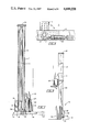
FIG. 1 is a side elevational view of an earlier, prior art cargo loader;
FIG. 2 is an enlarged fragmentary perspective view of one of the open ends of the prior art loader illustrated in FIG. 1;
FIG. 3 is a relatively reduced perspective view of a mobile cargo loader according to the present invention in which the fluid-pressure responsive devices are shown in phantom outline within the sleeves and posts, and in which the frame is partially elevated from the base assemblies;
FIG. 4 is a side elevational view of a cargo loader according to the present invention and particularly illustrates the proximity of the cargo-engaging, pivotal dogs to the ground when the frame is in its lowest position;
FIG. 5 is a top plan view of the cargo loader shown in FIG. 2 and particularly illustrates the preferred manner in which the cargo is positioned theron;
FIG. 6 is an enlarged, fragmentary top plan view of one of the beams of the present loader and particularly illustrates the preferred cargo-engaging dogs pivotally mounted thereon;
FIG. 7 is a vertical sectional view taken along lines 7--7 of FIG. 5 and particularly illustrates the preferred manner in which the post, telescoping sleeve, and cargo-engaging dogs are constructed;
FIG. 8 is a front elevational view, partially broken away, of one of the sleeves in a raised position relative to the post extending therein; and
FIG. 9 is a side elevational view of the present loader with the frame in an elevated position and particularly illustrates the preferred manner in which a building module is maneuvered onto a highway semitrailer.
BEST MODE FOR CARRYING OUT THE INVENTION
As indicated in FIG. 3, a mobile cargo loader according to the present invention basically comprises a generally U-shaped load-bearing frame, generally designated 10, that defines an open, cargo-receiving space 11, a pair of base assemblies generally designated 12, and fluid pressure responsive devices 13 extending from each of the base assemblies to the frame for adjusting the height of the frame relative to the base assemblies. The frame 10 includes a pair of relatively spaced apart elongated beams 14, cargo-engaging devices 15 carried on the beams, a cross member 16 connected to the beams to form a closed end of the frame, a pair of elongated sleeves 17 each carried on one of the beams in angular relation thereto, and a device 18 for attaching the frame to a source of propulsion 19 (FIG. 9). Each of the base assemblies 12 includes an elongated post 20 extending telescopically into one of the sleeves 17, a carriage portion, generally designated 21, connected to and supporting the post, and a ground wheel 22 rotatably mounted on the carriage portion.
The cargo which the present loader or transporter was designed to carry comprises prefabricated building modules 23 (FIGS. 5 and 9) that weigh approximately five tons each and that are usually equipped with plumbing fixtures, kitchen appliances, finished interior walls and the like. These building modules 23 can be damaged extensively if subjected to various bending or twisting forces, so it is important to construct the present cargo loader sturdily to prevent such forces from reaching the module.
Accordingly, the beams 14, cross member 16 and sleeves 17, as well as the posts 20 and portions of the carriages 21, are preferably formed from box-like tubular steel members generally rectangular in cross sectional configuration. These members are sufficient in size and thickness to withstand the torsional and bending forces that arise when the present loader is shuttling the modules across uneven driveways and storage areas. In addition, the cross member 16 may be provided with enlarged corner portions 24, defined by upper and lower L-shaped plates, to provide additional reinforcement and support for the beams 14 and cross member 16.
Additional strength is preferably obtained as follows. The device 18 for attaching the frame 10 to a source of propulsion 19 is a socket-bearing hitch member that extends outwardly from and is rigidly secured to the cross member 16. Alternatively, the source of propulsion 19 may be built into the present loader, rather than being supplied by an auxiliary vehicle such as the forklift 19 illustrated in FIG. 9. In any event, the hitch assembly 18 may include a number of reinforcing flanges, webs and plates disposed in a manner well known in the art to strengthen the hinge and its connection to the cross member 16. In addition, all of the connections between the beams 14, cross member 16, sleeves 17 and hitch assembly 18 may be welded. Likewise, the posts 20 may be welded to the carriage portions 21. The cross member 16, however, may be provided advantageously with a removable central section that is bolted into place. In this manner, the frame may be divided in half to ease shipment.
While the elongated frame beams 14 are, for the most part, of hollow box-like construction, the frame 10 is preferably provided with a set of guard plates 25 projecting generally forwardly and outwardly from the free ends of each of the beams 14. The guard plates 25 create a funnel-like module-receiving opening, thereby protecting the cargo from the wheels 22 and corners of the frame as the loader is advanced into a cargo-carrying position, and as the frame is lifted to engage the building module.
As best indicated in FIGS. 5-7, the cargo-engaging devices 15 preferably consist of the following components. Disposed below the lower wall of each of the beams 14 are a pair of relatively spaced apart, pivotal lifting bars or dogs 15. Each dog 15 is a relatively thick, steel plate-like structure provided on the upper surface thereof with a plurality of weld beads. These protruberances assist in gripping the base of the building module 23 and thereby resist shifting movement of the cargo as it is being transported. Each of the dogs 15 is pivotally or rotatively carried on one of the beams 14 by means of a cylindrical post 26 that extends through said beam and that is rigidly secured to a base portion of the dog. The upper end of the post 26 projects above the upper surface of the beam 14 and is provided with a crank plate 27 that has an eccentric portion to which the piston of a hydraulic motor 28 is attached. By activating the hydraulic motor 28, the operator of the forklift 19 is able to pivot the dogs 15 between retracted positions generally aligned with the beams 14 and extended positions wherein the dogs project generally perpendicularly from said beams into the cargo-receiving space 11.
As indicated in FIGS. 4, 7 and 8, the sleeves 17 are preferably constructed in the following manner. A reinforced steel plate or cap 29 is welded or otherwise rigidly secured to the top of each sleeve and serves as a mount and an endstop for one end of the hydraulic jack 13 depending therefrom. The sleeves 17 project upwardly from the free ends of their respective beams 14 and are welded to the lateral outer surfaces of said beams in generally perpendicular relation thereto. Additional reinforcement for the sleeve to beam connection is provided by a diagonally disposed, reinforcing strut 30 that is welded to each of the sleeves 17 and adjoining frame beams 14. Diagonally projecting bracket plates 31 are welded to adjacent front surfaces of the beams 14 and sleeves 17 and to adjoining portions of the guard plates 25. Alternatively, the struts 30 and bracket plates 31 could be dispensed with, and the sleeves 17 could be rotatively or pivotally mounted on the beams 14, provided that such junctions were strong enough to convey the lifting forces exerted on the sleeves by the jacks 13 to the beams 14, and further provided that the guard plates 25 were adequately supported in some other manner.
As indicated in FIGS. 7-9, each of the ground-engaging base assemblies 12 is preferably constructed as follows. The post 20, like the sleeve 17 within which it is slidably and telescopically mounted, is an elongated, box-like column. Since the post 20 and sleeve 17 have noncircular cross-sectional configurations, said sleeve, being secured to one of the beams 14, prevents said post from rotating about its longitudinal axis. Alternatively, the sleeve 17 and post 20 could be cylindrical and provided with cooperative spline and groove members. In either case, the wheels 22 are prevented from toeing inwardly or outwardly so that the direction of travel of the loader can be controlled. The post 20 is mounted on a carriage assembly 21 which includes a platform 32, a laterally offset, forwardly projecting wheel-supporting arm 33 and a non-rotative axle block 34. Said carriage members are disposed predominantly below the wheel axle 35 so that the cargo-engaging dogs 15 can be positioned as close to the ground as possible. For the same reason, the bottom edge of the sleeve 17 is substantially higher on the lateral outer surface thereof than on the inner, beam-adjoining surface. In this manner, the support arm 33 of the carriage does not interfere with the downward movement of the sleeve 17. In order for the base assembly 12 to be mobile, however, the axle block 34 projects upwardly from the forward end of the support arm 33 and houses the axle 35 of the wheel 22. Preferably, the axle 35 is fixed relative to the axle block 34 and is rotatably mounted in the wheel 22.
It is advantageous to employ relatively elongated sleeves 17 and posts 20 for several reasons. First, in order for the present loader to lift the building module 23 (FIG. 9) sufficiently to clear one end of a semitrailer 36 on which said module is being loaded, the fluid pressure responsive devices 13 extending from the base assemblies 12 to the frame 10 must be quite long. Since these lifting devices 13 are preferably elongated hydraulic jacks disposed within the telescoping sleeves 17 and posts 20, said sleeves and posts must be sufficiently long to accommodate said jacks. Furthermore, a substantial amount of overlap between the telescoping posts 20 and sleeves 17 is needed to keep the wheels 22 properly aligned with the frame beams 14 while the cargo-laden frame 10 is in an elevated position and the present transporter is being moved by the fork lift 19.
As indicated in FIGS. 4 and 5, a plurality of hydraulic fluid and electrical conduits 37 are mounted on the frame 10. As may be readily understood, pairs of hydraulic fluid lines extend from each of the hydraulic jacks 13 mounted in the telescoping posts 20 and sleeves 17, as well as from the dog-driving hydraulic motors 28, to the hitch 18. Suitable couplings, valve mechanisms, pumps, reservoirs and controls, well known in the art, are preferably disposed within the propelling vehicle 19 (FIG. 9), although it would be possible to equip the present loader with such devices, in the event that said loader were self propelled. In addition, at least one of the conduits 37 carries electrical wiring connected to limit switches (not shown) that open and close in response to the positions of the dogs 15, or the drive mechnaisms connected thereto, and to indicator lights 38 that are mounted on opposite sides of the frame cross member 16 in order to be visible to the operator of the forklift 19. In this manner, the operator can know the position of the cargo-engaging dogs 15 without leaving the propelling vehicle before raising or lowering the frame 10.
The present cargo loader is operated in the following manner. As indicated in FIG. 9, a hitch plate 39 is mounted on the load-bearing forks of the lift 19. The operator maneuvers the forklift 19 so that the hitch plate 39 engages the hitch member 18 extending rearwardly from the frame cross member 16. Couplings are then made between the hydraulic and electrical lines 37 of the present loader and those provided on the forklift 19. Next, the operator raises the frame 10 off of the ground via the controls for the hydraulic jacks 13 and the controls for the forks of the lift 19. The loader is then maneuvered to the end of the assembly line and positioned so that the beam guards 25 are disposed adjacent to opposite corners of one end of the building module 23. The lift operator checks the position-indicating lights 38 to see that the dogs 15 are aligned with the beams 14 and lowers the frame 10 until said dogs and cross members 16 are barely off of the assembly line floor. The loader is then advanced until the beams 14 surround the opposing longitudinal sides of the module 23. The dogs 15 are pivoted inwardly, and the indicator lights 38 are checked to see that said dogs are properly positioned. The controls for the jacks 13 and forks of the lift 19 are then engaged to lift the module off of the assembly line.
The operator then backs the cargo-laden loader away from the assembly line and transports the module 23 to either a temporary cradle (not shown) or to a highway semitrailer 35, whereupon the frame 10 must be elevated sufficiently to clear the semitrailer. The loader is advanced so that the wheels 22 and base assemblies 12 are disposed on opposite sides of the semitrailer, and the building module 23 is centered over the load-carrying portion thereof. The controls for the jacks 13 and forks of the lift 19 are then manipulated to tilt the frame 10 so that the module 23 is inclined to conform to the inclined bed of the semitrailer 35. Since the dogs 15 are provided with protuberances, they are able to grip the undersurface of the module 23 and prevent it from sliding or shifting when one portion of the frame 10 is lower than another. The module 23 is then lowered onto the semitrailer 35. The frame 10 is then lowered further, the dogs 15 are pivoted into alignment with the beams 14, and the loader is backed away from the semitrailer.
Thus it can be seen that the present cargo loader is stable, relatively easy to maneuver and highly protective of the building modules it carries. All of the components of the loader that are disposed adjacent to the cargo move with said cargo when it is being elevated or lowered. This is particularly true of the sleeves which not only protect the modules and the hydraulic jacks contained therein, but also serve as the means by which the wheels and base assemblies are maintained in proper alignment with the frame as the loader is maneuvered between the assembly line and the shipping yard.
While a single preferred embodiment of the present invention has been illustrated and described in some detail, several modifications could be made without departing from the spirit of the invention or the scope of the following claims.

Claims (2)

We claim:
1. A mobile cargo loader comprising:
(a) a generally U-shaped load-bearing frame defining an open cargo-receiving space and including a pair of relatively spaced apart, generally horizontally disposed, elongated beams;
(b) cargo-engaging means carried on each of the beams and movable into and out of said cargo-receiving space;
(c) an upwardly projecting elongated guide sleeve of generally rectangular cross-sectional configuration rigidly connected with each of the beams in laterally outwardly spaced relation to the cargo-receiving space;
(d) means for attaching the frame to a source of propulsion;
(e) an upwardly projecting, elongated, hollow post of rectangular cross-section telescopically and nonrotatably carried in each of the sleeves;
(f) carriage means connected to a lower end of each post and disposed outboard of said cargo-receiving space;
(g) a ground wheel rotatively mounted on the carriage means adjacent each post; and
(h) an elongated, fluid pressure responsive lifting device mounted within each of the relatively telescoping posts and sleeves for raising and lowering the sleeves and frame relative to the posts, carriage means and wheels.
2. A mobile cargo loader according to claim 1, wherein each of the elongated beams of the load-bearing frame is a box-like structure having upper, lower and side surfaces, wherein the cargo-engaging means comprise at least one dog pivotally mounted on the lower surface of each of the beams, and wherein at least one fluid pressure responsive actuator is disposed on the upper surface of each of the beams for rotating the dog between a relatively inturned position aligned with said beams and an extended position projecting into the cargo-receiving space.
US06/822,533 1986-01-27 1986-01-27 Mobile cargo loader for lifting and transporting building modules and the like Expired - Fee Related US4699558A (en)

Priority Applications (1)

Application Number Priority Date Filing Date Title
US06/822,533 US4699558A (en) 1986-01-27 1986-01-27 Mobile cargo loader for lifting and transporting building modules and the like

Applications Claiming Priority (1)

Application Number Priority Date Filing Date Title
US06/822,533 US4699558A (en) 1986-01-27 1986-01-27 Mobile cargo loader for lifting and transporting building modules and the like

Publications (1)

Publication Number Publication Date
US4699558A true US4699558A (en) 1987-10-13

Family

ID=25236299

Family Applications (1)

Application Number Title Priority Date Filing Date
US06/822,533 Expired - Fee Related US4699558A (en) 1986-01-27 1986-01-27 Mobile cargo loader for lifting and transporting building modules and the like

Country Status (1)

Country Link
US (1) US4699558A (en)

Cited By (25)

* Cited by examiner, † Cited by third party
Publication number Priority date Publication date Assignee Title
US4880347A (en) * 1988-03-22 1989-11-14 Luis A. Gigueroa Load-carrying attachment for motor vehicles
US4943193A (en) * 1987-07-08 1990-07-24 Rautaruukki Oy Loading trailer
US5052877A (en) * 1989-07-04 1991-10-01 Nokia-Maillefer Holding S.A. Carriage for the transportation of a cylindrical object
US5417539A (en) * 1993-07-26 1995-05-23 Jurjen Van Der Wal, Revocable Family Trust Transportation trailer for a modular home unit
US5584639A (en) * 1994-10-14 1996-12-17 Walker, Jr.; Esler C. Tow trailer for transporting pallets
US6196785B1 (en) 1998-08-21 2001-03-06 Laurel Anne Lanciaux Attachable frame and wheels for lifting and moving a container
US6431805B2 (en) 1999-08-20 2002-08-13 Francis E. Lanciaux, Jr. Attachable frame for lifting and moving a container
US20030140526A1 (en) * 2002-01-10 2003-07-31 Thomas Dennis R. Universal trailer for a longwall roof support for longwall underground mining
US6612601B1 (en) * 1998-04-21 2003-09-02 Hans Ingmar Granlind Boat wagon
US20040258509A1 (en) * 2003-06-06 2004-12-23 Kenneth Doeden Slat carrier
US20050056753A1 (en) * 2003-09-17 2005-03-17 Karamanos John Chris Method for transporting a piping structure
EP1642488A1 (en) * 2004-10-01 2006-04-05 Viking GmbH Mobile working apparatus
US20060115352A1 (en) * 2004-11-30 2006-06-01 Brown J C Tow trailer assembly
WO2007106735A2 (en) * 2006-03-10 2007-09-20 Mcgurn Arthur S Apparatus for lifting and transporting a container
FR2926799A1 (en) * 2008-01-29 2009-07-31 Eric Bonamy Two stage semi-trailer truck for e.g. loading carpet roll into lorry, has chassis provided with wheels and hook for handling truck by transpallet or stacker, when hook enters into slot at front of one of forks in transpallet or stacker
US20090272631A1 (en) * 2007-02-08 2009-11-05 Prairie Machine & Parts Mfg.(1978) Ltd. Steerable conveyor with height adjustable wheels
US20100104408A1 (en) * 2008-10-28 2010-04-29 Gaudet Joel Trailer for transporting freight containers and method of use
US20100178143A1 (en) * 2009-01-06 2010-07-15 Judson Smith Axleless flex floor trailer and truck
US20120213622A1 (en) * 2011-02-18 2012-08-23 Doskocil David L Level lift detachable trailer system
US8870517B2 (en) 2011-12-08 2014-10-28 Sean Jones Container loading and unloading system
US20150298593A1 (en) * 2014-04-21 2015-10-22 Dennis R. POLZIN Boat lift moving apparatus and method
US20170253166A1 (en) * 2016-03-03 2017-09-07 2222035 Ontario Inc. System and Method for Loading a Container For Transport
US10471980B1 (en) * 2017-10-04 2019-11-12 Itool Equipment Holding Llc Stackable knock-down material cart with adaptable forklift mounts
US11034372B1 (en) * 2017-10-04 2021-06-15 Itool Equipment Holding Llc Elevated forklift mount for a material cart
US20210276646A1 (en) * 2020-03-06 2021-09-09 Terry Repp Trailer and interchangeable modules

Citations (11)

* Cited by examiner, † Cited by third party
Publication number Priority date Publication date Assignee Title
US2512333A (en) * 1948-09-18 1950-06-20 Jaffa Harry Material handling apparatus
US3018905A (en) * 1959-03-23 1962-01-30 Walter E Thornton-Trump Mobile power-operated bin handling and transporting vehicle
FR1545843A (en) * 1967-09-25 1968-11-15 Co Reel Improvements to handling vehicles of the kind of trinqueballes and the like
US3529736A (en) * 1968-01-02 1970-09-22 Lebre Charles J P Devices for raising loads to permit the handling thereof
DE2030524A1 (en) * 1970-06-20 1971-12-30 Westerwälder Blumentopffabrik Spang & Co, 5412 Baumbach Transport trolley for moving flower pots or other objects packed on pallets, e.g. tubes or the like
DE2046238A1 (en) * 1970-09-18 1972-03-23 The Budd Co., Philadelphia, Pa. (V.StA.) Passenger transfer vehicle
US3861535A (en) * 1973-06-29 1975-01-21 Automation Ag Straddle fork vehicle
US3972308A (en) * 1974-10-03 1976-08-03 Ray Daniel F Apparatus for moving and self-feeding of large haystacks
SU645890A2 (en) * 1976-02-24 1979-02-05 Сибирский научно-исследовательский и проектный институт газонефтепромыслового строительства Trailer for carrying large loads
US4232879A (en) * 1979-02-09 1980-11-11 Boxrud Phillip E Equipment trailer
US4392662A (en) * 1980-07-10 1983-07-12 Hoeglinger Norbert Device for facilitating particularly the loading and unloading of containers etc. from vehicles etc.

Patent Citations (11)

* Cited by examiner, † Cited by third party
Publication number Priority date Publication date Assignee Title
US2512333A (en) * 1948-09-18 1950-06-20 Jaffa Harry Material handling apparatus
US3018905A (en) * 1959-03-23 1962-01-30 Walter E Thornton-Trump Mobile power-operated bin handling and transporting vehicle
FR1545843A (en) * 1967-09-25 1968-11-15 Co Reel Improvements to handling vehicles of the kind of trinqueballes and the like
US3529736A (en) * 1968-01-02 1970-09-22 Lebre Charles J P Devices for raising loads to permit the handling thereof
DE2030524A1 (en) * 1970-06-20 1971-12-30 Westerwälder Blumentopffabrik Spang & Co, 5412 Baumbach Transport trolley for moving flower pots or other objects packed on pallets, e.g. tubes or the like
DE2046238A1 (en) * 1970-09-18 1972-03-23 The Budd Co., Philadelphia, Pa. (V.StA.) Passenger transfer vehicle
US3861535A (en) * 1973-06-29 1975-01-21 Automation Ag Straddle fork vehicle
US3972308A (en) * 1974-10-03 1976-08-03 Ray Daniel F Apparatus for moving and self-feeding of large haystacks
SU645890A2 (en) * 1976-02-24 1979-02-05 Сибирский научно-исследовательский и проектный институт газонефтепромыслового строительства Trailer for carrying large loads
US4232879A (en) * 1979-02-09 1980-11-11 Boxrud Phillip E Equipment trailer
US4392662A (en) * 1980-07-10 1983-07-12 Hoeglinger Norbert Device for facilitating particularly the loading and unloading of containers etc. from vehicles etc.

Cited By (32)

* Cited by examiner, † Cited by third party
Publication number Priority date Publication date Assignee Title
US4943193A (en) * 1987-07-08 1990-07-24 Rautaruukki Oy Loading trailer
US4880347A (en) * 1988-03-22 1989-11-14 Luis A. Gigueroa Load-carrying attachment for motor vehicles
US5052877A (en) * 1989-07-04 1991-10-01 Nokia-Maillefer Holding S.A. Carriage for the transportation of a cylindrical object
US5417539A (en) * 1993-07-26 1995-05-23 Jurjen Van Der Wal, Revocable Family Trust Transportation trailer for a modular home unit
US5584639A (en) * 1994-10-14 1996-12-17 Walker, Jr.; Esler C. Tow trailer for transporting pallets
US6612601B1 (en) * 1998-04-21 2003-09-02 Hans Ingmar Granlind Boat wagon
US6196785B1 (en) 1998-08-21 2001-03-06 Laurel Anne Lanciaux Attachable frame and wheels for lifting and moving a container
US6431805B2 (en) 1999-08-20 2002-08-13 Francis E. Lanciaux, Jr. Attachable frame for lifting and moving a container
US20030140526A1 (en) * 2002-01-10 2003-07-31 Thomas Dennis R. Universal trailer for a longwall roof support for longwall underground mining
US20040258509A1 (en) * 2003-06-06 2004-12-23 Kenneth Doeden Slat carrier
US7246986B2 (en) 2003-06-06 2007-07-24 Kenneth Doeden Slat carrier
US20050056753A1 (en) * 2003-09-17 2005-03-17 Karamanos John Chris Method for transporting a piping structure
EP1642488A1 (en) * 2004-10-01 2006-04-05 Viking GmbH Mobile working apparatus
US7326022B2 (en) * 2004-11-30 2008-02-05 Brown James C Tow trailer assembly
US20060115352A1 (en) * 2004-11-30 2006-06-01 Brown J C Tow trailer assembly
WO2007106735A2 (en) * 2006-03-10 2007-09-20 Mcgurn Arthur S Apparatus for lifting and transporting a container
US20070231113A1 (en) * 2006-03-10 2007-10-04 Mcgurn Arthur S Apparatus and method for lifting and transporting a container with an independent mechanized unit
WO2007106735A3 (en) * 2006-03-10 2008-12-04 Arthur S Mcgurn Apparatus for lifting and transporting a container
US20090272631A1 (en) * 2007-02-08 2009-11-05 Prairie Machine & Parts Mfg.(1978) Ltd. Steerable conveyor with height adjustable wheels
FR2926799A1 (en) * 2008-01-29 2009-07-31 Eric Bonamy Two stage semi-trailer truck for e.g. loading carpet roll into lorry, has chassis provided with wheels and hook for handling truck by transpallet or stacker, when hook enters into slot at front of one of forks in transpallet or stacker
US8182193B2 (en) * 2008-10-28 2012-05-22 Max-Atlas Trailer for transporting freight containers and method of use
US20100104408A1 (en) * 2008-10-28 2010-04-29 Gaudet Joel Trailer for transporting freight containers and method of use
US20100178143A1 (en) * 2009-01-06 2010-07-15 Judson Smith Axleless flex floor trailer and truck
US20120213622A1 (en) * 2011-02-18 2012-08-23 Doskocil David L Level lift detachable trailer system
US8870517B2 (en) 2011-12-08 2014-10-28 Sean Jones Container loading and unloading system
US9969314B2 (en) 2011-12-08 2018-05-15 Sean Jones Container loading and unloading system
US20150298593A1 (en) * 2014-04-21 2015-10-22 Dennis R. POLZIN Boat lift moving apparatus and method
US20170253166A1 (en) * 2016-03-03 2017-09-07 2222035 Ontario Inc. System and Method for Loading a Container For Transport
US10479256B2 (en) * 2016-03-03 2019-11-19 2222035 Ontario Inc. System and method for loading a container for transport
US10471980B1 (en) * 2017-10-04 2019-11-12 Itool Equipment Holding Llc Stackable knock-down material cart with adaptable forklift mounts
US11034372B1 (en) * 2017-10-04 2021-06-15 Itool Equipment Holding Llc Elevated forklift mount for a material cart
US20210276646A1 (en) * 2020-03-06 2021-09-09 Terry Repp Trailer and interchangeable modules

Similar Documents

Publication Publication Date Title
US4699558A (en) Mobile cargo loader for lifting and transporting building modules and the like
US4065012A (en) Low lift truck
EP1259398B1 (en) An apparatus for lifting, handling and transporting a container
US5288197A (en) Equipment trailer
US6939098B2 (en) Straddle carrier
US5582501A (en) Fork lift and method for operating and transporting same
US7428940B2 (en) Steerable transport trolley
US3521780A (en) Truck-mounted lifting device
JP2003505313A (en) Container handling equipment or underframe
US3468440A (en) Vehicles
CA1135222A (en) Cantilever straddle carrier
US3884494A (en) Apparatus for transporting house structures or the like
GB2113175A (en) A vehicle
US4387813A (en) Movable ring supported lift crane
EP0906241B1 (en) A straddle carrier
FI79985C (en) Lifting Trolley
US3768670A (en) Carrier for a heavy load including a boom
US3258135A (en) Apparatus for transporting and handling large tubular structural sections
US4273500A (en) Low profile lift attachment for a forklift
US3841509A (en) Apparatus for transporting one vehicle by another
US4326830A (en) Side loading vehicle
US3033400A (en) Power lift for trailer
EP1388519A2 (en) Fork-lift truck and load handling method
EP0553067B1 (en) A fork-lift truck
US4338059A (en) Cable reel handling apparatus for a vehicle

Legal Events

Date Code Title Description
AS Assignment

Owner name: CARDINAL INDUSTRIES, INC., 2040 SOUTH HAMILTON ROA

Free format text: ASSIGNMENT OF ASSIGNORS INTEREST.;ASSIGNORS:HAGGE, DOUGLAS R.;JOHNSTON, CLIFFORD V.;REEL/FRAME:004509/0906

Effective date: 19851231

FPAY Fee payment

Year of fee payment: 4

AS Assignment

Owner name: HUNGTINGTON NATIONAL BANK, THE, OHIO

Free format text: ASSIGNMENT OF ASSIGNORS INTEREST.;ASSIGNOR:CARDINAL INDUSTRIES, INC.;REEL/FRAME:006451/0835

Effective date: 19920911

REMI Maintenance fee reminder mailed
LAPS Lapse for failure to pay maintenance fees
FP Lapsed due to failure to pay maintenance fee

Effective date: 19951018

STCH Information on status: patent discontinuation

Free format text: PATENT EXPIRED DUE TO NONPAYMENT OF MAINTENANCE FEES UNDER 37 CFR 1.362