US468686A - Electric governor - Google Patents
Electric governor Download PDFInfo
- Publication number
- US468686A US468686A US468686DA US468686A US 468686 A US468686 A US 468686A US 468686D A US468686D A US 468686DA US 468686 A US468686 A US 468686A
- Authority
- US
- United States
- Prior art keywords
- resistance
- contact
- armature
- circuit
- governor
- Prior art date
- Legal status (The legal status is an assumption and is not a legal conclusion. Google has not performed a legal analysis and makes no representation as to the accuracy of the status listed.)
- Expired - Lifetime
Links
- OKTJSMMVPCPJKN-UHFFFAOYSA-N carbon Chemical compound [C] OKTJSMMVPCPJKN-UHFFFAOYSA-N 0.000 description 10
- 229910052799 carbon Inorganic materials 0.000 description 10
- 230000000875 corresponding Effects 0.000 description 6
- 210000003414 Extremities Anatomy 0.000 description 2
- 238000010276 construction Methods 0.000 description 2
- 230000001276 controlling effect Effects 0.000 description 2
- 239000011810 insulating material Substances 0.000 description 2
Images


Classifications
-
- H—ELECTRICITY
- H02—GENERATION; CONVERSION OR DISTRIBUTION OF ELECTRIC POWER
- H02J—CIRCUIT ARRANGEMENTS OR SYSTEMS FOR SUPPLYING OR DISTRIBUTING ELECTRIC POWER; SYSTEMS FOR STORING ELECTRIC ENERGY
- H02J3/00—Circuit arrangements for ac mains or ac distribution networks
- H02J3/12—Circuit arrangements for ac mains or ac distribution networks for adjusting voltage in ac networks by changing a characteristic of the network load
- H02J3/14—Circuit arrangements for ac mains or ac distribution networks for adjusting voltage in ac networks by changing a characteristic of the network load by switching loads on to, or off from, network, e.g. progressively balanced loading
-
- H—ELECTRICITY
- H02—GENERATION; CONVERSION OR DISTRIBUTION OF ELECTRIC POWER
- H02J—CIRCUIT ARRANGEMENTS OR SYSTEMS FOR SUPPLYING OR DISTRIBUTING ELECTRIC POWER; SYSTEMS FOR STORING ELECTRIC ENERGY
- H02J2310/00—The network for supplying or distributing electric power characterised by its spatial reach or by the load
- H02J2310/50—The network for supplying or distributing electric power characterised by its spatial reach or by the load for selectively controlling the operation of the loads
- H02J2310/56—The network for supplying or distributing electric power characterised by its spatial reach or by the load for selectively controlling the operation of the loads characterised by the condition upon which the selective controlling is based
- H02J2310/58—The condition being electrical
-
- Y—GENERAL TAGGING OF NEW TECHNOLOGICAL DEVELOPMENTS; GENERAL TAGGING OF CROSS-SECTIONAL TECHNOLOGIES SPANNING OVER SEVERAL SECTIONS OF THE IPC; TECHNICAL SUBJECTS COVERED BY FORMER USPC CROSS-REFERENCE ART COLLECTIONS [XRACs] AND DIGESTS
- Y02—TECHNOLOGIES OR APPLICATIONS FOR MITIGATION OR ADAPTATION AGAINST CLIMATE CHANGE
- Y02B—CLIMATE CHANGE MITIGATION TECHNOLOGIES RELATED TO BUILDINGS, e.g. HOUSING, HOUSE APPLIANCES OR RELATED END-USER APPLICATIONS
- Y02B70/00—Technologies for an efficient end-user side electric power management and consumption
- Y02B70/30—Systems integrating technologies related to power network operation and communication or information technologies for improving the carbon footprint of the management of residential or tertiary loads, i.e. smart grids as climate change mitigation technology in the buildings sector, including also the last stages of power distribution and the control, monitoring or operating management systems at local level
- Y02B70/3225—Demand response systems, e.g. load shedding, peak shaving
-
- Y—GENERAL TAGGING OF NEW TECHNOLOGICAL DEVELOPMENTS; GENERAL TAGGING OF CROSS-SECTIONAL TECHNOLOGIES SPANNING OVER SEVERAL SECTIONS OF THE IPC; TECHNICAL SUBJECTS COVERED BY FORMER USPC CROSS-REFERENCE ART COLLECTIONS [XRACs] AND DIGESTS
- Y04—INFORMATION OR COMMUNICATION TECHNOLOGIES HAVING AN IMPACT ON OTHER TECHNOLOGY AREAS
- Y04S—SYSTEMS INTEGRATING TECHNOLOGIES RELATED TO POWER NETWORK OPERATION, COMMUNICATION OR INFORMATION TECHNOLOGIES FOR IMPROVING THE ELECTRICAL POWER GENERATION, TRANSMISSION, DISTRIBUTION, MANAGEMENT OR USAGE, i.e. SMART GRIDS
- Y04S20/00—Management or operation of end-user stationary applications or the last stages of power distribution; Controlling, monitoring or operating thereof
- Y04S20/20—End-user application control systems
- Y04S20/222—Demand response systems, e.g. load shedding, peak shaving
Definitions
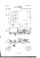
- FIG. 1 is a front elevation of my im proved electrical governor.
- Fig. 2 is a sectional end elevation.
- Fig. 3 is a rear elevation of one end, showing the electrical connections.
- Fig. 4 is an enlarged sectional end elevation showing the construction of the parts in detail; and
- Fig. 5 is a diagrammatical View of the governor, showing the circuits.
- the object'of my invention is to construct an electrical governor for controlling the current on a circuit by introducing resistance into the circuit or removing it therefrom, or by changing the exciting-current in the fieldmagnet of an electrical generator.
- My invention consists in the combination of a curved solenoid. a curved perpendicular armature, a series of contacts, a circuit closer and opener operated by the perpendiculararmature, a series of resistance-coils, and a series of electro-mngnetic cut-outs; also, in the combination, with the perpendicular armature, of an air dash-pot for modifying its movements, all as will be hereinafter more fully described.
- a curved solenoid B adapted to receive the entire current to be controlled by the governor.
- a curved solenoid B To the curved solenoid B is fitted a curved armature (3, which is suspended by rods a from a shaft 1), turning on centers 1).
- an insulating-bar E To the back of the casing A is secured an insulating-bar E, to the front side of which are attached the angled contact-pieces c c c c c c o c c 0 0 &c., and to the back side of the insulating-bar E is secured a corresponding number of contact-pieces d d, &c.
- an arm 6 which is pivoted to therod f, having at its free extremity a fork g, in which is journaled a metallic grooved contact-roller I which rolls.
- the said contact-pieces are separated by a bar h'of insulating material secured to the bar E and forming a guide for the contactroller F.
- the rod f, which carries the contact-roller F, is divided and furnished with an insulating-section v
- To the end of the armature O is pivotally connected the pistonrod 7' of the dash-pot In, which modifies the movements of the armature.
- the oontact-piece c is connected with the bindingpost m, which is common to the coils U.
- the binding-post c is connected electrically with the binding-post m which is common to the coils Z Z and this order of connection is carried out through the entire series of contactpieces and resistance-coils.
- a latch 0 To a post u, projecting from the back of the casing A,'is pivoted a latch 0, which is furnished with a square shoulder w, engaged by the spring at, secured to the post.
- the armature-leverp is provided with a spring g, which surrounds its pivot and tends to draw the armature away from the magnet 12 and close the circuit between the carbon contact-piece q and carbon bar 0'.
- the resistance-coils ZZ, &c. have a uniform resistance adapted to the current flowing in the circuit in which the governor is used, and the magnets 07. n, &c., have the same resistance.
- a switch z is provided, by means of which the solenoid B may be shortcircuited.
- the solenoid B is in the main circuit and the strip 0' and binding-posts s are in branches of the main circuit H, which include storagebatteries 1, or, in lieu thereof, motors or re sistance.
- the current entering the apparatus by the binding-post 0' is conveyed to the bindingpost m whence it passes through the resistance-coilsl"Z 1 1 Z Z Z to the contact-piece 0 the roller F, contact-piece d and wire connected therewith, through the magnets min, and n, thence to the binding-post 0.
- the magnets n n 02 being energized, attract their armatures and break the branch circuits which they control. Any movement of the roller F toward the solenoi B cuts out the resistance-coils Z Z 1*, &c., in succession and cuts in in lieu of the said coils the magnets n n M, &c., in succession, thus keeping the resistance offered by the apparatus to the passing current always constant.
- circuit-controller formed of the insulating-bar E, contact-pieces c c d d, &c., attached to the said bar, translating devices and resistances connected with the said contact-pieces, the guiding-bar h, the grooved roller-F, and the solenoid B and armature C for moving the same, substantially as specified.
Landscapes
- Engineering & Computer Science (AREA)
- Power Engineering (AREA)
- Electromagnets (AREA)
Description
(No Model.) 3 Sheets-Sheet 1. J T OBRIAN ELEGTRIG GOVERNOR.
No. 468,686. Patented Feb. 9, 1892.
IN VENTOR WITNESSES: MW
A TTORNE Y8 3 Sheets-Sheet 2.
(No Model.)
J T OBRIAN ELECTRIC GOVERNOR;
Patented Feb. 9, 1892.
INVENTOR: (Z0
4% w ATTORNEYS WITNESSES (No Model.) 3 Sheets-8heet 3,
' J T OBRIAN ELEGTRIG GOVERNOR.
No. 468,686. Patented Feb. 9, 1892.
INVENTOI? 6. was 8 Q ATTORNEYS.
arts grnirns PATENT OFFICE.-
JOHN T. OBRIAN, OF KEARNEY, NEBRASKA.
ELECTRIC GOVERNOR.
SPECIFICATION forming part of Letters Patent No. 468,686, dated February 9, 1892. Application filed February 9, 1891- SerialNo. 380.753- (No model.)
To aZZ whom it nuty concern.-
Be it known that I, JOHN T. OBRIAN, of Kearney, in the county of Buffalo and State of Nebraska, have invented a new and Improved Electrical Governor, of which the following is a specification, reference being had to the annexed drawings, forming a part thereof, in
which- Figure l is a front elevation of my im proved electrical governor. Fig. 2 is a sectional end elevation. Fig. 3 is a rear elevation of one end, showing the electrical connections. Fig. 4 is an enlarged sectional end elevation showing the construction of the parts in detail; and Fig. 5 is a diagrammatical View of the governor, showing the circuits.
Similar letters of reference indicate corresponding parts in all the views.
The object'of my invention is to construct an electrical governor for controlling the current on a circuit by introducing resistance into the circuit or removing it therefrom, or by changing the exciting-current in the fieldmagnet of an electrical generator.
My invention consists in the combination of a curved solenoid. a curved perpendicular armature, a series of contacts, a circuit closer and opener operated by the perpendiculararmature, a series of resistance-coils, and a series of electro-mngnetic cut-outs; also, in the combination, with the perpendicular armature, of an air dash-pot for modifying its movements, all as will be hereinafter more fully described.
To the back of the casing A is secured a curved solenoid B, adapted to receive the entire current to be controlled by the governor. To the curved solenoid B is fitted a curved armature (3, which is suspended by rods a from a shaft 1), turning on centers 1). To the back of the casing A is secured an insulating-bar E, to the front side of which are attached the angled contact-pieces c c c c c c o c c 0 0 &c., and to the back side of the insulating-bar E is secured a corresponding number of contact-pieces d d, &c.
To the shaft D is attached an arm 6, which is pivoted to therod f, having at its free extremity a fork g, in which is journaled a metallic grooved contact-roller I which rolls.
upon the two sets of contacts 0 c d d, &c. The said contact-pieces are separated by a bar h'of insulating material secured to the bar E and forming a guide for the contactroller F. The rod f, which carries the contact-roller F, is divided and furnished with an insulating-section v To the end of the armature O is pivotally connected the pistonrod 7' of the dash-pot In, which modifies the movements of the armature.
In the bottom of the casing Ais supported a series of resistance-coils Z Z Z Z Z Z Z Z Z 1 &c., connected with the binding-posts m m m m m m m m m m m &c., and upon the back of the upper portion of the casingA are secured the magnets n n n n n n n n n n", &c. To the end of the casing A are secured binding-posts 0 0', the binding-post 0 being connected with one terminal of the magnet n and also with the contact-piece d on the vbar E. The corresponding contactpiece 0 is connected electrically with the binding-post m of the resistance-coil Z. The binding-post 0 is connected electrically with the binding-post m of the coil'l Themagnet n is connected with the contact-piece d, and the connections are carried out in a similar way throughout the series of magnets n n,"
&c., and contact-pieces d d, &c. The oontact-piece c is connected with the bindingpost m, which is common to the coils U. The binding-post c is connected electrically with the binding-post m which is common to the coils Z Z and this order of connection is carried out through the entire series of contactpieces and resistance-coils.
Above the magnets n n, &c., are pivoted a series of armature-levers p p 13 19 19 10 12 19 10 19 & c. The armatures upon the lower ends of the levers p p, &c., are opposite the poles of the magnets 02 n, (to, and the upper ends of the said armatures carry carbon contact-pieces q. To the back of the casing A and within the path of the carbon contactpieces q is arranged a carbon bar 4. To the support of each armature-lever p is attached a binding-post 3. To a post u, projecting from the back of the casing A,'is pivoted a latch 0, which is furnished with a square shoulder w, engaged by the spring at, secured to the post. The armature-leverp is provided with a spring g, which surrounds its pivot and tends to draw the armature away from the magnet 12 and close the circuit between the carbon contact-piece q and carbon bar 0'.
The resistance-coils ZZ, &c., have a uniform resistance adapted to the current flowing in the circuit in which the governor is used, and the magnets 07. n, &c., have the same resistance. A switch z is provided, by means of which the solenoid B may be shortcircuited. The solenoid B is in the main circuit and the strip 0' and binding-posts s are in branches of the main circuit H, which include storagebatteries 1, or, in lieu thereof, motors or re sistance.
The current entering the apparatus by the binding-post 0' is conveyed to the bindingpost m whence it passes through the resistance-coilsl"Z 1 1 Z Z Z to the contact-piece 0 the roller F, contact-piece d and wire connected therewith, through the magnets min, and n, thence to the binding-post 0. The magnets n n 02 being energized, attract their armatures and break the branch circuits which they control. Any movement of the roller F toward the solenoi B cuts out the resistance-coils Z Z 1*, &c., in succession and cuts in in lieu of the said coils the magnets n n M, &c., in succession, thus keeping the resistance offered by the apparatus to the passing current always constant.
\Vhenever the current in the main circuit is above the normal, the core 0 is drawn into the solenoid B, moving forward the contactroller F on the contact-pieces c d, &c., thus cutting out one or more of the resistancecoils Z, cutting in one or more of the magnets 71., thereby causing one or more of the armature-levers p p, &c., to be tilted, breaking the circuit between the contact (1 and the bar 0' and allowing the surplus current to go through the storage-batteries I in the storage-battery circuits controlled by the roller F. \Vhen the current in the main circuit diminishes, the roller F returns toward its former position, and in so doing cuts out one or more of the magnets 11, thus allowing the contact (1 to strike the bar 0, which operation cuts out the storage-battery or motor or other translating devices included in the circuit or circuits controlled by the roller F, and also cuts in resistance Z to compensate for the removal of the magnet '21 from the circuit, thus keeping the resistance of the governor constant.
Having thus described my invention, I claim as new and desire to secure by Letters Patent 1.. In an electric governor, the combination of the solenoid B,provided with an armature C, a circuitcontroller carried by the armature, a series of contacts arranged to be connected by the circuit-controller, resistances, and translating devices arranged to be thrown into and out of the circuit by the circuitcontroller, the said resistances and translating devices being made with like resistance to permit of alternating the translating devices and resistances without changing the total resistance of the circuit, substantially as specified.
2. In an electric governor, the combination, with an electromagnetic circuit-controller, of a series of resistance-coils in which the several coils have the same resistance, a series of magnets having like resistance as the resistancecoils, and having the same resistance, and a series of armature-levers operated by the magnets for closing auxiliary circuits, substantially as specified.
3. The circuit-controller formed of the insulating-bar E, contact-pieces c c d d, &c., attached to the said bar, translating devices and resistances connected with the said contact-pieces, the guiding-bar h, the grooved roller-F, and the solenoid B and armature C for moving the same, substantially as specified.
JOHN T. OBRIAN. \Vitnesses:
SAMUEL II. STERNS, GEO. W. BROWN.
Publications (1)
| Publication Number | Publication Date |
|---|---|
| US468686A true US468686A (en) | 1892-02-09 |
Family
ID=2537547
Family Applications (1)
| Application Number | Title | Priority Date | Filing Date |
|---|---|---|---|
| US468686D Expired - Lifetime US468686A (en) | Electric governor |
Country Status (1)
| Country | Link |
|---|---|
| US (1) | US468686A (en) |
Cited By (2)
| Publication number | Priority date | Publication date | Assignee | Title |
|---|---|---|---|---|
| US2843759A (en) * | 1955-10-03 | 1958-07-15 | Pioneer Electric Brandon Ltd | Automatic electric switching system |
| US20040179552A1 (en) * | 1998-04-01 | 2004-09-16 | Panasonic Communications Co., Ltd. | Activation of multiple xDSL modems with implicit channel probe |
-
0
- US US468686D patent/US468686A/en not_active Expired - Lifetime
Cited By (2)
| Publication number | Priority date | Publication date | Assignee | Title |
|---|---|---|---|---|
| US2843759A (en) * | 1955-10-03 | 1958-07-15 | Pioneer Electric Brandon Ltd | Automatic electric switching system |
| US20040179552A1 (en) * | 1998-04-01 | 2004-09-16 | Panasonic Communications Co., Ltd. | Activation of multiple xDSL modems with implicit channel probe |
Similar Documents
| Publication | Publication Date | Title |
|---|---|---|
| US468686A (en) | Electric governor | |
| US502788A (en) | Regulator for electric generators | |
| US405194A (en) | williams | |
| US492036A (en) | Robert t | |
| US279036A (en) | Electric motor | |
| US614472A (en) | John d | |
| US461791A (en) | Sigmund bergmann | |
| US407293A (en) | Daniel iiigham | |
| US726234A (en) | Automatic potential-regulator. | |
| US725800A (en) | Automatic potential-regulator. | |
| US464948A (en) | wheeler | |
| US677360A (en) | Electric-current controller. | |
| US446284A (en) | Automatic potential-regulator for electric currents | |
| US359739A (en) | powers | |
| US693023A (en) | Electromagnetic regulator for electric currents. | |
| US897497A (en) | Starting and speed-regulating rheostat. | |
| US867475A (en) | Motor-starting rheostat. | |
| US1157313A (en) | Electric-motor control. | |
| US555503A (en) | Controlling mechanism for electric motors | |
| US351961A (en) | Automatic electric-current regulator | |
| US555291A (en) | System of control for electric motors | |
| US474953A (en) | Automatic potential-regulator for electric ou rrents | |
| US551635A (en) | Mechanism for admission of currents to motors and regulation of currents in same | |
| US236460A (en) | Automatic regulator for electric currents | |
| US1141548A (en) | Controlling device for motors. |