US4654525A - Optical rotary encoder - Google Patents

Optical rotary encoder Download PDF

Info

Publication number
US4654525A
US4654525A US06/521,933 US52193383A US4654525A US 4654525 A US4654525 A US 4654525A US 52193383 A US52193383 A US 52193383A US 4654525 A US4654525 A US 4654525A
Authority
US
United States
Prior art keywords
output signals
photodiodes
variations
slit plate
developing
Prior art date
Legal status (The legal status is an assumption and is not a legal conclusion. Google has not performed a legal analysis and makes no representation as to the accuracy of the status listed.)
Expired - Lifetime
Application number
US06/521,933
Inventor
Kiyoshi Ebina
Kazuhira Nakao
Zempei Tani
Current Assignee (The listed assignees may be inaccurate. Google has not performed a legal analysis and makes no representation or warranty as to the accuracy of the list.)
Sharp Corp
Original Assignee
Sharp Corp
Priority date (The priority date is an assumption and is not a legal conclusion. Google has not performed a legal analysis and makes no representation as to the accuracy of the date listed.)
Filing date
Publication date
Family has litigation
First worldwide family litigation filed litigation Critical https://patents.darts-ip.com/?family=26467119&utm_source=google_patent&utm_medium=platform_link&utm_campaign=public_patent_search&patent=US4654525(A) "Global patent litigation dataset” by Darts-ip is licensed under a Creative Commons Attribution 4.0 International License.
Priority claimed from JP13257682U external-priority patent/JPS5935821U/en
Priority claimed from JP57152014A external-priority patent/JPS5940258A/en
Application filed by Sharp Corp filed Critical Sharp Corp
Assigned to SHARP KABUSHIKI KAISHA reassignment SHARP KABUSHIKI KAISHA ASSIGNMENT OF ASSIGNORS INTEREST. Assignors: EBINA, KIYOSHI, NAKAO, KAZUHIRA, TANI, ZEMPEI
Application granted granted Critical
Publication of US4654525A publication Critical patent/US4654525A/en
Anticipated expiration legal-status Critical
Expired - Lifetime legal-status Critical Current

Links

Images

Classifications

    • GPHYSICS
    • G01MEASURING; TESTING
    • G01DMEASURING NOT SPECIALLY ADAPTED FOR A SPECIFIC VARIABLE; ARRANGEMENTS FOR MEASURING TWO OR MORE VARIABLES NOT COVERED IN A SINGLE OTHER SUBCLASS; TARIFF METERING APPARATUS; MEASURING OR TESTING NOT OTHERWISE PROVIDED FOR
    • G01D5/00Mechanical means for transferring the output of a sensing member; Means for converting the output of a sensing member to another variable where the form or nature of the sensing member does not constrain the means for converting; Transducers not specially adapted for a specific variable
    • G01D5/12Mechanical means for transferring the output of a sensing member; Means for converting the output of a sensing member to another variable where the form or nature of the sensing member does not constrain the means for converting; Transducers not specially adapted for a specific variable using electric or magnetic means
    • G01D5/244Mechanical means for transferring the output of a sensing member; Means for converting the output of a sensing member to another variable where the form or nature of the sensing member does not constrain the means for converting; Transducers not specially adapted for a specific variable using electric or magnetic means influencing characteristics of pulses or pulse trains; generating pulses or pulse trains
    • G01D5/24471Error correction
    • G01D5/24476Signal processing
    • GPHYSICS
    • G01MEASURING; TESTING
    • G01DMEASURING NOT SPECIALLY ADAPTED FOR A SPECIFIC VARIABLE; ARRANGEMENTS FOR MEASURING TWO OR MORE VARIABLES NOT COVERED IN A SINGLE OTHER SUBCLASS; TARIFF METERING APPARATUS; MEASURING OR TESTING NOT OTHERWISE PROVIDED FOR
    • G01D5/00Mechanical means for transferring the output of a sensing member; Means for converting the output of a sensing member to another variable where the form or nature of the sensing member does not constrain the means for converting; Transducers not specially adapted for a specific variable
    • G01D5/26Mechanical means for transferring the output of a sensing member; Means for converting the output of a sensing member to another variable where the form or nature of the sensing member does not constrain the means for converting; Transducers not specially adapted for a specific variable characterised by optical transfer means, i.e. using infrared, visible, or ultraviolet light
    • G01D5/32Mechanical means for transferring the output of a sensing member; Means for converting the output of a sensing member to another variable where the form or nature of the sensing member does not constrain the means for converting; Transducers not specially adapted for a specific variable characterised by optical transfer means, i.e. using infrared, visible, or ultraviolet light with attenuation or whole or partial obturation of beams of light
    • G01D5/34Mechanical means for transferring the output of a sensing member; Means for converting the output of a sensing member to another variable where the form or nature of the sensing member does not constrain the means for converting; Transducers not specially adapted for a specific variable characterised by optical transfer means, i.e. using infrared, visible, or ultraviolet light with attenuation or whole or partial obturation of beams of light the beams of light being detected by photocells
    • G01D5/36Forming the light into pulses
    • GPHYSICS
    • G01MEASURING; TESTING
    • G01PMEASURING LINEAR OR ANGULAR SPEED, ACCELERATION, DECELERATION, OR SHOCK; INDICATING PRESENCE, ABSENCE, OR DIRECTION, OF MOVEMENT
    • G01P3/00Measuring linear or angular speed; Measuring differences of linear or angular speeds
    • G01P3/42Devices characterised by the use of electric or magnetic means
    • G01P3/44Devices characterised by the use of electric or magnetic means for measuring angular speed
    • G01P3/48Devices characterised by the use of electric or magnetic means for measuring angular speed by measuring frequency of generated current or voltage
    • G01P3/481Devices characterised by the use of electric or magnetic means for measuring angular speed by measuring frequency of generated current or voltage of pulse signals
    • G01P3/486Devices characterised by the use of electric or magnetic means for measuring angular speed by measuring frequency of generated current or voltage of pulse signals delivered by photo-electric detectors
    • HELECTRICITY
    • H03ELECTRONIC CIRCUITRY
    • H03MCODING; DECODING; CODE CONVERSION IN GENERAL
    • H03M1/00Analogue/digital conversion; Digital/analogue conversion
    • H03M1/12Analogue/digital converters
    • H03M1/22Analogue/digital converters pattern-reading type
    • H03M1/24Analogue/digital converters pattern-reading type using relatively movable reader and disc or strip
    • H03M1/28Analogue/digital converters pattern-reading type using relatively movable reader and disc or strip with non-weighted coding
    • H03M1/30Analogue/digital converters pattern-reading type using relatively movable reader and disc or strip with non-weighted coding incremental

Landscapes

  • Physics & Mathematics (AREA)
  • General Physics & Mathematics (AREA)
  • Engineering & Computer Science (AREA)
  • Signal Processing (AREA)
  • Optical Transform (AREA)

Abstract

An optical rotary encoder includes a slit plate having a plurality of circumferentially aligned slits of a pitch P, a light emitting diode, and a light responsive section. The light responsive section includes four photodiodes formed on a single substrate. The four photodiodes are aligned in the tangential direction of the slit plate with the interval corresponding to 1/4 P. Output signals derived from each of the four photodiodes are introduced into a detection circuit for determining the angular position and velocity of a rotating shaft to which the slit plate is secured.

Description

BACKGROUND OF THE INVENTION
1. Field of the Invention
The present invention relates to an optical rotary encoder for detecting angular position and velocity of a rotating wheel.
2. Description of Prior Art
An optical rotary encoder has been developed, which includes a slit plate secured to a shaft or a rotating wheel. A light emitting element and a plurality of light responsive elements are disposed in a manner such that the light beam emitted from the light emitting element toward the light responsive elements is interrupted by the slit plate. The slit plate is provided with a plurality of circumferentially aligned slits so that the light responsive elements periodically receive the light beam through the slits as the slit plate rotates in unison with the rotation of the shaft of the rotating wheel. Output signals derived from the light responsive elements are applied to a detection circuit for determining the angular position and velocity of the rotating wheel.
The conventional optical encoder includes at least two light responsive elements, which are offset from each other in the tangential direction by a distance equal to one half of the width of a slit, and are spaced from each other in the radial direction by a predetermined distance. Because of the displacement in the radial direction, it was difficult to adjust the levels of the output signals developed from the two light responsive elements. Furthermore, the light responsive elements occupy a considerably large space, which resulted in enlargement of the optical rotary encoder.
An example of an optical encoder is disclosed in U.S. Pat. No. 4,224,514, "Optical Encoder", issued on Sept. 23, 1980. The encoder disclosed in U.S. Pat. No. 4,224,514 ensures an accurate detection. However, the encoder disclosed in U.S. Pat. No. 4,224,514 requires two pairs of photosensors, each pair including two photosensors spaced from each other in the radial direction. Therefore, the encoder of U.S. Pat. No. 4,224,514 occupies a large space. Furthermore, the signal level adjustment is difficult.
In order to compensate for variations in the light beam intensity emitted from the light emitting element, in the conventional optical encoder, another light responsive element is disposed at a position which is suited for continuously receiving the light beam emitted from the light emitting element without being interrupted by the slit plate. An output signal derived from this light responsive element is used to determine a reference intensity level. This additional light responsive element further enlarges the optical encoder.
Furthermore, in the conventional optical encoder, the detection circuit is discrete from the substrate of the light responsive elements. Therefore, the system requires a cable for transmitting the output signals derived from the light responsive elements to the detection circuit. The cable makes the system large, and creates noises in the output signals derived from the light responsive elements.
OBJECTS AND SUMMARY OF THE INVENTION
Accordingly, an object of the present invention is to provide a novel optical rotary encoder which ensures an accurate detection operation.
Another object of the present invention is to provide a compact size optical encoder.
Other objects and further scope of applicability of the present invention will become apparent from the detailed description given hereinafter. It should be understood, however, that the detailed description and specific examples, while indicating preferred embodiments of the invention, are given by way of illustration only, since various changes and modifications within the spirit and scope of the invention will become apparent to those skilled in the art from this detailed description.
To achieve the above objects, pursuant to an embodiment of the present invention, four photodiodes are aligned in the tangential direction within one pitch of the slits formed in the slit plate. The first and third photodiodes develop inverted signals with each other. The second and fourth photodiodes develop inverted signals with each other. The output signals obtained from the first and third photodiodes lead or lag the output signals derived from the second and fourth photodiodes by 90°. That is, each photodiode is positioned with the interval of 1/4 pitch of the slits, and each photodiode independently develops an output signal.
In a preferred form, the four photodiodes are formed on a common single substrate and are electrically separated from each other. A detection circuit is also formed on the common single substrate. The detection circuit includes amplifying circuits for amplifying output signals derived from the four photodiodes, respectively, and comparators for comparing the levels of signals developed from the amplifying circuits.
The inverted signals obtained from the first and third photodiodes, and from the second and fourth photodiodes are utilized for compensating for the variations in the intensity of the light beam emitted from a light emitting element which is located at the opposite side of the slit plate. Thus, the additional light responsive element is not required, which was positioned in the conventional system outside of the slit plate to continuously receive the light beam emitted from the light emitting element.
Because all of the photodiodes are aligned in the tangential direction, the system becomes compact and the signal level adjustment becomes easy. Furthermore, the setting of the photodiodes with respect to the location of the slit plate does not require a precise adjustment. Moreover, since the detection circuit is formed on the same substrate as the photodiodes, the conventional signal cable is omitted.
BRIEF DESCRIPTION OF THE DRAWINGS
The present invention will be better understood from the detailed description given hereinbelow and the accompanying drawings which are given by way of illustration only, and thus are not limitative of the present invention and wherein:
FIG. 1 is a schematic plan view of an essential part of the conventional optical rotary encoder;
FIG. 2 is a schematic plan view of an essential part of an embodiment of an optical rotary encoder of the present invention;
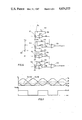
FIG. 3 is a side view of an embodiment of an optical rotary encoder of the present invention;
FIG. 4 is a plan view of an essential part of the optical rotary encoder of FIG. 3;
FIG. 5 is a waveform chart for explaining an operational mode of the optical rotary encoder of FIGS. 2, 3 and 4;
FIG. 6 is a circuit diagram of a detection circuit included in the optical rotary encoder of FIG. 3; and
FIG. 7 is a waveform chart for explaining another operational mode of the optical rotary encoder of FIG. 3.
DESCRIPTION OF THE PREFERRED EMBODIMENTS
FIG. 1 shows an example of arrangement of photodiodes in the conventional optical rotary encoder. The optical rotary encoder generally includes a slit plate 10 mounted on a rotating shaft. The slit plate 10 is provided with a plurality of circumferentially aligned slits 101, 102, - - - . A light emitting element (not shown in FIG. 1) is disposed at one side of the slit plate 10. A plurality of photodiodes 20 are disposed at the opposite side of the slit plate 10 so that the photodiodes 20 periodically receive the light beam emitted from the light emitting element as the slit plate 10 rotates. Output signals derived from the photodiodes 20 are applied to a detection circuit to determine the angular position and velocity of the rotating shaft.
The photodiodes 20 in the conventional optical rotary encoder include a first photodiode 201 and a second photodiode 202, which are offset from each other in the tangential direction by a distance equal to one half of the width of the slit 101 (102, - - - ) so as to develop output signals, one signal leading or lagging the other by 90° depending on the direction of rotation of the shaft. The photodiodes 20 further include a third photodiode 203 for compensating for variations in the intensity of the light beam emitted from the light emitting element. That is, the third photodiode 203 functions as a monitor sensor. The locations of the first through third photodiodes 20 are precisely determined by a mask disposed on the light receiving surface.
The conventional optical rotary encoder of the type shown in FIG. 1 occupies a considerably large size because the photodiodes 20 are separated from each other in the radial direction of the slit plate 10. Furthermore, an accurate detection is ensured only when the locations of the first and second photodiodes 201 and 202 are precisely adjusted with respect to the location of the slit 101 (102, - - - ) on the slit plate 10. Moreover, even when the first and second photodiodes 201 and 202 have the same size, the amount of the light beam impinging on the first photodiode 201 is greater than that impinging on the second photodiode 202 because the two photodiodes 201 and 202 are aligned along the radial direction of the elongated slit 101 (102, - - - ). This complicates the adjustment of the signal level developed from the first and second photodiodes 201 and 202.
FIG. 2 shows arrangement of photodiodes in an embodiment of an optical rotary encoder of the present invention. Like elements corresponding to those of FIG. 1 are indicated by like numerals.
Four photodiodes 30 are aligned in the tangential direction of the slit plate 10 within one pitch of the slits 101, 102, - - - . More specifically, the four photodiodes 30 are aligned with the interval of 1/4 pitch, and the four photodiodes 30 are formed on a common single semiconductor substrate and are electrically separated from each other. That is, the four photodiodes 30 comprise a first photodiode 301, a second photodiode 302, a third photodiode 303 and a fourth photodiode 304.
FIG. 3 schematically shows the construction of the optical rotary encoder of the present invention. Like elements corresponding to those of FIG. 2 are indicated by like numerals. The slit plate 10 is secured to a rotating shaft 12 of a motor 14. The optical rotary encoder of the present invention includes a light emitting section 16 and a light responsive section 18, which, in combination, substantially sandwich the slit plate 10. The light emitting section 16 includes a light emitting diode 160. The light responsive section 18 includes the above-mentioned four photodiodes 30.
FIG. 4 schematically shows the light responsive section 18. As already discussed above, the first through fourth photodiodes 301, 302, 303 and 304 are formed on a common single semiconductor substrate 40. A detection circuit 50, to which the output signals of the first through fourth photodiodes 301, 302, 303 and 304 are applied, is formed on the common single semiconductor substrate 40.
In response to the rotation of the slit plate 10, each of the photodiodes 301, 302, 303 and 304 is periodically exposed to the light beam emitted from the light emitting diode 160. The actual size S1 of the light receiving surface of the first photodiode 301 varies as shown in FIG. 5. The actual size S2 of the light receiving surface of the second photodiode 302 varies as shown in FIG. 5. The actual sizes S3 and S4 of the light receiving surfaces of the third and fourth photodiodes 303 and 304 vary, respectively, as shown in FIG. 5. Since the four photodiodes 30 are aligned with the interval of 1/4 pitch, the variations of the actual sizes of the light receiving surfaces are offset by 1/4 pitch. More specifically, the variation of the actual size S1 of the first photodiode 301 leads or lags the variation of the actual size S2 of the second photodiode 302 by 90° depending on the direction of rotation of the shaft 12. The variation of the actual size S1 of the first of the first photodiode 301 leads or lags the variation of the actual size S3 of the third photodiode 303 by 180° depending on the direction of the rotation of the shaft 12. The variation of the actual size S1 of the first photodiode 301 leads or lags the variation of the actual size S4 of the fourth photodiode 304 by 270° depending on the direction of the rotation of the shaft 12.
FIG. 6 shows the construction of the detection circuit 50. In response to the variations of the actual sizes S1 through S4, each of the photodiodes 301 through 304 generates optoelectric current IS1, IS2, IS3 and IS4, respectively, which is proportional to the actual sizes S1 through S4 of the light receiving surfaces. Each of the thus generated optoelectric currents IS1, IS2, IS3 and IS4 is applied to one of operation amplifiers 501(OP1), 502(OP2), 503(OP3) and 504(OP4). When the resistance value of a feedback resistor 511 of the operation amplifier 501(OP1) is r1, an output voltage VA of the operation amplifier 501(OP1) is represented as follows.
V.sub.A =r.sub.1 ×IS.sub.1
When the resistance value of a feedback resistor 512 of the operation amplifier 502(OP2) is r2, an output voltage VB of the operation amplifier 502(OP2) is represented as follows.
V.sub.B =r.sub.2 ×IS.sub.2
The output voltage VA leads or lags the output voltage VB by 90° depending on the direction of the rotation of the shaft 12 as shown in FIG. 5. When the resistance value of a feedback resistor 513 of the operation amplifier 503(OP3) is r3, an output voltage VA of the operation amplifier 503(OP3) is represented as follows.
V.sub.A =r.sub.3 ×IS.sub.3
The output voltage VA of the operation amplifier 501(OP1) leads or lags the output voltage VA of the operation amplifier 503(OP3) by 180° depending on the direction of the rotation of the shaft 12 as shown in FIG. 5. When the resistance value of a feedback resistor 514 of the operation amplifier 504(OP4) is r4, an output voltage VB of the operation amplifier 504(OP4) is represented as follows.
V.sub.B =r.sub.4 ×IS.sub.4
The output voltage V4 of the operation amplifier 501(OP1) leads or lags the output voltage VB of the operation amplifier 504(OP4) by 270° depending on the direction of the rotation of the shaft 12 as shown in FIG. 5.
The output voltage VA of the operation amplifier 501(OP1), and the output voltage VA of the operation amplifier 503(OP3) are applied to a first comparator 521. When the level of the output voltage VA developed from the operation amplifier 501(OP1) is greater than the level of the output voltage VA of the operation amplifier 503(OP3), an output signal VoutA of the first comparator 521 bears the logic high as shown in FIG. 5. If the output voltage VA of the operation amplifier 501(OP1) is lower than the output voltage VA of the operation amplifier 503(OP3), the output signal VoutA bears the logic low as shown in FIG. 5. The output voltage VB of the operation amplifier 504(OP4), and the output voltage VB of the operation amplifier 502(OP2) are applied to a second comparator 522. When the level of the output voltage VB developed from the operation amplifier 504(OP4) is higher than the level of the output voltage VB of the operation amplifier 502(OP2), an output signal VoutB of the second comparator 522 bears the logic high as shown in FIG. 5. Contrarily, when the output voltage VB of the operation amplifier 504(OP4) is lower than the output voltage VB of the operation amplifier 502(OP2), the output signal VoutB bears the logic low as shown in FIG. 5. The thus obtained two output signals VoutA and VoutB are offset by 90°and are utilized to obtain information regarding the angular position and velocity of the rotating shaft 12.
When the intensity of the light beam emitted from the light emitting diode 160 becomes small, the voltage level of the output voltages VA, VA, VB and VB becomes small. FIG. 7 shows the reduced output voltages VA' and VA'. It will be clear from FIG. 7 that the output signals VoutA and VoutB do not change even when the intensity of the light beam emitted from the light emitting diode 160 varies. That is, the detection circuit of FIG. 6 functions to compensate for the variations in the characteristics of the light emitting element and the light responsive elements.
The invention being thus described, it will be obvious that the same may be varied in many ways. Such variations are not to be regarded as a departure from the spirit and scope of the invention, and all such modifications are intended to be included within the scope of the following claims.

Claims (12)

What is claimed is:
1. An optical rotary encoder comprising: a slit plate secured to a rotating shaft, said slit plate having a plurality of circumferentially aligned slits with a predetermined pitch (P);
light emitting means for emitting a light beam toward said slit plate;
light responsive means for receiving said light beam emitted from said light emitting means after said light beam is modulated by said slits in response to rotation of said slit plate and for developing output signals related thereto;
detection circuit means for determining the angular position and velocity of said rotating shaft in accordance with said output signals developed by said light responsive means;
said light responsive means comprising first, second, third and fourth light responsive elements aligned in the tangential direction of said slit plate and being spaced at a predetermined interval which corresponds to 1/4 said predetermined pitch (P), each of said elements developing a said output signal electrically independent from said output signals developed by the other of said elements;
said detection circuit means including means for developing first and second phase quadrature related relative position signals from said output signals developed by said first, second, third and fourth light responsive elements while canceling variations in said output signals caused by variations in the intensity of said light beam as received by said light responsive elements.
2. The optical rotary encoder of claim 1, wherein said four light responsive elements are formed on a common single semiconductor substrate.
3. The optical rotary encoder of claim 2, wherein said detection circuit means is also formed on said common single semiconductor substrate.
4. An optical rotary encoder comprising: a slit plate secured to a rotating shaft, said slit plate having a plurality of circumferentially aligned slits with a predetermined pitch (P);
a light emitting diode disposed at one side of said slit plate;
a plurality of photodiodes, formed on a single semiconductor substrate, disposed at the opposite side of said slit plate and developing output signals related to the intensity of light received from said light emitting diode; and
detection circuit means for determining the angular position and velocity of said rotating shaft in accordance with said output signals developed by said plurality of photodiodes;
said light responsive means comprising first, second, third and fourth photodiodes aligned in the tangential direction of said slit plate at a predetermined interval which corresponds to 1/4 said predetermined pitch (P), each of said photodiodes developing a said output signal electrically independent from said output signals developed by the other of said photodiodes;
said detection circuit means including means for developing first and second phase quadrature related relative position signals from said output signals developed by said first, second, third and fourth photodiodes while canceling variations in said output signal caused by variations in the intensity of said light beam as received by said photodiodes.
5. The optical rotary encoder of claim 11, wherein said detection circuit means comprises:
a first amplifying circuit connected to said first photodiode;
a second amplifying circuit connected to said second photodiode;
a third amplifying circuit connected to said third photodiode; and
a fourth amplifying circuit connected to said fourth photodiode;
said first means for comparing including a first comparator for comparing levels of signals developed from said first amplifying circuit and said third amplifying circuit;
said second means for comparing including a second comparator for comparing levels of signals developed from said fourth amplifying circuit and said second amplifying circuit.
6. The optical rotary encoder of claim 5, wherein said detection circuit means is also formed on said single semiconductor substrate.
7. The encoder of claim 1 wherein said means for developing cancels said variations in said output signals without varying the drive voltage to said light emitting means.
8. The encoder of claim 1 wherein said means for developing includes,
first means for comparing said output signals developed by said first and third light responsive elements to develop said first relative position signal, and
second means for comparing said output signals developed by said second and fourth light responsive elements to develop said second relative position signals,
said first and second means for comparing cancelling out timing variations in said output signals caused by variations in the intensity of said light beam.
9. The encoder of claim 8 wherein said first and second means for comparing compensate for variations in output signal strength caused by variations in the intensity of said light beam by developing said relative position signals as square waves having a constant voltage at each level thereof.
10. The encoder of claim 1 wherein said means for developing cancels said variations in said output signals without varying the drive voltage to said light emitting diode.
11. The encoder of claim 4 wherein said means for developing includes,
first means for comparing said output signals developed by said first and third photodiodes to develop said first relative position signal, and
second means for comparing said output signals developed by said second and fourth photodiodes to develop said second relative position signal,
said first and second means for comparing cancelling out timing variations in said output signals caused by variations in the intensity of said light beam.
12. The encoder of claim 11 wherein said first and second means for comparing compensate for variations in output signal strength caused by variations in the intensity of said light beam by developing said relative position signals as square waves having a constant voltage at each level thereof.
US06/521,933 1982-08-31 1983-08-10 Optical rotary encoder Expired - Lifetime US4654525A (en)

Applications Claiming Priority (4)

Application Number Priority Date Filing Date Title
JP13257682U JPS5935821U (en) 1982-08-31 1982-08-31 Photoelectric rotary encoder
JP57-132576[U] 1982-08-31
JP57152014A JPS5940258A (en) 1982-08-31 1982-08-31 Photoelectric type rotary encoder
JP57-152014 1982-08-31

Publications (1)

Publication Number Publication Date
US4654525A true US4654525A (en) 1987-03-31

Family

ID=26467119

Family Applications (1)

Application Number Title Priority Date Filing Date
US06/521,933 Expired - Lifetime US4654525A (en) 1982-08-31 1983-08-10 Optical rotary encoder

Country Status (3)

Country Link
US (1) US4654525A (en)
EP (1) EP0102241B1 (en)
DE (1) DE3380038D1 (en)

Cited By (20)

* Cited by examiner, † Cited by third party
Publication number Priority date Publication date Assignee Title
US4767925A (en) * 1985-12-28 1988-08-30 Aisin-Warner Kabushiki Kaisha Optical type relative rotation measurement apparatus
US4767215A (en) * 1986-06-09 1988-08-30 Ateoq Corporation Lens characterization apparatus and method
US4833316A (en) * 1985-09-05 1989-05-23 Sharp Kabushiki Kaisha Rotary encoder
US4982085A (en) * 1988-09-20 1991-01-01 La Chaux De Fonds Incremental optical encoder with radiation regulation means
US5148020A (en) * 1991-04-17 1992-09-15 Hewlett-Packard Company Optical encoder with photodetectors of width equal to and one-half of code wheel's window and spoke width
US5543821A (en) * 1991-04-05 1996-08-06 Logitech, Inc. Track ball mounted on keyboard
DE19843176C1 (en) * 1998-09-21 2000-10-19 Siemens Ag Optical encoder for the detection of rotary and linear movements
DE19963809A1 (en) * 1999-12-30 2001-07-19 Osram Opto Semiconductors Gmbh Optical encoder to detect linear or rotational movement; has grid unit with equal length transparent and opaque areas and detection unit with three photodiodes parallel to grid unit
USRE37878E1 (en) 1992-08-10 2002-10-15 Logitech Europe, S.A. Pointing device with differential optomechanical sensing
CN1109960C (en) * 1995-11-10 2003-05-28 任天堂株式会社 Joystick apparatus
US6590201B2 (en) * 1999-12-22 2003-07-08 Rohm Co., Ltd. Optical encoder incorporating linear light controlling member
US20030189164A1 (en) * 2002-01-17 2003-10-09 Capella Microsystems, Inc. Photodetection system and circuit for amplification
US6653619B2 (en) 2000-09-15 2003-11-25 Agilent Technologies, Inc. Optical motion encoder with a reflective member allowing the light source and sensor to be on the same side
US20050051715A1 (en) * 2003-08-08 2005-03-10 Sharp Kabushiki Kaisha Optical encoder
WO2005106397A1 (en) * 2004-04-28 2005-11-10 Preh Gmbh Rotating actuator
US20080054170A1 (en) * 2006-08-29 2008-03-06 Sharp Kabushiki Kaisha Optical encoder and electronic equipment using the same
US20080283736A1 (en) * 2007-05-17 2008-11-20 Norikazu Okada Optical encoder and electronic equipment having the same
US20090008537A1 (en) * 2007-07-05 2009-01-08 Tadamasa Kimura Optical encoder and electronic equipment
US20100301195A1 (en) * 2009-05-31 2010-12-02 Avago Technologies Ecbu (Singapore) Pte. Ltd. High Resolution Single Track Optical Encoder
US20120069323A1 (en) * 2010-09-16 2012-03-22 Canon Kabushiki Kaisha Displacement measuring apparatus

Families Citing this family (7)

* Cited by examiner, † Cited by third party
Publication number Priority date Publication date Assignee Title
DE3510651A1 (en) * 1985-03-23 1986-09-25 Robert Bosch Gmbh, 7000 Stuttgart INCREMENTAL GUIDE
IT1184495B (en) * 1985-04-26 1987-10-28 Michele Merlo INCORRECTED VERNIER OPTICAL CODER (ENCODER)
FR2583544B1 (en) * 1985-06-14 1987-09-04 Mcb OPTICAL CODE READING DEVICE, ESPECIALLY OF THE FULLY INTEGRATED TYPE
CH680696B5 (en) * 1989-11-03 1993-04-30 Rolex Montres
US4952799A (en) 1989-03-10 1990-08-28 Hewlett-Packard Company Reflective shaft angle encoder
DE19818654A1 (en) * 1998-04-25 1999-11-04 Hengstler Gmbh Sensor unit for encoder systems
KR101239592B1 (en) * 2011-05-11 2013-03-05 박성일 Apparatus for stripping floor coverings having clitch devices

Citations (8)

* Cited by examiner, † Cited by third party
Publication number Priority date Publication date Assignee Title
US3304434A (en) * 1965-06-01 1967-02-14 Bunker Ramo Position control system employing pulse producing means indicative of magnitude and direction of movement
US3709611A (en) * 1971-03-03 1973-01-09 Sopelem Apparatus for deriving electrical signals
US3757128A (en) * 1972-03-20 1973-09-04 Ibm Multiphase tachometer
US3809895A (en) * 1971-10-13 1974-05-07 J Taisne Systems for measuring displacements
US4097150A (en) * 1976-07-23 1978-06-27 Pitney-Bowes, Inc. Optical detection weighing system
US4118129A (en) * 1974-07-01 1978-10-03 Qume Corporation Rotary wheel printing system
US4152579A (en) * 1977-12-27 1979-05-01 Pitney-Bowes, Inc. Digital tracking system with analog signal resolution
US4496835A (en) * 1981-06-15 1985-01-29 Ing. C. Olivetti & C., S.P.A. Shaft encoder with diffusely placed light sensitive elements

Family Cites Families (2)

* Cited by examiner, † Cited by third party
Publication number Priority date Publication date Assignee Title
US4224514A (en) * 1978-06-16 1980-09-23 Sensor Technology, Inc. Optical encoder
DE3007311C2 (en) * 1980-02-27 1985-11-28 Dr. Johannes Heidenhain Gmbh, 8225 Traunreut Digital photoelectric length or angle measuring system

Patent Citations (8)

* Cited by examiner, † Cited by third party
Publication number Priority date Publication date Assignee Title
US3304434A (en) * 1965-06-01 1967-02-14 Bunker Ramo Position control system employing pulse producing means indicative of magnitude and direction of movement
US3709611A (en) * 1971-03-03 1973-01-09 Sopelem Apparatus for deriving electrical signals
US3809895A (en) * 1971-10-13 1974-05-07 J Taisne Systems for measuring displacements
US3757128A (en) * 1972-03-20 1973-09-04 Ibm Multiphase tachometer
US4118129A (en) * 1974-07-01 1978-10-03 Qume Corporation Rotary wheel printing system
US4097150A (en) * 1976-07-23 1978-06-27 Pitney-Bowes, Inc. Optical detection weighing system
US4152579A (en) * 1977-12-27 1979-05-01 Pitney-Bowes, Inc. Digital tracking system with analog signal resolution
US4496835A (en) * 1981-06-15 1985-01-29 Ing. C. Olivetti & C., S.P.A. Shaft encoder with diffusely placed light sensitive elements

Cited By (31)

* Cited by examiner, † Cited by third party
Publication number Priority date Publication date Assignee Title
US4833316A (en) * 1985-09-05 1989-05-23 Sharp Kabushiki Kaisha Rotary encoder
US4767925A (en) * 1985-12-28 1988-08-30 Aisin-Warner Kabushiki Kaisha Optical type relative rotation measurement apparatus
US4767215A (en) * 1986-06-09 1988-08-30 Ateoq Corporation Lens characterization apparatus and method
US4982085A (en) * 1988-09-20 1991-01-01 La Chaux De Fonds Incremental optical encoder with radiation regulation means
US5543821A (en) * 1991-04-05 1996-08-06 Logitech, Inc. Track ball mounted on keyboard
US5148020A (en) * 1991-04-17 1992-09-15 Hewlett-Packard Company Optical encoder with photodetectors of width equal to and one-half of code wheel's window and spoke width
USRE37878E1 (en) 1992-08-10 2002-10-15 Logitech Europe, S.A. Pointing device with differential optomechanical sensing
CN1109960C (en) * 1995-11-10 2003-05-28 任天堂株式会社 Joystick apparatus
US6313460B1 (en) 1998-09-21 2001-11-06 Siemens Aktiengesellschaft Optical encoder for detecting rotary and linear movements
US6552329B2 (en) 1998-09-21 2003-04-22 Osram Opto Semi-Conductors Gmbh Co. Ohg Method for a quantitative detection of a linear and rotary movement
DE19843176C1 (en) * 1998-09-21 2000-10-19 Siemens Ag Optical encoder for the detection of rotary and linear movements
US6590201B2 (en) * 1999-12-22 2003-07-08 Rohm Co., Ltd. Optical encoder incorporating linear light controlling member
DE19963809C2 (en) * 1999-12-30 2002-01-17 Osram Opto Semiconductors Gmbh Optical encoder with triple photodiode
DE19963809A1 (en) * 1999-12-30 2001-07-19 Osram Opto Semiconductors Gmbh Optical encoder to detect linear or rotational movement; has grid unit with equal length transparent and opaque areas and detection unit with three photodiodes parallel to grid unit
US6797940B2 (en) 1999-12-30 2004-09-28 Osram Opto Semiconductors Gmbh & Co. Ohg Optical encoder with triple photodiode
US6653619B2 (en) 2000-09-15 2003-11-25 Agilent Technologies, Inc. Optical motion encoder with a reflective member allowing the light source and sensor to be on the same side
US20030189164A1 (en) * 2002-01-17 2003-10-09 Capella Microsystems, Inc. Photodetection system and circuit for amplification
US6838654B2 (en) 2002-01-17 2005-01-04 Capella Microsystems, Inc. Photodetection system and circuit for amplification
WO2004003481A1 (en) * 2002-01-17 2004-01-08 Capella Microsystems, Inc. Photodetection system and circuit for amlification
US20050051715A1 (en) * 2003-08-08 2005-03-10 Sharp Kabushiki Kaisha Optical encoder
US7223963B2 (en) * 2003-08-08 2007-05-29 Sharp Kabushiki Kaisha Optical encoder
WO2005106397A1 (en) * 2004-04-28 2005-11-10 Preh Gmbh Rotating actuator
US7589317B2 (en) 2006-08-29 2009-09-15 Sharp Kabushiki Kaisha Optical encoder having lens integrally molded with housing
US20080054170A1 (en) * 2006-08-29 2008-03-06 Sharp Kabushiki Kaisha Optical encoder and electronic equipment using the same
US20080283736A1 (en) * 2007-05-17 2008-11-20 Norikazu Okada Optical encoder and electronic equipment having the same
US20090008537A1 (en) * 2007-07-05 2009-01-08 Tadamasa Kimura Optical encoder and electronic equipment
US7820957B2 (en) 2007-07-05 2010-10-26 Sharp Kabushiki Kaisha Optical encoder for detecting movement of a moving object and electronic equipment including the optical encoder
US20100301195A1 (en) * 2009-05-31 2010-12-02 Avago Technologies Ecbu (Singapore) Pte. Ltd. High Resolution Single Track Optical Encoder
US8097842B2 (en) * 2009-05-31 2012-01-17 Avago Technologies Ecbu Ip (Singapore) Pte. Ltd. High resolution single track optical encoder
US20120069323A1 (en) * 2010-09-16 2012-03-22 Canon Kabushiki Kaisha Displacement measuring apparatus
US9116163B2 (en) * 2010-09-16 2015-08-25 Canon Kabushiki Kaisha Displacement measuring apparatus

Also Published As

Publication number Publication date
EP0102241B1 (en) 1989-06-07
EP0102241A3 (en) 1985-10-16
EP0102241A2 (en) 1984-03-07
DE3380038D1 (en) 1989-07-13

Similar Documents

Publication Publication Date Title
US4654525A (en) Optical rotary encoder
US4224514A (en) Optical encoder
US4319134A (en) Optical encoder
US4037157A (en) Electro-optical speed transducer
US4621256A (en) Apparatus for measuring rate of angular displacement
US3885872A (en) Digital proximity sensing system
US4649267A (en) Automatic gain control circuit for encoder
US4761546A (en) Optical displacement measuring system with nonlinearity correction
GB2176616A (en) Magnetic field responsive device for measuring rotation
US4160200A (en) Servo control apparatus
US5243187A (en) High resolution absolute encoder for position measurement
US4654636A (en) Displacement measuring apparatus
JPS5940258A (en) Photoelectric type rotary encoder
US4593269A (en) Compact optional rotary encoder having adjustable light admitting and receiving components
US4488813A (en) Reflectivity compensating system for fiber optic sensor employing dual probes at a fixed gap differential
US10955266B2 (en) Light detector employing trapezoidal chips
US4152579A (en) Digital tracking system with analog signal resolution
US4673810A (en) Increment sensing with three beam mark detection
CA1051549A (en) Arrangement for aligning the image of an information structure on a converter
US4219276A (en) Detection system for ring laser gyro
US4309103A (en) Device for contact-free thickness or interval measurement
US4710622A (en) Device for stabilizing photosensor output to varying temperature
US6184677B1 (en) Motion sensor having a timer and a switch for measuring absolute field strength
JP3160372B2 (en) Rotation angle detector
JPS6156912A (en) Optoelectric rotary encoder

Legal Events

Date Code Title Description
AS Assignment

Owner name: SHARP KABUSHIKI KAISHA, 22-22 NAGAIKE-CHO, ABENO-K

Free format text: ASSIGNMENT OF ASSIGNORS INTEREST.;ASSIGNORS:EBINA, KIYOSHI;NAKAO, KAZUHIRA;TANI, ZEMPEI;REEL/FRAME:004162/0907

Effective date: 19830802

STCF Information on status: patent grant

Free format text: PATENTED CASE

FEPP Fee payment procedure

Free format text: PAYOR NUMBER ASSIGNED (ORIGINAL EVENT CODE: ASPN); ENTITY STATUS OF PATENT OWNER: LARGE ENTITY

FPAY Fee payment

Year of fee payment: 4

FEPP Fee payment procedure

Free format text: PAYOR NUMBER ASSIGNED (ORIGINAL EVENT CODE: ASPN); ENTITY STATUS OF PATENT OWNER: LARGE ENTITY

FPAY Fee payment

Year of fee payment: 8

FEPP Fee payment procedure

Free format text: PAYER NUMBER DE-ASSIGNED (ORIGINAL EVENT CODE: RMPN); ENTITY STATUS OF PATENT OWNER: LARGE ENTITY

Free format text: PAYOR NUMBER ASSIGNED (ORIGINAL EVENT CODE: ASPN); ENTITY STATUS OF PATENT OWNER: LARGE ENTITY

FPAY Fee payment

Year of fee payment: 12