US4638326A - Ink jet recording apparatus - Google Patents
Ink jet recording apparatus Download PDFInfo
- Publication number
- US4638326A US4638326A US06/834,813 US83481386A US4638326A US 4638326 A US4638326 A US 4638326A US 83481386 A US83481386 A US 83481386A US 4638326 A US4638326 A US 4638326A
- Authority
- US
- United States
- Prior art keywords
- ink
- excitation voltage
- voltage value
- value
- ink droplet
- Prior art date
- Legal status (The legal status is an assumption and is not a legal conclusion. Google has not performed a legal analysis and makes no representation as to the accuracy of the status listed.)
- Expired - Lifetime
Links
Images


Classifications
-
- B—PERFORMING OPERATIONS; TRANSPORTING
- B41—PRINTING; LINING MACHINES; TYPEWRITERS; STAMPS
- B41J—TYPEWRITERS; SELECTIVE PRINTING MECHANISMS, i.e. MECHANISMS PRINTING OTHERWISE THAN FROM A FORME; CORRECTION OF TYPOGRAPHICAL ERRORS
- B41J2/00—Typewriters or selective printing mechanisms characterised by the printing or marking process for which they are designed
- B41J2/005—Typewriters or selective printing mechanisms characterised by the printing or marking process for which they are designed characterised by bringing liquid or particles selectively into contact with a printing material
- B41J2/01—Ink jet
- B41J2/07—Ink jet characterised by jet control
- B41J2/115—Ink jet characterised by jet control synchronising the droplet separation and charging time
-
- B—PERFORMING OPERATIONS; TRANSPORTING
- B41—PRINTING; LINING MACHINES; TYPEWRITERS; STAMPS
- B41J—TYPEWRITERS; SELECTIVE PRINTING MECHANISMS, i.e. MECHANISMS PRINTING OTHERWISE THAN FROM A FORME; CORRECTION OF TYPOGRAPHICAL ERRORS
- B41J2/00—Typewriters or selective printing mechanisms characterised by the printing or marking process for which they are designed
- B41J2/005—Typewriters or selective printing mechanisms characterised by the printing or marking process for which they are designed characterised by bringing liquid or particles selectively into contact with a printing material
- B41J2/01—Ink jet
- B41J2/015—Ink jet characterised by the jet generation process
- B41J2/02—Ink jet characterised by the jet generation process generating a continuous ink jet
- B41J2/03—Ink jet characterised by the jet generation process generating a continuous ink jet by pressure
- B41J2002/033—Continuous stream with droplets of different sizes
Definitions
- the present invention relates to an ink jet recording apparatus, and in particular to the control of the ink droplets generation in an ink jet recording apparatus which alternately separates the leading edge of the columnar ink stream ejected from the nozzle into ink droplets of large diameter and small diameter and surely charges and deflects those ink droplets independently of each other to record images.
- An ink jet recording apparatus whereto the present invention is applied is the ink jet recording apparatus of the type as described in U.S. Pat. No. 4,050,077 by Takahiro Yamada and Tetsuo Doi.
- ink droplets of large diameter and ink droplets of small diameter are alternately generated, and these droplets are charged and deflected according to recording signals to control the impingement of the ink droplets against the recording sheet.
- such an ink jet recording apparatus In order to attain the favorable recording at all times even if the ambient temperature of the recording apparatus or the property of the ink is changed, such an ink jet recording apparatus must be provided with a device for automatically setting such a suitable excitation state of the nozzle that ink droplets of large diameter and ink droplets of small diameter are suitably generated at all times.
- ink droplets of small diameter are sometimes charged by the recording signals for charging the ink droplets of large diameter. Accordingly, ink droplets of small diameter are sometimes deflected largely, resulting in largely disturbed recording.
- An object of the present invention is to provide an ink jet recording apparatus which is equipped with a device for automatically setting the production state of ink droplets at the optimum value at all times, which is able to surely control the charging of ink droplets of large diameter and ink droplets of small diameter by means of their respective recording signals, and which is able to favorably record information even if the ambient temperature of the recording apparatus or the property of the ink is changed.
- the present invention relates to an ink jet recording apparatus wherein ink is introduced into an excited nozzle and separated at the nozzle alternately into ink droplets of large diameter and ink droplets of small diameter, and wherein those ink droplets are ejected toward a substance to be recorded thereon and are charged and deflected according to record signals so as to impinge against predetermined positions of the recording medium.
- an ink jet recording apparatus includes a record condition optimizing device for setting the excitation voltage of the nozzle optimumly to ensure the generation and charging of ink droplets.
- the record condition optimizing device includes first means for sweeping the excitation voltage on the logarithmic scale, second means for successively detecting an excitation voltage value which causes an ink droplet of large diameter to be separated from the columnar ink stream and generated at a phase ⁇ k , and an excitation voltage value which causes an ink droplet of small diameter to be separated from the columnar ink stream and generated at the phase ⁇ k , and third means for, on the basis of the results detected by the second means, calculating a space Wn on the logarithmic scale between an excitation voltage value Vn generating an ink droplet of small diameter and an excitation voltage value Vn generating an ink droplet of large diameter which is adajacent to and lower than the excitation voltage value vn, calculating a space wn on the logarithmic scale between the excitation voltage value vn generating an ink droplet of small diameter and an excitation voltage value Vn+1 generating an ink droplet of large
- An ink jet recording apparatus includes a record condition optimizing device for properly setting the ink droplet generating state as follows.
- the record condition optimizing device sweeps the excitation voltage value of the nozzle on the logarithmic scale and successively measures the voltage values causing ink droplets of large diameter and ink droplets of small diameter to be separated from the columnar ink stream at the phase ⁇ k .
- the device calculates a space Wn between an excitation voltage value vn generating an ink droplet of small diameter and an excitation voltage value Vn generating an ink droplet of large diameter which is adjacent to and lower than the excitation voltage value vn.
- the device also calculates a space wn between the excitation voltage value vn generating an ink droplet of small diameter and an excitation voltage value Vn+1 generating an ink droplet of large diameter which is adjacent to and higher than the excitation voltage value vn. Further, the record condition optimizing device calculates the value of
- the sweeping excitation voltage with the logarithmic scale may be compensatated in some part of the sweeping scale in consideration of the shape of nozzle or distortion of excitation voltage. Therefore, the comensated part is not completely coincide with the logarithmic scale. However, such compensation is depend on the actual cases.
- the meaning of the term logarithmic scale includes substantial logarithmic scale at the case of voltage compensation.
- FIG. 1 is a block diagram of an embodiment of an ink jet recording apparatus according to the present invention.
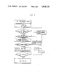
- FIG. 2 is a flow chart for illustrating the operation of the apparatus shown in FIG. 1.
- FIG. 3 is a time chart for illustrating the generation of ink droplets.
- FIG. 4 is a diagram for illustrating the calculation of a value
- FIG. 5 is a diagram for illustrating the phase difference between generation of ink droplets of large diameter and generation of ink droplets of small diameter.
- FIG. 6 is a diagram for illustrating the application of the recording signal voltage used to charge ink droplets.
- FIG. 7 is a flow chart for illustrating the operation of another embodiment of the present invention.
- FIG. 8 is a block diagram of another embodiment of an ink jet recording apparatus according to the present invention.
- FIG. 9 is a flow chart for illustrating the operation of the apparatus shown in FIG. 8.
- a nozzle 1 an ink droplet of large diameter 2, an ink droplet of small diameter 3, a columnar ink stream 4, a control and calculation unit 5, a D/A converter 6, a sine wave exciter 7, a multiplier 8, an excitation amplifier 9, a test signal generating circuit 11, control electrodes 12a and 12b, an induced current sensing circuit 13, an A/D converter 14, a record charging signal generating circuit 15, a charging signal changeover circuit 16, a video amplifier 17, and an electrode changeover circuit 18 are shown.
- Blocks A, B and C represent variable excitation voltage means, ink droplet generating voltage measuring means, and optimum excitation voltage value determining means, respectively.
- the record condition optimizing device in this embodiment includes variable excitation voltage means A which is the first means for sweeping on the logarithmic scale the value of the excitation voltage applied to the nozzle 1 having a piezoelectric device attached thereto, ink droplet generating voltage measuring means B which is the second means for successively measuring excitation voltage values which cause an ink droplet of large diameter 2 and an ink droplet of small diameter 3 alternately separated from the columnar ink stream 4 to have a phase ⁇ k , and optimum excitation voltage value determining means C which is the third means for, on the basis of the results measured by the second means, carrying out calculation and judgment to find the optimum excitation voltage value and set the excitation voltage at its optimum value.
- the partition of the ink jet apparatus into these blocks is illustrated in FIG. 1.
- FIG. 1 The operation of the ink jet apparatus of FIG. 1 will now be described by referring to a flow chart of FIG. 2 as well as FIGS. 3 to 6.
- step 201 the control and calculation unit 5 makes the test signal generating circuit 11 produce a test signal (b) shown in FIG. 3 having a narrow width and phase ⁇ k which is in fixed relation with respect to the phase of the excitation waveform (excitation voltage waveform) (a).
- the test signal (b) is applied to the control electrode 12a via the charging signal changeover circuit 16, video amplifier 17, and electrode changeover circuit 18.
- step 202 the excitation voltage Ve for exciting the nozzle 1 is initialized to the minimum value Vemin over the sweep range. This initialization is carried out by supplying the command value from the control and calculation unit 5 composed of a microcomputer to the D/A converter 6 and by multiplying the command value with the sine wave supplied from the sine wave exciter 7 in the multiplier 8.
- step 203 it is checked whether an ink droplet is generated or not at the
- step 203 the processing in step 203 is carried out again. If the generation of an ink droplet is detected in step 203, it is checked whether the ink droplet is an ink droplet of small diameter or not in step 205.
- FIG. 3(c) shows the ink droplet generation timing.
- ink droplets of large diameter are separated from the columnar ink stream to be generated.
- ink droplets of small diameter are separated from the columnar ink stream to be generated.
- Lines (c-1) to (c-4) of FIG. 3 correspond to states of different excitation voltage values.
- the lines (c-1) to (c-4) represent the generation phases of ink droplets. States such as a state in which only ink droplets of large diameter are generated from the columnar ink stream, or a state in which both ink droplets of large diameter and ink droplets of small diameter are generated, are represented by the lines (c-1) to (c-4).
- ink droplets of large diameter are generated in the ink droplet generation state (c-2), and ink droplets of small diameter are generated in the state (c-4).
- Ink droplets are not charged in the state (c-1) or (c-3).
- phase ⁇ k of the test signal Since the phase ⁇ k of the test signal is constant, it is possible to examine the excitation voltage value generating an ink droplet at the phase ⁇ k by examining the charged state of the ink droplet.
- ink droplets of large diameter are generated at the phase ⁇ k in the state (c-2), and ink droplets of small diameter are generated at the phase ⁇ k in the state (c-4).
- a test signal corresponding to, say, approximately 30 periods of excitation is generated at certain excitation voltage value to charge ink droplets generated within the duration of the test signal.
- the ink droplet thus charged let flow an induced current between a control electrode corresponding to the control electrode of this embodiment and the ground.
- the current is sensed by a circuit corresponding to the induced current sense circuit 13 to be converted into a voltage value Vd as illustrated in FIG. 1.
- the voltage value Vd can be detected with respect to the nozzle excitation voltage represented in logarithmic scale.
- a voltage value Vn for separating the ink droplet of large diameter from the columnar ink stream at the phase ⁇ k and a voltage value vn for separating the ink droplet of small diameter from the columnar ink stream at the phase ⁇ k can be obtained.
- the output of the induced current sensing circuit 13 is supplied to the control and calculation unit 5 via the A/D converter 14.
- the excitation voltage value indicating the peak of the voltage value is detected together with the height of the peak to detect Vn and vn.
- the excitation voltage at that time is stored in the memory as vn, and the processing in the next step 204 is carried out. If the ink droplet is not small diameter (i.e., in case of an ink droplet of large diameter), the voltage at that time is stored in the memory as Vn+1 in step 207, and it is checked in step 208 whether Vn has already been stored. If Vn has not been stored, Vn is replaced by Vn+1 in step 209, and the processing in step 204 is carried out. If Vn has already been stored, the processing in step 210 is carried out as described below.
- Wn and wn as illustrated in FIG. 4 are derived.
- the symbol Wn represents the space between the n-th excitation voltage value vn generating an ink droplet of small diameter and an excitation voltage value Vn generating an ink droplet of large diameter which is adjacent to and lower than vn.
- the symbol wn represents the space between vn and the excitation voltage value Vn+1 generating an ink droplet of large diameter which is adjacent to and higher than vn.
- is calculated.
- is stored with regard to vn in step 211.
- the abscissa of FIG. 5 represents the excitation voltage in logarithmic scale and the ordinate represents the phase.
- the solid line represents the change of the phase at which an ink droplet of large diameter is generated.
- the broken line represents the change of the phase at which an ink droplet of small diameter is generated.
- the generation phase of the ink droplets linearly varies with respect to the logarithm of the excitation voltage.
- ⁇ k (3/2) ⁇
- ink droplets of large diameter are generated at positions represented by symbols ⁇ o
- ink droplets of small diameter are generated at positions represented by symbols ⁇ . Since the excitation voltage value and the phase are respectively set at vn and ⁇ k by the processing already described, a point P illustrated in FIG. 5 has been established.
- phase of (1/2) ⁇ which is apart by ⁇ from the phase of (3/2) ⁇ is obtained when ink droplets are generated at positions represented by symbols and .
- Positions at which ink droplets of large diameter are generated around the above described point P are referred to as points Q, R and T as shown in FIG. 5.
- the triangle QRT is an isosceles triangle having the base QR. Accordingly, the point P is located approximately at the middle point between the point Q and the point R. Therefore, points P and T are located approximately on the line of the excitation voltage vn. And the phase difference between points P and T is approximately ⁇ .
- the record charging signal generating circuit 15 sends out its signal with timing as shown in (d) or (e) of FIG. 6.
- the record signal voltage for charging the ink droplet of large diameter is surely applied to the control electrodes 12a and 12b.
- the record signal voltage for charging the ink droplet of small diameter is surely applied to the control electrodes 12a and 12b.
- FIG. 6(d) shows the case where recording is carried out by using only ink droplets of small diameter
- FIG. 6(e) shows the case where recording is carried out by using both ink droplets of large diameter and ink droplets of small diameter.
- the charging signal changeover circuit 16 selects either the test signal or the record signal as the signal to be applied to the control electrodes 12a and 12b.
- the video amplifier 17 amplifies the charging signal.
- the electrode changeover circuit 18 connects the control electrode 12a to the video amplifier 17 to apply the test signal to the electrode 12a and connects the control electrode 12b to the induced current sensing circuit 13 to use the electrode 12b as the detection electrode for detecting the electric charge of the charged ink droplet.
- the electrode changeover circuit 18 connects both control electrodes 12a and 12b to the video amplifier 17 to apply the charging signal to those electrodes.
- the above described operation of the record condition optimizing device is automatically carried out with sufficiently high frequency before the recording begins and while the recording apparatus is not conducting the recording operation.
- the sweep range of excitation voltage is so set that the optimum excitation voltage value may be sufficiently located within the sweep range even if changes exist in ambient temperature, ink property, and nozzle excitation efficiency.
- are derived for all of the excitation voltage values within the sweep range from the minimum excitation voltage value Vemin to the maximum excitation voltage value Vemax. Then the excitation voltage value which minimizes the value of
- FIG. 7 shows a scheme according to another embodiment of the present invention.
- is successively derived and it is judged whether it is close to zero or not. If the value is close to zero, the excitation voltage is fixed at its value at that time without being changed up to Vemax.
- FIGS. 8 and 9 Another embodiment of a recording apparatus will now be described by referring to FIGS. 8 and 9.
- Reference numeral 10 denotes a signal phase changeover circuit.
- the apparatus of FIG. 8 differs from that of FIG. 1 in that the signal phase changeover circuit 10 is provided in the ink droplet generating voltage measuring circuit.
- the signal phase changeover circuit 10 is driven by a command supplied from the control and calculation unit 5.
- steps 901 and 902 the phase relation between the phases of the test signal and the record signal and the phase of the excitation waveform is successively changed over between two phases spaced apart by ⁇ , i.e., the phase ⁇ k and ⁇ k + ⁇ .
- the excitation voltage and phase are so set that the value
- can be set at a better value at phase (3/2) ⁇ than at phase (1/2) ⁇ .
- the generation state of ink droplets can always be set at the optimum value automatically as described above.
- an ink jet recording apparatus which is able to surely control the changing of each of ink droplets of large diameter and ink droplets of small diameter by the recording signal, and which is always able to carry out favorable recording even if the ambient temperature of the recording apparatus and the property of the ink are changed.
Landscapes
- Particle Formation And Scattering Control In Inkjet Printers (AREA)
Abstract
Wn=vn-Vn
wn=Vn-1-vn
Description
Claims (2)
Applications Claiming Priority (1)
| Application Number | Priority Date | Filing Date | Title |
|---|---|---|---|
| JP60041327A JPH0829590B2 (en) | 1985-03-04 | 1985-03-04 | Inkjet recording device |
Publications (1)
| Publication Number | Publication Date |
|---|---|
| US4638326A true US4638326A (en) | 1987-01-20 |
Family
ID=12605422
Family Applications (1)
| Application Number | Title | Priority Date | Filing Date |
|---|---|---|---|
| US06/834,813 Expired - Lifetime US4638326A (en) | 1985-03-04 | 1986-02-28 | Ink jet recording apparatus |
Country Status (4)
| Country | Link |
|---|---|
| US (1) | US4638326A (en) |
| EP (1) | EP0193916B1 (en) |
| JP (1) | JPH0829590B2 (en) |
| DE (1) | DE3671613D1 (en) |
Cited By (6)
| Publication number | Priority date | Publication date | Assignee | Title |
|---|---|---|---|---|
| FR2637844A1 (en) * | 1988-10-18 | 1990-04-20 | Imaje Sa | HIGH RESOLUTION PRINTING PROCESS USING SATELLITE INK DROPS USED IN A CONTINUOUS INK JET PRINTER |
| EP0390427A1 (en) * | 1989-03-31 | 1990-10-03 | Videojet Systems International, Inc. | Nozzle drive control system and method for ink jet printing |
| US5489929A (en) * | 1991-07-05 | 1996-02-06 | Imaje S.A. | Liquid-projection method and device for high-resolution printing in a continuous ink-jet printer |
| US5523778A (en) * | 1993-12-07 | 1996-06-04 | Videojet Systems International, Inc. | Segmented charge tunnel for drop charging in a printhead |
| EP1092542A1 (en) * | 1999-10-15 | 2001-04-18 | Imaje S.A. | Ink jet printer and printing process |
| US20080074449A1 (en) * | 2006-08-02 | 2008-03-27 | Lee Abraham P | Microfluidic production of monodispersed submicron emulsion through filtration and sorting of satellite drops |
Families Citing this family (1)
| Publication number | Priority date | Publication date | Assignee | Title |
|---|---|---|---|---|
| US5196860A (en) * | 1989-03-31 | 1993-03-23 | Videojet Systems International, Inc. | Ink jet droplet frequency drive control system |
Citations (4)
| Publication number | Priority date | Publication date | Assignee | Title |
|---|---|---|---|---|
| US4016571A (en) * | 1974-09-17 | 1977-04-05 | Hitachi, Ltd. | Ink jet recording apparatus |
| US4050077A (en) * | 1973-05-30 | 1977-09-20 | Hitachi, Ltd. | Liquid droplet supplying system |
| US4368474A (en) * | 1979-10-11 | 1983-01-11 | Sharp Kabushiki Kaisha | Ink droplet formation control in an ink jet system printer |
| US4524366A (en) * | 1983-05-20 | 1985-06-18 | Hitachi, Ltd. | Ink jet charge phasing apparatus |
Family Cites Families (4)
| Publication number | Priority date | Publication date | Assignee | Title |
|---|---|---|---|---|
| JPS5269628A (en) * | 1975-12-08 | 1977-06-09 | Hitachi Ltd | Ink jet recorder |
| JPS5933315B2 (en) * | 1980-03-10 | 1984-08-15 | 株式会社日立製作所 | Inkjet recording device |
| JPS56135079A (en) * | 1980-03-26 | 1981-10-22 | Hitachi Ltd | Ink jet recorder |
| US4370664A (en) * | 1980-04-14 | 1983-01-25 | Ricoh Company, Ltd. | Ink jet printing apparatus |
-
1985
- 1985-03-04 JP JP60041327A patent/JPH0829590B2/en not_active Expired - Lifetime
-
1986
- 1986-02-28 US US06/834,813 patent/US4638326A/en not_active Expired - Lifetime
- 1986-03-03 DE DE8686102751T patent/DE3671613D1/en not_active Expired - Lifetime
- 1986-03-03 EP EP86102751A patent/EP0193916B1/en not_active Expired
Patent Citations (4)
| Publication number | Priority date | Publication date | Assignee | Title |
|---|---|---|---|---|
| US4050077A (en) * | 1973-05-30 | 1977-09-20 | Hitachi, Ltd. | Liquid droplet supplying system |
| US4016571A (en) * | 1974-09-17 | 1977-04-05 | Hitachi, Ltd. | Ink jet recording apparatus |
| US4368474A (en) * | 1979-10-11 | 1983-01-11 | Sharp Kabushiki Kaisha | Ink droplet formation control in an ink jet system printer |
| US4524366A (en) * | 1983-05-20 | 1985-06-18 | Hitachi, Ltd. | Ink jet charge phasing apparatus |
Cited By (13)
| Publication number | Priority date | Publication date | Assignee | Title |
|---|---|---|---|---|
| AU621682B2 (en) * | 1988-10-18 | 1992-03-19 | Imaje S.A. | High resolution printing method by means of satellite ink droplets implemented in continuous ink jet printer |
| EP0365454A1 (en) * | 1988-10-18 | 1990-04-25 | Imaje S.A. | High-resolution printing method using satellite ink drops in a continuous ink jet printer |
| WO1990004518A1 (en) * | 1988-10-18 | 1990-05-03 | Imaje S.A. | High resolution printing method by means of satellite ink droplets implemented in continuous ink jet printer |
| FR2637844A1 (en) * | 1988-10-18 | 1990-04-20 | Imaje Sa | HIGH RESOLUTION PRINTING PROCESS USING SATELLITE INK DROPS USED IN A CONTINUOUS INK JET PRINTER |
| US5049899A (en) * | 1988-10-18 | 1991-09-17 | Imaje (Sa) | Method of high resolution printing using satellite ink drops in a continuous ink jet printer |
| EP0390427A1 (en) * | 1989-03-31 | 1990-10-03 | Videojet Systems International, Inc. | Nozzle drive control system and method for ink jet printing |
| AU620941B2 (en) * | 1989-03-31 | 1992-02-27 | Videojet Systems International, Inc. | Nozzle drive control system and method for ink jet printing |
| US5489929A (en) * | 1991-07-05 | 1996-02-06 | Imaje S.A. | Liquid-projection method and device for high-resolution printing in a continuous ink-jet printer |
| US5523778A (en) * | 1993-12-07 | 1996-06-04 | Videojet Systems International, Inc. | Segmented charge tunnel for drop charging in a printhead |
| EP1092542A1 (en) * | 1999-10-15 | 2001-04-18 | Imaje S.A. | Ink jet printer and printing process |
| FR2799688A1 (en) * | 1999-10-15 | 2001-04-20 | Imaje Sa | PRINTER AND INK JET PRINTING METHOD |
| US20080074449A1 (en) * | 2006-08-02 | 2008-03-27 | Lee Abraham P | Microfluidic production of monodispersed submicron emulsion through filtration and sorting of satellite drops |
| US7892434B2 (en) * | 2006-08-02 | 2011-02-22 | The Regents Of The University Of California | Microfluidic production of monodispersed submicron emulsion through filtration and sorting of satellite drops |
Also Published As
| Publication number | Publication date |
|---|---|
| EP0193916A2 (en) | 1986-09-10 |
| DE3671613D1 (en) | 1990-07-05 |
| JPH0829590B2 (en) | 1996-03-27 |
| EP0193916A3 (en) | 1987-05-06 |
| JPS61199959A (en) | 1986-09-04 |
| EP0193916B1 (en) | 1990-05-30 |
Similar Documents
| Publication | Publication Date | Title |
|---|---|---|
| US4067019A (en) | Impact position transducer for ink jet | |
| US3769630A (en) | Ink jet synchronization and failure detection system | |
| US4323905A (en) | Ink droplet sensing means | |
| US4417256A (en) | Break-off uniformity maintenance | |
| GB1211955A (en) | Improvements in ink drop writing systems | |
| US4800396A (en) | Compensation method and device for ink droplet deviation of an ink jet | |
| JPS6039553B2 (en) | Ink jet recording device | |
| US4060813A (en) | Ink drop writing apparatus | |
| US3769627A (en) | Ink jet printing system using ion charging of droplets | |
| US4321607A (en) | Scaling aerodynamic compensation in an ink jet printer | |
| US4047183A (en) | Method and apparatus for controlling the formation and shape of droplets in an ink jet stream | |
| US4638326A (en) | Ink jet recording apparatus | |
| JPS5818908B2 (en) | Inkjet cartridge door | |
| EP0039772B1 (en) | Multinozzle ink jet printer and method of operating such a printer | |
| US4367476A (en) | Ink jet printing apparatus | |
| US4180225A (en) | Ink jet recording apparatus | |
| AU597880B2 (en) | Method and apparatus for controlling a deflectable head | |
| US4329695A (en) | Charge timing evaluation in an ink jet system printer of the charge amplitude controlling type | |
| JPH05246036A (en) | Continuous ink jet recording apparatus and method for automatically adjusting ink jet flight axis | |
| US4524366A (en) | Ink jet charge phasing apparatus | |
| JPS591595B2 (en) | Droplet condition detection device | |
| JP2621489B2 (en) | Charge control method of ink droplet in charge control type ink jet printer | |
| JPS61280943A (en) | Ink jet recorder | |
| JPS62130856A (en) | Controller for exciting voltage in ink jet recorder | |
| JP2663548B2 (en) | Ink jet recording device |
Legal Events
| Date | Code | Title | Description |
|---|---|---|---|
| AS | Assignment |
Owner name: HITACHI, LTD., 6, KANDA SURUGADAI 4-CHOME, CHIYODA Free format text: ASSIGNMENT OF ASSIGNORS INTEREST.;ASSIGNORS:YAMADA, TAKAHIRO;NAMEKAWA, SATOSHI;YOSHINO, EIJI;AND OTHERS;REEL/FRAME:004523/0340 Effective date: 19860221 Owner name: HITACHI SEIKO LTD. 6-2, OHTEMACHI-2-CHOME, CHIYODA Free format text: ASSIGNMENT OF ASSIGNORS INTEREST.;ASSIGNORS:YAMADA, TAKAHIRO;NAMEKAWA, SATOSHI;YOSHINO, EIJI;AND OTHERS;REEL/FRAME:004523/0340 Effective date: 19860221 Owner name: HITACHI KOKI CO., LTD., 6-2, OHTEMACHI-2-CHOME, CH Free format text: ASSIGNMENT OF ASSIGNORS INTEREST.;ASSIGNORS:YAMADA, TAKAHIRO;NAMEKAWA, SATOSHI;YOSHINO, EIJI;AND OTHERS;REEL/FRAME:004523/0340 Effective date: 19860221 |
|
| STCF | Information on status: patent grant |
Free format text: PATENTED CASE |
|
| FPAY | Fee payment |
Year of fee payment: 4 |
|
| FEPP | Fee payment procedure |
Free format text: PAYOR NUMBER ASSIGNED (ORIGINAL EVENT CODE: ASPN); ENTITY STATUS OF PATENT OWNER: LARGE ENTITY |
|
| FPAY | Fee payment |
Year of fee payment: 8 |
|
| FPAY | Fee payment |
Year of fee payment: 12 |
|
| AS | Assignment |
Owner name: HITACHI PRINTING SOLUTIONS, LTD., JAPAN Free format text: ASSIGNMENT OF ASSIGNORS INTEREST;ASSIGNOR:HITACHI KOKI CO., LTD.;REEL/FRAME:014351/0857 Effective date: 20030422 |