BACKGROUND OF THE INVENTION
1. Field of the Invention
The present invention relates to a method for controlling the supply of fuel for an internal combustion engine.
2. Description of Background Information
Among internal combustion engines for a motor vehicle, there is a type in which fuel is supplied to the engine via a fuel injector or fuel injectors.
As an example, a system is developed in which the pressure within the intake pipe, downstream of the throttle valve, and the engine rotational speed (referred to as rpm (revolutions per minute) hereinafter) is sensed and a basic fuel injection time Ti is determined according to the result of the sensing at predetermined intervals synchronized with the engine rotation. The basic fuel injection time Ti is then multiplied with an increment or decrement correction co-efficient according to engine parameters such as the engine coolant temperature or in accordance with transitional change of the engine operation. In this manner, an actual fuel injection time Tout corresponding to the required amount of fuel injection is calculated.
However, in conventional arrangements, hunting of the engine rpm tends to occur especially during idling operation of the engine if the basic fuel injection time period Ti is determined simply according to the engine rpm and the pressure within the intake pipe of the engine detected at a time of control operation.
SUMMARY OF THE INVENTION
An object of the present invention is therefore to provide a method for controlling the fuel supply of an internal combustion engine by which the driveability of the engine is improved with the prevention of the hunting of the engine rpm during the period in which the opening angle of the throttle valve is small, such as the idling period.
According to the present invention, a fuel supply control method comprises a step for sampling the pressure within the intake pipe and a value corresponding to the engine rpm at predetermined sampling intervals, a step for producing a subtraction value ΔMe between a latest sampled value Men of the value corresponding to the engine rpm and a sampled value Men-m of the value corresponding to the engine rpm which is sampled at a sampling time a predetermined number (m) of cycles before a latest sampling time, and a step for deriving a corrected value PBA by correcting a latest sampled value PBAn of the pressure within the intake pipe according to the subtraction value ΔMe, and a step for determining the fuel supply amount in accordance with the thus derived corrected value PBA.
Further scope and applicability of the present invention will become apparent from the detailed description given hereinafter. However, it should be understood that the detailed description and specific examples, while indicating a preferred embodiment of the invention, are given by way of illustration only, since various change and modifications within the spirit and the scope of the invention will become apparent to those skilled in the art from this detailed description.
BRIEF DESCRIPTION OF THE DRAWINGS
FIG. 1 is a diagram illustrating a relationship between the engine rpm and the pressure within the intake pipe of the engine;
FIG. 2 is a schematic structural illustration of an electronically controlled fuel supply system in which the fuel supply control method according to the present invention is performed;
FIG. 3 is a block diagram showing a concrete circuit construction of the control circuit used in the system of FIG. 2;
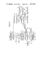
FIG. 4 is a flowchart showing an embodiment of the fuel supply control method according to the present invention; and
FIGS. 5 and 8 are diagrams showing data maps stored in the ROM;
FIG. 6 is a diagram showing relationship between the engine output power and the air/fuel ratio;
FIGS. 7, 9 and 10 are flowcharts respectively showing operations of the control circuit in other embodiments according to the present invention;
FIGS. 11 and 12 are diagram showing the constants PHAN and MeHAN.
DETAILED DESCRIPTION OF THE PREFERRED EMBODIMENT
Before entering into the explanation of the preferred embodiment of the invention, reference is first made to FIG. 1 in which the relation between the engine rpm and the absolute pressure PBA within the intake pipe is illustrated.
When the opening angle of the throttle valve is small and maintained almost constant, in such a period of idling operation, the relation between the engine rpm and the absolute pressure PBA becomes such as shown by the solid line of FIG. 1. In this state, a drop of the engine rpm immediately results in an increase of the absolute pressure PBA. With the increase of the absolute pressure PBA, the fuel injection time becomes long, which in turn causes an increase of the engine rpm Ne. On the other hand, when the engine rpm Ne increases, the absolute pressure immediately decreases to shorten the fuel injection time. Thus, the engine torque is reduced to slow down the engine rpm.
In this way, the engine rpm Ne is stabilized.
However, the above described process holds true only when the capacity of the intake pipe is small. If the capacity of the intake pipe is large, the absolute pressure PBA and the engine rpm Ne deviate from the solid line of FIG. 1. Specifically, if the engine rpm drops, the absolute pressure does not increase immediately. Therefore, the fuel injection time remains unchanged and the engine output torque does not increase enough to resume the engine rpm. Thus, the engine rpm Ne further decreases. Thereafter, the absolute pressure PBA increases after a time lag and, in turn, the engine output torque increases to raise the engine rpm Ne.
Similarly, the decrease of the absolute pressure PBA relative to the increase of the engine rpm Ne is delayed. With these reasons, the absolute pressure PBA fluctuates as illustrated by the dashed line of FIG. 1 repeatedly.
Thus, in the conventional arrangement where the basic fuel injection time is determined simply from the detected engine rpm and the absolute pressure within the intake manifold detected at a time point of the control operation, a problem of hunting of the engine rpm could not be avoided especially during the idling period of the engine.
FIG. 2 is a schematic illustration of an internal combustion engine which is provided with an electronic fuel supply control system operated in accordance with the controlling method according to the present invention. In FIG. 2, the engine designated at 4 is supplied with intake air taken at an air intake port 1 and which passes through an air cleaner 2 and an intake air passage 3. A throttle valve 5 is disposed in the intake air passage 3 so that the amount of the air taken into the engine is controlled by the opening degree of the throttle valve 5. The engine 4 has an exhaust gas passage 8 with a three-way catalytic converter 9 for promoting the reduction of noxious components such as CO, HC, and NOx in the exhaust gas of the engine.
Further, there is provided a throttle opening sensor 10, consisting of a potentiometer for example, which generates an output signal whose level correspondes to the opening degree of the throttle valve 5. Similarly, in the intake air passage 3 on the downstream side of the throttle valve 5, there is provided an absolute pressure sensor 11 which generates an output signal whose level correspondes to an absolute pressure within the intake air passage 3. The engine 4 is also provided with an engine coolant temperature sensor 12 which generates an output signal whose level corresponds to the temperature of the engine coolant, and a crank angle sensor 13 which generates pulse signals in accordance with the rotation of a crankshaft (not illustrated) of the engine. The crank angle sensor 13 is for example constructed so that a pulse signal is produced every 120° of revolution of the crankshaft. For supplying the fuel, an injector 15 is provided in the intake air passage 3 adjacent to each inlet valve (not shown) of the engine 4.
Output signals of the throttle opening sensor 10, the absolute pressure sensor 11, the engine coolant temperature sensor 12, the crank angle sensor 13 are connected to a control circuit 16 to which an input terminal of the fuel injector 15 is also connected.
Referring to FIG. 3, the construction of the control circuit 16 will be explained. The control circuit 16 includes a level adjustment circuit 21 for adjusting the level of the output signals of the throttle opening sensor 10, the absolute pressure sensor 11, the coolant temperature sensor 12. These output signals whose level is adjusted by the level adjusting circuit 21 are then applied to an input signal switching circuit 22 in which one of the input signals is selected and in turn outputted to an A/D (Analog to Digital) converter 23 which converts the input signal supplied in analog form to a digital signal. The output signal of the crank angle sensor 13 is applied to a waveform shaping circuit 24 which provides a TDC (Top Dead Center) signal according to the output signal of the crank angle sensor 13. A counter 25 is provided for measuring the time interval between each pulses of the TDC signal. The control circuit 16 further includes a drive circuit 26 for driving the injector 15, a CPU (Central Processing Unit) 27 for performing the arithmetic operation in accordance with programs stored in a ROM (Read Only Memory) 28 also provided in the control circuit 16, and a RAM 29. The input signal switching circuit 22, and the A/D converter 23, the counter 25, the drive circuit 26, the CPU 27, the ROM 28, and the RAM 29 are mutually connected by means of an input/output bus 30.
With this circuit construction, information of the throttle opening degree θth, absolute value of the intake air pressure PBA, and the engine coolant temperature TW are alternatively supplied to the CPU 27 via the input/output bus 30. From the counter 25, information of the count value Me indicative of an inverse number of the engine revolution Ne is supplied to the CPU 27 via the input/output bus 30. In the ROM 28, various operation programs for the CPU 27 and various data are stored previously.
In accordance with this operation programs, the CPU 27 reads the above mentioned various information and calculates the fuel injection time duration of the fuel injector 15 corresponding to the amount of fuel to be supplied to the engine 4, using a predetermined calculation formula in accordance with the information read by the CPU 27. During the thus calculated fuel injection time period, the drive circuit 26 actuates the injector 15 so that the fuel is supplied to the engine 4.
Each step of the operation of the method for controlling the supply of fuel according to the present invention, which is mainly performed by the control circuit 16, will be further explained with reference to the flowchart of FIG. 4.
In this sequencial operation, the absolute value of the intake air pressure PBA and the count value Me are read by the CPU 27 respectively as a sampled value PBAn and a sampled value Men, in synchronism with the occurence of every (nth) TDC signal (n being an integer). These sampled values PBAn and Men are in turn stored in the RAM 29 at a step 51. Subsequently, whether the engine 4 is operating under an idling state or not is detected at a step 52. Specifically, the idling state is detected in terms of the engine coolant temperature TW, the throttle opening degree θth, and the engine rpm Ne derived from the count value Me.
When the engine is not operating under the idling condition, which satisfys all of the conditions that the engine coolant temperature is high, the opening degree of the throttle valve is small, and the engine rpm is low, whether the engine rpm Ne is higher than a predetermined value Nz or not is detected at a step 53.
If Ne ≦Nz, whether or not the sampled value PBAn is greater than a predetermined value PBO (PBO being about atmospheric pressure value) is detected at a step 54. If PBAn ≦PBO, a sampled value PBAn-2, that is a before preceding sampled value (a value sampled at a sampling time 2 cycles before the latest sampling time), is read out from the RAM 29 at a step 55. Then a subtraction value ΔPBA between the latest sampled value PBAn and the sampled value PBAn-2 is calculated at a step 56. The sampled value PBAn of the absolute value of the intake air pressure PBA and the sampled values Men of the count value Me are stored in the RAM 29, for example, for the last six cycles of sampling. At a step 57, the subtraction value ΔPBA is compared with a predetermined reference value ΔPBAGH, corresponding to 64 mmHg for example. If ΔPBA ≦ΔPBAGH, a multiplication factor φ (for example, 4) is multiplied to the subtraction value ΔPBA and the sampled value PBAn is added to the product at a step 58. Thus, the corrected value PBA of the latest sampled value PBAn is calculated. If ΔPBA >ΔPBAGH, the subtraction value ΔPBA is made equal to the predetermined valu ΔPBAGH at a step 59 and the program goes to the step 58.
After that, whether or not the corrected value PBA is greater than a predetermined value PBO is detected at a step 60. If PBA ≦ΔPBO, the basic fuel injection time Ti is determined in accordance with the corrected value PBA, at a step 61, using a data map stored in ROM 28 previously. If PBA >PBO, then the corrected value PBA is made equal to PBO at a step 62 and the program goes to the step 61.
If Ne >Nz at the step 53 or if PBAn >PBO at the step 54, the latest sampled value PBAn is used as the corrected value PBA at the step 63 and afterwards, the program goes to the step 61.
On the other hand, at the step 52, if it is detected that the engine is operating under the idling condition, a sampled value Men-6 of the count value Me which is sampled at a sampling time six cycles before the sampling time of the latest sampled value Men is read out from the RAM 29 at a step 64. Then, a subtraction value ΔMe between the latest sampled value Men and the sampled value Men-6 is calculated at a step 65. After that, whether or not the subtraction value ΔMe is smaller than 0 is detected at a step 66. If ΔMe ≧0, it indicates that the engine rpm is dropping. Therefore, a correction coefficient βd corresponding to the latest sampled value Men is looked up, at a step 67, from the data map previously stored in the ROM 28 in such a manner as illustrated in FIG. 5.
By multiplying the thus obtained correction coefficient βd to the subtraction value ΔMe and adding a value 1 to the product, a correction coefficient α is calculated at a step 68. Then, whether or not this correction coefficient α is greater than an upper limit value αGH, is detected at a step 69. If α>αGH, then the correction coefficient α is made equal to the upper limit value αGH at a step 70. Conversely, if α≦αGH, the value of the correction coefficient α is maintained. A corrected value PBA of the latest sampled value PBAn is calculated at the step 71 and the basic fuel injection time Ti is calculated according to the thus corrected value of PBA at the step 61.
At the step 66, if ΔMe <0, it indicates that the engine rpm is going up and as in the step 67 mentioned above the correction coefficient βu corresponding to the latest sampled value Men is looked up from the data map previopusly stored in the ROM 28 as illustrated in FIG. 5 at a step 72. Subsequently, at a step 73, a correction coefficient α is calculated by multiplying the correction constant βu to the subtraction value ΔMe and adding a value of 1 to the product.
Then, whether or not this correction coefficient α is smaller than a lower limit value αGL (0.9 for example) is detected at a step 74. If α<αGL, the correction coefficient α is made equal to the lower limit value αGL at a step 75. If α≧αGL, the value of the correction coefficient α is maintained as it is. Then the calculation operation goes to the step 71 where the correction value PBA of the latest sampled value PBAn is derived.
In this embodiment of the fuel supply control method according to the present invention, the correction of the sampled value PBAn is performed according to two equations α=1+βΔMe, and PBA =α.PBAn. The amount of the correction of the sampled value PBAn is determined in proportional to the magnitude of the subtraction value ΔMe which corresponds to the variation of the engine rpm.
The correction constant β is looked up from a data map of Men -βd-βu shown in FIG. 5 since the subtraction value ΔMe with respect to the same width ΔNe of variation of the engine rpm becomes larger rapidly as the engine rpm becomes lower. Also, for improving the accuracy of the correction value PBA, one of the correction constants βd and βu is derived in accordance with the polarity of the subtraction value ΔMe. Specifically, when the engine rpm is reducing, the correction constant βd is looked up from the table and when the engine rpm is increasing, the correction constant βu which is set to be smaller than βd is looked up from the table. The correction coefficient α indicates the degree of the shift of the air/fuel ratio towards the rich side or the lean side, of the mixture to be supplied to the engine. Therefore, by providing the upper limit αGH and the lower limit αGL for the correction coefficient α, the correction coefficient α is controlled within the range where the engine output torgue can be controlled stably by controlling the air/fuel ratio as exemplary shown in FIG. 6. More particularly, if α>αGH, the air/fuel ratio becomes over rich so that it gets off from the range and does not control the engine output torque and if α<αGL, there is a fear of misfire.
The flowchart of FIG. 7 shows an operational sequence of another embodiment of the method for controlling the fuel supply according to the present invention.
In this sequence, since the steps up to the detection of ΔMe <0 at the step 66, are the same as the corresponding steps in the flowchart of FIG. 4, the same reference numerals are used and the explanation thereof is omitted.
If the result of the detection at the step 66 indicates that ΔMe ≧0 due to the drop of the engine rpm, the correction coefficient β0 and the upper limit value ΔMeGH of the subtraction value ΔMe corresponding to the latest sampled value Men respectively are looked up from the table stored previously in the ROM 28 as shown in FIG. 8 at a step 76. Then whether or not the subtraction value ΔMe is greater than the upper limit value ΔMeGH is detected at a step 77. If ΔMe >ΔMeGH, it indicates that the air/fuel ratio is over rich, then the subtraction value ΔMe is made equal to the upper limit value ΔMeGH at a step 78. Conversely, if ΔMe ≦ΔMeGH, the subtraction value ΔMe is maintained as it is. Subsequently, the correction value PBA of the latest sampled value PBAn is calculated in such manner that the correction constant β.sub. 0 is multiplied to the subtraction value ΔMe and the latest sampled value PBAn is added to the product at a step 79. On the other hand, if the result of the detection at the step 66 is ΔMe <0 due to the rise the engine rpm, then the correction constant β1 and the lower limit value ΔMeGL of the subtraction value ΔMe corresponding to the latest sampled value Men respectively are looked up, at a step 80, from data map which is previously stored in the ROM 28 in such a manner as illustrated in FIG. 8. Subsequently, whether or not the subtraction value ΔMe is smaller than the lower limit value ΔMeGL is detected at a step 81. If ΔMe <ΔMeGL, the subtraction value ΔMe is made equal to the lower limit value ΔMeGL at a step 82. This is because otherwise the air/fuel ratio becomes over lean and which in turn causes a misfire. Conversely if ΔMe ≧ΔMeGL, then the value of the subtraction value ΔMe is maintained as it is. Subsequently, the corrected value PBA of the latest sampled value PBAn is calculated at a step 83 in such a manner that the correction constant β1 is multiplied to the subtraction value ΔMe and the latest sampled value PBAn is added to the product.
In the thus operated method for controlling the fuel supply of an internal combustion engine, the latest sampled value is basically corrected according to the equation PBA =PBAn +βΔMe, and the amount of correction is determined in accordance with the subtration value ΔMe. For improving the accuracy of the correction, the correction constant β is determined in accordance with the polarity of the subtraction value ΔMe and the value of the latest sampled value Men. In addition, for limiting the correction constant β to the range where the engine output torque is controlled in accordance with the adjustment of the air/fuel ratio, the upper limit value ΔMeGH and the lower limit value ΔMeGL are determined in accordance with the polarity of the subtraction value ΔMe and the latest sampled value Men.
FIGS. 9 and 10 illustrate the other embodiment of the method for controlling the fuel suppy according to the present invention.
In the operational sequence of these embodiments, the correction is performed basically in accordance with the formula of PBA =PBAn +βΔMe used in the flowchart as shown in FIG. 7.
Therefore, the steps up to the step for determining the subtraction value ΔMe is the same as the steps in the previous embodiments.
However, since the subtraction value ΔMe becomes larger very quickly with respect to the same width ΔNe of variation of the engine rpm as the engine rpm becomes lower, the amount of the correction tends to be excessive. Therefore it is desirable to prevent the excessive increase of the corrected value by using an equation PBA =PBAn +βΔMe /Me. However, the calculation of such a formula as ΔMe /Me in a computer for example, requires a relatively long calculation time. Therefore, in these embodiments, constants PHAN or MeHAN (shown in FIG. 11 or 12 respectively) is established and an approximate value of 1/Me, |PHAN -PBAN | or |MeHAN -Men | is calculated in these embodiments. As shown in FIG. 9, after setting the subtraction value ΔMe at the step 77 or the step 78, the corrected value PBA of the latest sampled value PBAn is calculated at a step 79a according to an equation PBA =PBAn +β0 ΔMe |PHAN -PBAn |. In addition, after the subtraction value ΔMe is set at the step 81 or the step 82, the corrected value PBA is calculated according to an equation PBA =P.sub. BAn +β1 ΔMe |PHAN -PBAn | at a step 83a.
Similarly, in FIG. 10, after setting the subtraction value ΔMe at the step 77 or the step 78, the corrected value PBA is calculated according to an equation PBA =PBAn +β0 ΔMe |MeHan -Men | at a step 79b. In addition, after the subtraction value ΔMe is set at the step 81 or the step 82, the corrected value PBA is calculated according to an equation PBA =PBAn +β1 ΔMe |MeHAN -Men | at a step 83b.
Thus, according to the fuel supply control method of the present invention, the detected value of the pressure within the intake pipe is corrected according to the amount of the variation of the engine rpm. Therefore, the sampled value of the pressure within the intake pipe after the correction varies following the the variation of the engine rpm. Thus, a relationship between the engine rpm and the absolute pressure within the intake pipe which substantially locates on the curve shown by the solid line in FIG. 1 is obtained.
By determining the fuel supply amount according to the sampled value of the pressure within the intake pipe after the correction, the engine operation during such a period as the idling period is stabilized and the driveablilty of the engine is very much improved. This is because the phase delay of the restoring torque of the engine with respect to the change in the engine rpm is reduced even if the capacity of the intake pipe of the engine is relatively large.