US4598652A - Coal combustion to produce clean low-sulfur exhaust gas - Google Patents
Coal combustion to produce clean low-sulfur exhaust gas Download PDFInfo
- Publication number
- US4598652A US4598652A US06/772,524 US77252485A US4598652A US 4598652 A US4598652 A US 4598652A US 77252485 A US77252485 A US 77252485A US 4598652 A US4598652 A US 4598652A
- Authority
- US
- United States
- Prior art keywords
- sulfur
- coal
- oxysulfide
- combustion
- accordance
- Prior art date
- Legal status (The legal status is an assumption and is not a legal conclusion. Google has not performed a legal analysis and makes no representation as to the accuracy of the status listed.)
- Expired - Fee Related
Links
Images


Classifications
-
- F—MECHANICAL ENGINEERING; LIGHTING; HEATING; WEAPONS; BLASTING
- F23—COMBUSTION APPARATUS; COMBUSTION PROCESSES
- F23C—METHODS OR APPARATUS FOR COMBUSTION USING FLUID FUEL OR SOLID FUEL SUSPENDED IN A CARRIER GAS OR AIR
- F23C3/00—Combustion apparatus characterised by the shape of the combustion chamber
- F23C3/006—Combustion apparatus characterised by the shape of the combustion chamber the chamber being arranged for cyclonic combustion
- F23C3/008—Combustion apparatus characterised by the shape of the combustion chamber the chamber being arranged for cyclonic combustion for pulverulent fuel
-
- F—MECHANICAL ENGINEERING; LIGHTING; HEATING; WEAPONS; BLASTING
- F23—COMBUSTION APPARATUS; COMBUSTION PROCESSES
- F23D—BURNERS
- F23D1/00—Burners for combustion of pulverulent fuel
- F23D1/02—Vortex burners, e.g. for cyclone-type combustion apparatus
Definitions
- This invention is directed to a process for combusting sulfur-containing coal to produce a stack off-gas of greatly reduced sulfur dioxide content.
- coal-burning power plants are a major source of the pollutants, including SO 2 and NO x , which are responsible for damage to fish and plant life in the northeastern part of the country and in Canada due to the phenomenon now known as "acid rain.”
- the acid rain problem is complex, and the steps necessary to control the problem are not easy to accomplish.
- coal is the most abundant source of fossil fuel and will be available long after the earth's available petroleum supply is exhausted.
- most of the coal supplies in the Eastern and Midwestern United States are high in sulfur, and substitution of lower-sulfur Western coals, therefore, is not only expensive because of transportation cost but can cause further distress in the already economically deprived coal-mining areas.
- the cyclone furnace is a water-cooled, refractory-lined cylinder.
- Crushed or pulverized coal and primary air are fed at the burner end of the furnace and secondary air is fed into the the cylinder tangentially, thus creating a whirling or cyclonic motion to gases within the cylinder.
- Coal particles are entrained in the high velocity stream and thrown against the furnace wall by centrifugal force where they are held in the molten slag layer.
- the high-velocity tangential stream of secondary air supplies combustion oxygen to the coal particles.
- Molten slag drains to the bottom of the furnace from which it is removed.
- the cyclone furnace is thus a slagging type of coal burner.
- the invention is directed to a process in which liquid iron oxide containing materials are used under controlled conditions as a sulfur sink to remove combustion-product sulfur compounds from flue gases generated by combustion of sulfur-containing coal at high temperatures and high rates to provide a cleaned flue gas which may be released harmlessly to the atmosphere.
- Fine high-sulfur coal and a sulfur-fixing material from the group consisting of iron oxide, iron and copper oxide are combusted in a burner cavity such as that of a cyclone furnace using at least about 60% of the oxygen stoichiometrically required for completely combusting said coal to form a liquid oxysulfide phase and a turbulent atmosphere of combustion-product gases, with the liquid oxysulfide acting to scrub sulfur-containing gaseous species from the furnace atmosphere to yield an essentially sulfur-free flue gas and a liquid oxysulfide slag containing essentially all the sulfur contained in the feed coal.
- Temperature conditions are maintained between about 1100° C. and 1500° C.
- FIG. 1 illustrates a cyclone furnace usable in accordance with the invention
- FIG. 2 is a graph depicting the equilibrium sulfur content of flue gases in contact with a liquid iron oxysulfide of the formula FeS 0 .67 O x at various temperatures;
- FIG. 3 depicts the liquid phase area for liquid iron oxysulfide compositions in stable equilibrium with gas phases plotted as log (PH 2 S/PH 2 ) and log (PCO 2 /PCO) at 1100° C.;
- FIG. 4 is a plot constructed on the same basis as FIG. 3 but at 1200° C.;
- FIG. 5 is a plot constructed on the same basis as FIG. 3 but at 1300° C.;
- FIG. 6 is a sketch of an experimental furnace constructed to test the concepts of the invention.
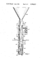
- FIG. 7 is a sketch of a coal burner used to fire the furnace of FIG. 6.
- reference character 10 depicts in partial section the steel shell of a horizontal cyclone furnace which is protected on the inner circumferential surface with steel tubes 11 adapted to carry cooling water.
- Refractory lining 12 which may, for example, comprise frozen slag derived from the ash content of coal combusted in the furnace overlies tubes 11 as a protection against abrasion and corrosion.
- Reference character 13 depicts an opening through which pulverulent coal and primary air may be fed into the furnace.
- Reentrant opening 14 enables exit of hot combustion-product gas while inhibiting escape of fly ash.
- Secondary air usually at substantial pressure and preferably preheated to circa 600° C. is admitted through tangentially-located opening 15.
- a sump 16 is provided for the collection of molten slag, which flows thence through tap hole 17 to the slag tank indicated at 18.
- coal from a bunker, not shown, which has been crushed and/or pulverized to -4 mesh and finer is weighed continuously in coal scales 19 and fed through coal feeder 20.
- Pulverulent sulfur-fixing material which may be an iron-containing material, e.g., taconite, mill scale or other iron oxide or iron powder may be introduced at one of several places. Conveniently, the iron oxide, in metered amounts, is mixed, and introduced into the furnace, with the coal. Copper oxide may also be used as a sulfur-fixing material.
- Primary air is introduced at 21, and the mixture of primary air and pulverulent coal is fed into the furnace at 13.
- the principal reactions occurring during the controlled combustion needed to produce desulfurization in accordance with the invention include the following:
- K w.g. is 1.646, while at 1100° C. it is 2.010, at 1200° C. it is 2.594, and at 1300° C. it is 3.119.
- This composition is kept stable in the combustion zone by control of the ratio of reducing constituents, primarily the CO 2 /CO ratio.
- FIG. 2 gives the calculated equilibrium sulfur contents of flue gases in contact with liquid Fe S o .67 O x at temperatures of 1100°, 1200° and 1300° C. based on a coal having an atomic ratio of hydrogen to carbon of 1:1, a sulfur content of 4% and a carbon content of 60%, by weight, i.e., a sulfur-to-carbon ratio of 0.067 in the coal and combustion in which 60 to 90 percent of stoichiometric air requirement is supplied.
- the sulfur to carbon ratio of the resulting gas ranges from 0.0035 to 1300° C. to 0.0032 at 1100° C. This indicates a removal from the gas of 95% or more of the sulfur originally contained in the coal.
- FIG. 2 also indicates that higher temperatures improve the thermodynamic efficiency. This factor is highly favorable since high temperatures rapidly increase kinetics and provide greater fluidity in the liquid phase.
- FIG. 2 also shows that as the oxygen level is increased, measured by percent stoichiometric air, the equilibrium level of sulfur in the gas phase also increases. Despite this factor a 91% removal of sulfur from the coal is still indicated at 1300° C., the case shown at 90% stoichiometric air. At this point the value of "x" in the formula Fe S o .67 O x approaches 1.3 and the sulfur to carbon ratio in the gas phase approaches 0.0057. At 1200° C. a range of gas compositions as measured by the ratio CO 2 /CO from 0.3/1 to greater than 10/1 are possible for stabilization of the oxysulfide liquid phase.
- FIGS. 3, 4 and 5 are plotted the area representing substantially the liquid phase area in equilibrium with the gas atmosphere.
- the Figures demonstrate that the significant gas phase species to be controlled for stabilizing the liquid phase are hydrogen sulfide, hydrogen, carbon dioxide and carbon monoxide.
- equilibrium “e” gas, iron, wustite, liquid
- equilibrium “h” wustite, magnetite, liquid
- equilibrium “h” wustite, magnetite, liquid
- equilibrium “h” does not exist at temperatures below 942° C.
- the point “h” in the Figures separates FeO (wustite) from Fe 3 O 4 (magnetite), and it is undesirable to attempt operation at CO 2 /CO ratios above point "h” as H 2 S then ceases to be a primary gas species. Instead, SO 2 becomes the sulfur-bearing gas species.
- the FeO/Fe 3 O 4 boundary gives the useful limit to PCO 2 /PCO values.
- the particle size of the coal is in a range between about one micron and about 100 microns and the iron oxide particle size is controlled in the range of about one micron to about 100 microns, e.g., minus 200 mesh.
- Iron oxide preferably is fed at rates of about 25% to about 100% excess of the stoichiometric quantity required to produce FeS based on the sulfur content of the feed coal.
- Thermodynamic efficiency of the desulfurization process is improved since wustite serves as a diluent or solvent for FeS and reduces the H 2 S pressure in equilibrium with the liquid, thereby contributing further to desulfurization of the gas.
- a Leahy coal of the composition below was selected for illustrative purposes:
- the Leahy coal was calculated to yield a flue gas containing 2620 ppm of SO 2 when completely combusted without added iron oxide. With iron oxide, the following results became predictable:
- combustion can be conducted at relatively high oXygen potentials (PCO 2 /PCO of ten to one) at high temperatures (T>1250° C.) and still achieve a high degree of desulfurization (PH 2 S ⁇ 200 ppm).
- PCO 2 /PCO ten to one
- PH 2 S ⁇ 200 ppm a high degree of desulfurization
- kinetics are more favorable, and also at high oxygen potentials there is a much better outlook for complete gasification of carbon to CO and CO 2 .
- the flue gas would contain about 260 ppm H 2 S.
- a furnace 30 having an internal cavity 31 essentially configured as an upright cylinder with a volume of about 128 liters as shown in FIG. 6 was constructed.
- Furnace 30 was made as a steel shell 32 lined with refractory brick 33.
- Throat 34 located on the vertical axis of cavity 31 was designed to contain a coal burner supported on flange 35 which delivered a turbulent burning mixture of fine coal, air and combustion gas to the interior of cavity 31.
- Exhaust 36 designed at the intake end 37 to avoid short circuiting of the combusting mixture and to conduct gaseous combustion product from the interior of the free space or cavity 31 to an afterburner (not shown) mounted about the outer end 38 was provided, in which carbon monoxide remaining in the furnace off-gas was completely combusted.
- FIG. 7 depicts in section the coal burner used in conjunction with the furnace of FIG. 6.
- the burner comprises a cylindrical body 40 designed to fit within throat 34 of furnace 30 and to be supported on flange 41.
- the burner has concentric inner and outer tubes 42 and 43 forming an air feed ring 44 therebetween.
- the tubes 42 and 43 are spaced apart and sealed at upper and lower ends by seals 44 and 45.
- Funnel 46 is provided at the top of tube 42 to facilitate feeding coal or a mixture of coal with iron and/or iron oxide powders.
- Air is fed at 47. Coal and air are mixed by the stationary mixer 48 provided with helical grooves 49 to which air is fed.
- Air fed through grooves 49 aspirates particulate coal or coal/iron/iron oxide mix through throat 50 and the mixture is forced through venturi throat 51 into the top of furnace 30.
- the bottom end of burner 40 comprising a radiation shield 52, is almost coincident with the inner top refractory face of furnace cavity 31.
- the helical placement of air grooves 49 imparts a turbulent swirling motion to the combusting mixture entering the free space of the furnace. Due to the small size of the furnace, no slag drain was provided.
- Test M coal was burned under conditions for complete combustion resulting in a measured stoichiometric stack gas SO 2 concentration of 4300 parts per million.
- Test N some residual added iron was present in the combustion chamber and a small amount of sulfur was removed.
- Tests A C and E about 27% if sulfur was rejected to iron in the coal ash.
- Tests F B and D iron was premixed with the coal as hematite having a particle size of about two microns and up to 53% of the sulfur was rejected.
- Test H magnetite having a particle size of about 30 microns was used with results similar to the hematite results.
- P Q and L magnetite and iron powders, mixed in the FeO proportion, provided stack gas SO 2 concentrations as low as 1400 parts per million, representing a sulfur removal of up to 70%. All results are reported in the following table:
- a cyclone furnace as illustrated in FIG. 1 of the drawing having a diameter of eight feet and a length of 11 feet is brought up to temperature of about 1300° C. by firing with natural gas and stoichiometric air. Slagging ingredients are introduced to form a slag coating on the furnace walls which coating becomes frozen in contact with the water cooled tubes lining the wall to form a protective layer. Firing is then commenced using a pulverized coal containing about 4% sulfur, about 40% volatiles, about 39% fixed carbon, about 9% ash and about 12% moisture. Particle size of the coal is about 20 microns. Coal is fed at a rate of 100,000 pounds per hour, mixed with about 15,000 pounds per hour of fine taconite having a particle size of about minus 20 mesh.
- Air preheated to about 600° C. at about 90% of the stoichiometric requirement for complete combustion of coal is fed at a rate of about ten million standard cubic feet per hour.
- Hot product gas having a sulfur dioxide content of about 1000 ppm and an average temperature of about 1100° C. is fed to an electric utility boiler to raise steam. Removal of about 80% of the sulfur content of the coal is achieved.
- Slag at a rate of about 26,000 pounds per hour (including pyritic iron from the coal) is led to the slag tank and is then granulated with water and pumped to disposal.
- the process of the invention provides a means for reducing the amount of sulfur dioxide released to the atmosphere from the combustion of sulfur-containing coal. Furthermore, since combustion is accomplished in the presence of a reduced oxygen partial pressure, the amounts of NO x are reduced as compared to conventional practice. It is of course desirable to accomplish combustion as rapidly as possible so as to secure reaction between molten iron oxysulfide droplets and sulfur species in the combustion atmosphere. Thus, fine coal, preheating of the air supply to about 600° C. e.g., about 200° to about 700° C. and possibly oxygen enrichment are all beneficial. Another advantage of the invention is that the removed sulfur is fixed in a dense inert solid thereby avoiding disposal problems.
Landscapes
- Engineering & Computer Science (AREA)
- Chemical & Material Sciences (AREA)
- Combustion & Propulsion (AREA)
- Mechanical Engineering (AREA)
- General Engineering & Computer Science (AREA)
Abstract
Description
CO+1/2O.sub.2 ⃡CO.sub.2 (1)
CO.sub.2 +H.sub.2 ⃡H.sub.2 O+CO (water-gas reaction) (2)
H.sub.2 +1/2S.sub.2 ⃡H.sub.2 S (3)
2CO⃡CO.sub.2 +C, (4)
______________________________________
Reaction (1) CO + 1/2O.sub.2 ⃡ CO.sub.2
Reaction (2) CO.sub.2 + H.sub.2 ⃡ H.sub.2 O + CO
Reaction (3) H.sub.2 + 1/2S.sub.2 ⃡ H.sub.2 S
 ##STR1##
 ##STR2##
 ##STR3##
T       F.° (1)
                 F.° (2)
                             F.° (3)
                                    t
K.°
        Calories Calories    Calories
                                    °C.
______________________________________
1273    -41,097  -1,370      -6,691 1000
1373    -39,038  -1,950      -5,506 1100
1473    -36,995  -2,629      -4,312 1200
1573    -34,959  -4,769      -3,136 1300
______________________________________
              TABLE 1
______________________________________
 t    Equi-   -RTlnPO.sub.2
                        -RTlnPS.sub.2
                                ##STR4##
                                        ##STR5##
°C.
     libria  k cal     k cal   (calc.) (calc.)
______________________________________
1000 e       86.0      40.5    -0.329  -2.328
1000 h       73.9      28.2    +0.710  -1.264
1100 e       83.1      40.6    -0.400  -2.356
1100 h       67.7      27.3    +0.834  -1.297
1200 e       80.0      41.4    -0.446  -2.431
1200 h       61.4      28.1    +0.934  -1.443
1300 e       77.0      44.0    -0.492  -2.622
1300 h       54.5      32.4     +1.0712
                                       -1.815
______________________________________
______________________________________
Leahy Coal:
 4.75% H.sub.2 O (percents below on moist basis)
67.19% C
 4.85% H
 1.52% N (neglected in calculations)
 2.77% S
Balance non-volatile constituents. Basis taken:
100 grams of coal.
let x = moles of CO in gas phase
let (5.60 - x) = moles CO.sub.2 in gas phase
let y = moles H.sub.2 in gas phase
let (2.69 - y) = moles H.sub.2 O in gas phase
 ##STR6##
 ##STR7##
______________________________________
              TABLE 2
______________________________________
Summary of Results - Leahy Coal
t °C.
            1000    1100       1200  1300
______________________________________
Equilibrium (e)
Gas, Iron
Wustite Liquid
Volume %
CO          15.9    16.7       17.2  17.7
CO.sub.2    7.5     6.6        6.2   5.7
H.sub.2     6.3     9.1        9.9   4.6
H.sub.2 O   4.9     2.1        1.4   6.7
H.sub.2 S (ppm)
            300     402        365   109
(Bal N.sub.2)
Equilibrium (h)
Gas, Wustite
Magntite,
Liquid Volume %
CO          2.9     2.3        1.8   1.1
CO.sub.2    14.6    15.2       15.4  12.3
H.sub.2     0.9     0.6        0.4   0.1
H.sub.2 O   7.5     7.8        7.9   6.3
H.sub.2 S (ppm)
            475     289        135   18
(Bal N.sub.2)
______________________________________
__________________________________________________________________________
           Rate                   SO.sub.2  Ratio of
           Coal,                  Assay,    Process
                                                 Estimated
        Mass
           g/min        Process
                             Total
                                  ppm Sulfur
                                            Air to
                                                 Air
        Fed,
           (Coal
               % CO     Air, g
                             Air, g
                                  (Dry
                                      Removed,
                                            Total
                                                 In-Leakage
Test
   Feed g  Only)
               (Cavity)
                    T, °C.
                        mol/min
                             mol/min
                                  Basis)
                                      %     Air  %
__________________________________________________________________________
Base
   Coal -- 35  0    --  11.9.sup.1
                             11.9.sup.1
                                  .sup. 4,700.sup.1
                                       0    1.00  0
M  Coal 1,300
           56.5
               0    1,315
                        19.2 19.2 4,300
                                       8    1.00  0
N  Coal 1,200
           50  0    1,340
                        14.0 14.0 4,100
                                      13    1.00 21
A  Coal 1,200
           46  7    1,250
                        9.4  14.0 3,550
                                      25    0.67 11
C  Coal 1,400
           50  7    1,230
                        9.4  14.0 3,400
                                      28    0.67 21
E  Coal    40  7    1,250
                        8.3  11.8 3,250
                                      31    0.70 15
F  80%  1,400
           37  7    1,240
                        5.8  11.0 2,700
                                      43    0.53 15
   Coal        (%
   20%         CO.sub.2 =
   Fe.sub.2 O.sub.3
               10.1)
B  Same 1,400
           35  7    1,230
                        6.5  12.5 2,200
                                      53    0.52 -5
   as F
D  Same 1,400
           59  7    1,220
                        9.4  14.0 3,600
                                      23    0.67 44
   as F
O  80%  1,250
           40  3    1,250
                        9.8  13.1 3,150
                                      33    0.75  4
   Coal
   20%
   Fe.sub.3 O.sub.4
H  Same 1,400
           45  7    1,250
                        8.7  12.8 2,508
                                      47    0.68 20
   as O
P  80%  3,500
           31  7    1,250
                        5.2  9.8  1,400
                                      70    0.53  7
   Coal
   16.9%
   Fe.sub.3 O.sub.4
   3.1% Fe
Q  Same 3,400
           34  7    1,320
                        6.3  10.5 1,700
                                      64    0.60 10
   as P
L  Same 1,350
           49  7    1,240
                        8.3  15.1 1,700
                                      64    0.55 11
   as P
__________________________________________________________________________
 Note: .sup.1 Base Case.
Claims (16)
Priority Applications (1)
| Application Number | Priority Date | Filing Date | Title |
|---|---|---|---|
| US06/772,524 US4598652A (en) | 1985-09-04 | 1985-09-04 | Coal combustion to produce clean low-sulfur exhaust gas |
Applications Claiming Priority (1)
| Application Number | Priority Date | Filing Date | Title |
|---|---|---|---|
| US06/772,524 US4598652A (en) | 1985-09-04 | 1985-09-04 | Coal combustion to produce clean low-sulfur exhaust gas |
Publications (1)
| Publication Number | Publication Date |
|---|---|
| US4598652A true US4598652A (en) | 1986-07-08 |
Family
ID=25095361
Family Applications (1)
| Application Number | Title | Priority Date | Filing Date |
|---|---|---|---|
| US06/772,524 Expired - Fee Related US4598652A (en) | 1985-09-04 | 1985-09-04 | Coal combustion to produce clean low-sulfur exhaust gas |
Country Status (1)
| Country | Link |
|---|---|
| US (1) | US4598652A (en) |
Cited By (18)
| Publication number | Priority date | Publication date | Assignee | Title |
|---|---|---|---|---|
| US4808386A (en) * | 1987-03-02 | 1989-02-28 | Texaco Inc. | Partial oxidation of sulfur-containing solid carbonaceous fuel |
| US4889699A (en) * | 1987-05-19 | 1989-12-26 | Texaco Inc. | Partial oxidation process |
| US4952380A (en) * | 1985-06-27 | 1990-08-28 | Texaco Inc. | Partial oxidation process |
| US5078752A (en) * | 1990-03-12 | 1992-01-07 | Northern States Power Company | Coal gas productions coal-based combined cycle power production |
| WO1992003211A1 (en) * | 1990-08-17 | 1992-03-05 | Fritz Schoppe | Process and device for complete, dry desulphuration of combustion waste gases containing so2 and dust |
| US5720785A (en) * | 1993-04-30 | 1998-02-24 | Shell Oil Company | Method of reducing hydrogen cyanide and ammonia in synthesis gas |
| US20020184817A1 (en) * | 2000-06-26 | 2002-12-12 | Ada Environmental Solutions, Llc | Low sulfur coal additive for improved furnace operation |
| US6612249B2 (en) | 2000-03-24 | 2003-09-02 | Unique Patents.Com, Llc | Zero NOx gaseous passivation process |
| US20040040438A1 (en) * | 2002-08-30 | 2004-03-04 | Baldrey Kenneth E. | Oxidizing additives for control of particulate emissions |
| US20050039653A1 (en) * | 2003-08-21 | 2005-02-24 | D'agostini Mark Daniel | Oxygen-enriched co-firing of secondary fuels in slagging cyclone combustors |
| US20050039654A1 (en) * | 2003-08-21 | 2005-02-24 | D'agostini Mark Daniel | Selective oxygen enrichment in slagging cyclone combustors |
| US20110030592A1 (en) * | 2000-06-26 | 2011-02-10 | Ada Environmental Solutions, Llc | Additives for mercury oxidation in coal-fired power plants |
| US8124036B1 (en) | 2005-10-27 | 2012-02-28 | ADA-ES, Inc. | Additives for mercury oxidation in coal-fired power plants |
| US8383071B2 (en) | 2010-03-10 | 2013-02-26 | Ada Environmental Solutions, Llc | Process for dilute phase injection of dry alkaline materials |
| US8784757B2 (en) | 2010-03-10 | 2014-07-22 | ADA-ES, Inc. | Air treatment process for dilute phase injection of dry alkaline materials |
| US8974756B2 (en) | 2012-07-25 | 2015-03-10 | ADA-ES, Inc. | Process to enhance mixing of dry sorbents and flue gas for air pollution control |
| US9017452B2 (en) | 2011-11-14 | 2015-04-28 | ADA-ES, Inc. | System and method for dense phase sorbent injection |
| US10350545B2 (en) | 2014-11-25 | 2019-07-16 | ADA-ES, Inc. | Low pressure drop static mixing system |
Citations (3)
| Publication number | Priority date | Publication date | Assignee | Title |
|---|---|---|---|---|
| US4173454A (en) * | 1977-07-18 | 1979-11-06 | Heins Sidney M | Method for removal of sulfur from coal in stoker furnaces |
| US4377118A (en) * | 1981-12-21 | 1983-03-22 | Nalco Chemical Company | Process for reducing slag build-up |
| US4388877A (en) * | 1981-07-07 | 1983-06-21 | Benmol Corporation | Method and composition for combustion of fossil fuels in fluidized bed |
-
1985
- 1985-09-04 US US06/772,524 patent/US4598652A/en not_active Expired - Fee Related
Patent Citations (3)
| Publication number | Priority date | Publication date | Assignee | Title |
|---|---|---|---|---|
| US4173454A (en) * | 1977-07-18 | 1979-11-06 | Heins Sidney M | Method for removal of sulfur from coal in stoker furnaces |
| US4388877A (en) * | 1981-07-07 | 1983-06-21 | Benmol Corporation | Method and composition for combustion of fossil fuels in fluidized bed |
| US4377118A (en) * | 1981-12-21 | 1983-03-22 | Nalco Chemical Company | Process for reducing slag build-up |
Cited By (32)
| Publication number | Priority date | Publication date | Assignee | Title |
|---|---|---|---|---|
| US4952380A (en) * | 1985-06-27 | 1990-08-28 | Texaco Inc. | Partial oxidation process |
| US4808386A (en) * | 1987-03-02 | 1989-02-28 | Texaco Inc. | Partial oxidation of sulfur-containing solid carbonaceous fuel |
| US4889699A (en) * | 1987-05-19 | 1989-12-26 | Texaco Inc. | Partial oxidation process |
| US5078752A (en) * | 1990-03-12 | 1992-01-07 | Northern States Power Company | Coal gas productions coal-based combined cycle power production |
| WO1992003211A1 (en) * | 1990-08-17 | 1992-03-05 | Fritz Schoppe | Process and device for complete, dry desulphuration of combustion waste gases containing so2 and dust |
| US5720785A (en) * | 1993-04-30 | 1998-02-24 | Shell Oil Company | Method of reducing hydrogen cyanide and ammonia in synthesis gas |
| US6612249B2 (en) | 2000-03-24 | 2003-09-02 | Unique Patents.Com, Llc | Zero NOx gaseous passivation process |
| US8919266B2 (en) | 2000-06-26 | 2014-12-30 | ADA-ES, Inc. | Low sulfur coal additive for improved furnace operation |
| US7332002B2 (en) | 2000-06-26 | 2008-02-19 | Ada Environmental Solutions, Llc | Low sulfur coal additive for improved furnace operation |
| US8439989B2 (en) | 2000-06-26 | 2013-05-14 | ADA-ES, Inc. | Additives for mercury oxidation in coal-fired power plants |
| US6729248B2 (en) | 2000-06-26 | 2004-05-04 | Ada Environmental Solutions, Llc | Low sulfur coal additive for improved furnace operation |
| US6773471B2 (en) | 2000-06-26 | 2004-08-10 | Ada Environmental Solutions, Llc | Low sulfur coal additive for improved furnace operation |
| US9951287B2 (en) | 2000-06-26 | 2018-04-24 | ADA-ES, Inc. | Low sulfur coal additive for improved furnace operation |
| US20040016377A1 (en) * | 2000-06-26 | 2004-01-29 | Oil Sands Underground Mining, Inc. | Low sulfur coal additive for improved furnace operation |
| US11168274B2 (en) | 2000-06-26 | 2021-11-09 | ADA-ES, Inc. | Low sulfur coal additive for improved furnace operation |
| US20110030592A1 (en) * | 2000-06-26 | 2011-02-10 | Ada Environmental Solutions, Llc | Additives for mercury oxidation in coal-fired power plants |
| US20020184817A1 (en) * | 2000-06-26 | 2002-12-12 | Ada Environmental Solutions, Llc | Low sulfur coal additive for improved furnace operation |
| US6797035B2 (en) | 2002-08-30 | 2004-09-28 | Ada Environmental Solutions, Llc | Oxidizing additives for control of particulate emissions |
| US20040040438A1 (en) * | 2002-08-30 | 2004-03-04 | Baldrey Kenneth E. | Oxidizing additives for control of particulate emissions |
| US6968791B2 (en) | 2003-08-21 | 2005-11-29 | Air Products And Chemicals, Inc. | Oxygen-enriched co-firing of secondary fuels in slagging cyclone combustors |
| US6910432B2 (en) | 2003-08-21 | 2005-06-28 | Air Products And Chemicals, Inc. | Selective oxygen enrichment in slagging cyclone combustors |
| US20050039654A1 (en) * | 2003-08-21 | 2005-02-24 | D'agostini Mark Daniel | Selective oxygen enrichment in slagging cyclone combustors |
| US20050039653A1 (en) * | 2003-08-21 | 2005-02-24 | D'agostini Mark Daniel | Oxygen-enriched co-firing of secondary fuels in slagging cyclone combustors |
| US8293196B1 (en) | 2005-10-27 | 2012-10-23 | ADA-ES, Inc. | Additives for mercury oxidation in coal-fired power plants |
| US8124036B1 (en) | 2005-10-27 | 2012-02-28 | ADA-ES, Inc. | Additives for mercury oxidation in coal-fired power plants |
| US8784757B2 (en) | 2010-03-10 | 2014-07-22 | ADA-ES, Inc. | Air treatment process for dilute phase injection of dry alkaline materials |
| US9149759B2 (en) | 2010-03-10 | 2015-10-06 | ADA-ES, Inc. | Air treatment process for dilute phase injection of dry alkaline materials |
| US8383071B2 (en) | 2010-03-10 | 2013-02-26 | Ada Environmental Solutions, Llc | Process for dilute phase injection of dry alkaline materials |
| US9017452B2 (en) | 2011-11-14 | 2015-04-28 | ADA-ES, Inc. | System and method for dense phase sorbent injection |
| US8974756B2 (en) | 2012-07-25 | 2015-03-10 | ADA-ES, Inc. | Process to enhance mixing of dry sorbents and flue gas for air pollution control |
| US10350545B2 (en) | 2014-11-25 | 2019-07-16 | ADA-ES, Inc. | Low pressure drop static mixing system |
| US11369921B2 (en) | 2014-11-25 | 2022-06-28 | ADA-ES, Inc. | Low pressure drop static mixing system |
Similar Documents
| Publication | Publication Date | Title |
|---|---|---|
| US4572085A (en) | Coal combustion to produce clean low-sulfur exhaust gas | |
| US4598652A (en) | Coal combustion to produce clean low-sulfur exhaust gas | |
| US4599955A (en) | Coal slagging burner for producing clean low-sulfur fuel gas | |
| CN1080313C (en) | Hot oxygen blast furnace injection system | |
| JP2967394B2 (en) | Desulfurization of carbonaceous fuel | |
| US4345990A (en) | Method for recovering oil and/or gas from carbonaceous materials | |
| JPS60500674A (en) | Methods for desulfurizing, denitrifying and oxidizing carbonaceous fuels | |
| US20150152344A1 (en) | Melt gasifier system | |
| US4095960A (en) | Apparatus and method for the gasification of solid carbonaceous material | |
| CN1004879B (en) | Process for the smelting reduction of ores | |
| EP1114190B1 (en) | Blast furnace with narrowed top section and method of using | |
| US3607224A (en) | Direct reduction of iron ore | |
| US5364421A (en) | Coal blends having improved ash viscosity | |
| NO822797L (en) | METHOD AND APPARATUS FOR MANUFACTURING SYNTHESIC GAS | |
| TW304982B (en) | ||
| US3110578A (en) | Gasification process for the production of synthesis gases | |
| US4181704A (en) | Process for the removal of sulfurous gases from the emissions of chemical processes | |
| US4851151A (en) | Process for production of synthesis gas with reduced sulfur content | |
| JPH07216464A (en) | Weltz reprocessing of material containing zinc, lead and iron oxide | |
| JPH0436386A (en) | Improvement of slag | |
| US4427529A (en) | Distilling shale oil from oil shale | |
| US4604268A (en) | Methods of desulfurizing gases | |
| JPH0332612B2 (en) | ||
| EP0301714A2 (en) | Sulfur removal by sorbent injection in secondary combustion zones | |
| Reiter et al. | The RecoDust process—upscale of a pilot plant |
Legal Events
| Date | Code | Title | Description |
|---|---|---|---|
| AS | Assignment |
Owner name: AMAX INC., AMAX CENTER, GREENWICH, CONNECTICUT, 0 Free format text: ASSIGNMENT OF ASSIGNORS INTEREST.;ASSIGNOR:HEPWORTH, MALCOLM T.;REEL/FRAME:004453/0101 Effective date: 19850827 |
|
| FEPP | Fee payment procedure |
Free format text: PAYOR NUMBER ASSIGNED (ORIGINAL EVENT CODE: ASPN); ENTITY STATUS OF PATENT OWNER: LARGE ENTITY |
|
| FPAY | Fee payment |
Year of fee payment: 4 |
|
| FPAY | Fee payment |
Year of fee payment: 8 |
|
| SULP | Surcharge for late payment | ||
| REMI | Maintenance fee reminder mailed | ||
| LAPS | Lapse for failure to pay maintenance fees | ||
| FP | Lapsed due to failure to pay maintenance fee |
Effective date: 19980708 |
|
| AS | Assignment |
Owner name: CYPRUS AMAX COAL COMPANY, COLORADO Free format text: ASSIGNMENT OF ASSIGNORS INTEREST;ASSIGNOR:CYPRUS AMAX MINERALS COMPANY;REEL/FRAME:009942/0724 Effective date: 19990427 |
|
| AS | Assignment |
Owner name: RAG AMERICAN COAL COMPANY, COLORADO Free format text: MERGER;ASSIGNOR:CYPRUS AMAX COAL COMPANY;REEL/FRAME:010188/0696 Effective date: 19990630 |
|
| AS | Assignment |
Owner name: CITICORP NORTH AMERICA, INC., DELAWARE Free format text: ASSIGNMENT OF ASSIGNORS INTEREST;ASSIGNORS:FOUNDATION AMERICAN COAL COMPANY, LLC;FOUNDATION COAL DEVELOPMENT CORPORATON;FOUNDATION COAL WEST, INC.;REEL/FRAME:015642/0450 Effective date: 20040730 |
|
| AS | Assignment |
Owner name: FOUNDATION AMERICAN COAL COMPANY, LLC, MARYLAND Free format text: CHANGE OF NAME;ASSIGNOR:RAG AMERICAN COAL COMPANY, LLC;REEL/FRAME:015819/0382 Effective date: 20040714 Owner name: RAG AMERICAN COAL COMPANY, LLC, MARYLAND Free format text: CERTIFICATE OF CONVERSION;ASSIGNOR:RAG AMERICAN COAL COMPANY;REEL/FRAME:015819/0535 Effective date: 20040310 |
|
| STCH | Information on status: patent discontinuation |
Free format text: PATENT EXPIRED DUE TO NONPAYMENT OF MAINTENANCE FEES UNDER 37 CFR 1.362 |
|
| AS | Assignment |
Owner name: ALPHA COAL WEST, LLC (SUCCESSOR BY CONVERSION TO A Free format text: RELEASE BY SECURED PARTY;ASSIGNOR:CITICORP NORTH AMERICA, INC.;REEL/FRAME:050147/0137 Effective date: 20190821 Owner name: ALPHA AMERICAN COAL COMPANY, LLC (F/K/A FOUNDATION Free format text: RELEASE BY SECURED PARTY;ASSIGNOR:CITICORP NORTH AMERICA, INC.;REEL/FRAME:050147/0137 Effective date: 20190821 Owner name: DFDSTE, LLC (AS SUCCESSOR BY CONVERSION TO DFDSTE Free format text: RELEASE BY SECURED PARTY;ASSIGNOR:CITICORP NORTH AMERICA, INC.;REEL/FRAME:050147/0137 Effective date: 20190821 |