US4595892A - Coaxial cavity resonator having a dielectric insert which impedance matches active device useable with resonator - Google Patents
Coaxial cavity resonator having a dielectric insert which impedance matches active device useable with resonator Download PDFInfo
- Publication number
- US4595892A US4595892A US06/598,733 US59873384A US4595892A US 4595892 A US4595892 A US 4595892A US 59873384 A US59873384 A US 59873384A US 4595892 A US4595892 A US 4595892A
- Authority
- US
- United States
- Prior art keywords
- resonator
- active device
- coaxial
- diode
- center
- Prior art date
- Legal status (The legal status is an assumption and is not a legal conclusion. Google has not performed a legal analysis and makes no representation as to the accuracy of the status listed.)
- Expired - Fee Related
Links
Images
Classifications
-
- H—ELECTRICITY
- H03—ELECTRONIC CIRCUITRY
- H03B—GENERATION OF OSCILLATIONS, DIRECTLY OR BY FREQUENCY-CHANGING, BY CIRCUITS EMPLOYING ACTIVE ELEMENTS WHICH OPERATE IN A NON-SWITCHING MANNER; GENERATION OF NOISE BY SUCH CIRCUITS
- H03B19/00—Generation of oscillations by non-regenerative frequency multiplication or division of a signal from a separate source
- H03B19/16—Generation of oscillations by non-regenerative frequency multiplication or division of a signal from a separate source using uncontrolled rectifying devices, e.g. rectifying diodes or Schottky diodes
- H03B19/18—Generation of oscillations by non-regenerative frequency multiplication or division of a signal from a separate source using uncontrolled rectifying devices, e.g. rectifying diodes or Schottky diodes and elements comprising distributed inductance and capacitance
Definitions
- This invention relates to coaxial cavities and more particularly to a tunable fixed length coaxial cavity resonator.
- Coaxial type resonators with a diode or other active device are well known in the state of the art.
- Such resonators include an outer conductor and a center conductor coaxial with the outer conductor with one end of the resonator connected to an active device and the opposite end terminated in a short.
- the tuning of the diode or active device is accomplished by a sliding short at the end opposite the active device that slides between the inner and outer conductor and tunes the length of the cavity.
- this type of tunable short may be difficult to access or the space requirements may not allow for such a variable length cavity.
- the coaxial tuner in series with and for tuning an active device while heat sinking the device, comprises a fixed length of coaxial line having a center conductor and an outer conductor with the center conductor coupled at one end in series with the active device and terminated at the opposite end in a heat sinking short across the center conductor and outer conductor.
- the fixed length of the coaxial line is selected to resonate at about the desired input frequency.
- a preformed solid ring of dielectric material having an outer diameter and inner diameter sized to fit between the center conductor and outer conductor is disposed in the cavity adjacent the termination. The length of the ring and the dielectric constant of the material is selected to match the impedance characteristics of the active device at the input frequency.
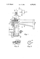
- FIG. 1 is a side elevation view of a multiplier including a cavity resonator according to one embodiment of the present invention with parts of the multiplier removed to illustrate the diode and the tuning element;
- FIG. 2 illustrates in more detail the mounting of the diode to the waveguide in FIG. 1;
- FIG. 3 is an end view of the tuning dielectric ring in accordance with one embodiment of the present invention.
- the coaxial cavity resonator comprises a grounded outer conductor 11 and a coaxial inner conductor 13.
- the inner conductor 13 is coupled at one end to a step recovery diode 15 and at the opposite to the outer conductor via a covering conductive shorting plate 16.
- the plate 16 covers the entire end of the resonator.
- the cathode C of the diode 15 is coupled to the center conductor 13 and the anode is coupled via a center conductor 31 of a coaxial line 30 to terminal 21.
- An input frequency of 3 GHz (gigahertz), for example, is applied at terminal 21 of line 30.
- the line 30 with its outer conductor and dielectric spacer 31a has a characteristic impedance of, for example, 35 ohms to transfer the 50 ohm impedance at terminal to the 24 ohm diode impedance.
- the diode 15 is located and centralized in the middle of the width of a reduced height rectangular waveguide section 25 for exciting in the waveguide 25 a signal at a third harmonic (12 GHz) of the input frequency.
- the anode A of the diode is connected to the center conductor 31 of line 30 which extends in spaced manner through aperture 35 in the top wall 37 of reduced height rectangular waveguide section 25.
- the center conductor 31 includes a circular flange 33 and is spaced from the wall 37 by a ring-shaped dielectric body 39.
- the flange 33, waveguide top wall 37 and dielectric body 39 form a bypass capacitor which acts as an open for the incoming 4 GHz input frequency signals and as a short for the 12 GHz harmonic output frequency signals. This isolates terminal 21 from the x3 multiple output signals at 12 GHz.
- the dc bias for the diode 15 is provided by the diode rectified current across resistor 41.
- the DC bias circuit is shown schematically in FIG.
- Resistor 41 and RF choke 42 are coupled in series to the center conductor 31 of input transmission line 30 which is coupled to ground via plate 16.
- Capacitor 43 is a bypass capacitor. The RF is isolated from the bias circuit by the RF choke 42 and bypass capacitor 43.
- the coaxial cavity from the connection to the cathode at point C to the end of the cavity at plate 16 is of a fixed length L that is one-quarter wavelength resonant at the input frequency of 4 GHz.
- L 1.087 inohes.
- the diode 15 is heat sunk by its connect from the center conductor 13 to the ground short at plate 16.
- a dielectric ring 17 as illustrated in end view in FIG. 3 is adapted to fit between the center conductor 13 and outer conductor 11 and is placed adjacent the shorting plate 16 to provide tuning adjustment so as to match the impedance characteristic of the diode 15 at the input frequency to maximize coupling to the diode.
- the impedance can be changed from a capacitive reactance to an inductive reactance impedance value or from -j49.492 ohms to +j30.198 ohms.
- the distances in the table are relative to the total length of the cavity.
- the dielectric material was Teflon with a dielectric constant of about 2.2.
- the ring 17 has a flange portion (illustrated as 17a) at one end adapted to fit in an annular groove 11a in the outer conductor at the shorting plate 16 end so as to lock the ring 17 at the shorting end as shown.
- the third harmonic frequency is maximized by the reactive tuning provided by the covering end short 50 across one end of the reduced height waveguide 25.
- This short is located between 1/4 and 1/2 wavelength from the diode at the desired harmonic frequency of 12 GHz.
- the length of this short from the diode is adjusted by changing the length of waveguide section 51 to achieve the appropriate reactance in parallel with the diode.
- the opposite end of the reduced height waveguide 25 is coupled to a full height waveguide 60 by a linear tapered waveguide section 55.
Landscapes
- Waveguide Connection Structure (AREA)
Abstract
Description
              TABLE 1
______________________________________
DIST           REAL    IMAG
______________________________________
 0             0       -49.492
.1             0       -46.013
.2             0       -38.022
.3             0       -84.79
.4             0       -8.2361
.5             0       7.5846
.6             0       19.259
.7             0       25.937
.8             0       28.768
.9             0       29.575
 1             0       30.198
______________________________________
Claims (4)
Priority Applications (1)
| Application Number | Priority Date | Filing Date | Title |
|---|---|---|---|
| US06/598,733 US4595892A (en) | 1984-04-10 | 1984-04-10 | Coaxial cavity resonator having a dielectric insert which impedance matches active device useable with resonator |
Applications Claiming Priority (1)
| Application Number | Priority Date | Filing Date | Title |
|---|---|---|---|
| US06/598,733 US4595892A (en) | 1984-04-10 | 1984-04-10 | Coaxial cavity resonator having a dielectric insert which impedance matches active device useable with resonator |
Publications (1)
| Publication Number | Publication Date |
|---|---|
| US4595892A true US4595892A (en) | 1986-06-17 |
Family
ID=24396702
Family Applications (1)
| Application Number | Title | Priority Date | Filing Date |
|---|---|---|---|
| US06/598,733 Expired - Fee Related US4595892A (en) | 1984-04-10 | 1984-04-10 | Coaxial cavity resonator having a dielectric insert which impedance matches active device useable with resonator |
Country Status (1)
| Country | Link |
|---|---|
| US (1) | US4595892A (en) |
Cited By (6)
| Publication number | Priority date | Publication date | Assignee | Title |
|---|---|---|---|---|
| US5422613A (en) * | 1992-07-15 | 1995-06-06 | State Of Israel, Ministry Of Defense Armament Development Authority, Rafael | Varactor diode frequency multiplier |
| US5731752A (en) * | 1996-04-17 | 1998-03-24 | Loral Vought Systems Corporation | Microwave signal frequency multiplier |
| US6265934B1 (en) | 1999-12-16 | 2001-07-24 | Lockheed Martin Corporation | Q-switched parametric cavity amplifier |
| US6281746B1 (en) | 1999-12-16 | 2001-08-28 | Lockheed Martin Corporation | Parametric cavity microwave amplifier |
| US6297716B1 (en) | 1999-12-16 | 2001-10-02 | Lockheed Martin Corporation | Q-switched cavity multiplier |
| US11365760B1 (en) | 2017-07-04 | 2022-06-21 | Damian Daigle | Fire rated isolation washer |
Citations (7)
| Publication number | Priority date | Publication date | Assignee | Title |
|---|---|---|---|---|
| US3353087A (en) * | 1965-02-15 | 1967-11-14 | Gen Telephone & Elect | Shunt-type coaxial to waveguide harmonic generator |
| US3525057A (en) * | 1967-03-30 | 1970-08-18 | Univ Iowa State Res Found Inc | Impedance-matching device |
| US3691479A (en) * | 1970-08-24 | 1972-09-12 | Bruce G Malcolm | Multi-diode single cavity microwave oscillators |
| US3872412A (en) * | 1974-04-26 | 1975-03-18 | Bell Telephone Labor Inc | Dielectric-loaded chokes |
| US4059815A (en) * | 1975-07-31 | 1977-11-22 | Matsushita Electric Industrial Co., Limited | Coaxial cavity resonator |
| JPS5438744A (en) * | 1977-09-01 | 1979-03-23 | Nec Corp | Waveguide circuit |
| US4389624A (en) * | 1980-04-04 | 1983-06-21 | Matsushita Electric Industrial Company, Limited | Dielectric-loaded coaxial resonator with a metal plate for wide frequency adjustments |
-
1984
- 1984-04-10 US US06/598,733 patent/US4595892A/en not_active Expired - Fee Related
Patent Citations (7)
| Publication number | Priority date | Publication date | Assignee | Title |
|---|---|---|---|---|
| US3353087A (en) * | 1965-02-15 | 1967-11-14 | Gen Telephone & Elect | Shunt-type coaxial to waveguide harmonic generator |
| US3525057A (en) * | 1967-03-30 | 1970-08-18 | Univ Iowa State Res Found Inc | Impedance-matching device |
| US3691479A (en) * | 1970-08-24 | 1972-09-12 | Bruce G Malcolm | Multi-diode single cavity microwave oscillators |
| US3872412A (en) * | 1974-04-26 | 1975-03-18 | Bell Telephone Labor Inc | Dielectric-loaded chokes |
| US4059815A (en) * | 1975-07-31 | 1977-11-22 | Matsushita Electric Industrial Co., Limited | Coaxial cavity resonator |
| JPS5438744A (en) * | 1977-09-01 | 1979-03-23 | Nec Corp | Waveguide circuit |
| US4389624A (en) * | 1980-04-04 | 1983-06-21 | Matsushita Electric Industrial Company, Limited | Dielectric-loaded coaxial resonator with a metal plate for wide frequency adjustments |
Cited By (6)
| Publication number | Priority date | Publication date | Assignee | Title |
|---|---|---|---|---|
| US5422613A (en) * | 1992-07-15 | 1995-06-06 | State Of Israel, Ministry Of Defense Armament Development Authority, Rafael | Varactor diode frequency multiplier |
| US5731752A (en) * | 1996-04-17 | 1998-03-24 | Loral Vought Systems Corporation | Microwave signal frequency multiplier |
| US6265934B1 (en) | 1999-12-16 | 2001-07-24 | Lockheed Martin Corporation | Q-switched parametric cavity amplifier |
| US6281746B1 (en) | 1999-12-16 | 2001-08-28 | Lockheed Martin Corporation | Parametric cavity microwave amplifier |
| US6297716B1 (en) | 1999-12-16 | 2001-10-02 | Lockheed Martin Corporation | Q-switched cavity multiplier |
| US11365760B1 (en) | 2017-07-04 | 2022-06-21 | Damian Daigle | Fire rated isolation washer |
Similar Documents
| Publication | Publication Date | Title |
|---|---|---|
| US4998077A (en) | VCO having tapered or stepped microstrip resonator | |
| US4740794A (en) | Connectorless antenna coupler | |
| GB2133240A (en) | Tunable waveguide oscillator | |
| US4631506A (en) | Frequency-adjustable coaxial dielectric resonator and filter using the same | |
| US4121182A (en) | Electrical tuning circuit | |
| US4246550A (en) | Wideband, millimeter wave frequency Gunn oscillator | |
| US4939525A (en) | Tunable short monopole top-loaded antenna | |
| Navarro et al. | Varactor-tunable uniplanar ring resonators | |
| US6307448B1 (en) | Frequency-variable-type filter, antenna duplexer, and communication apparatus | |
| US3252096A (en) | Multiband tunable circuit | |
| US4418429A (en) | Mixer for use in a microwave system | |
| US2834959A (en) | Antennas | |
| US6288620B1 (en) | Antenna-duplexer and communication apparatus | |
| US4595892A (en) | Coaxial cavity resonator having a dielectric insert which impedance matches active device useable with resonator | |
| US4184123A (en) | Double-tuned output circuit for high power devices using coaxial cavity resonators | |
| USRE20189E (en) | Oscillation circuit for electric | |
| Kapilevich | Variety of approaches to designing microwave active filters | |
| US3471812A (en) | High impedance printed conductor circuit suitable for high frequencies | |
| US4131858A (en) | Beam lead dual parametric amplifier | |
| US4128840A (en) | Resonant re-entrant cavity whip antenna | |
| US4951006A (en) | Antenna coupled millimeter wave oscillator | |
| US4083016A (en) | Coupled-cavity microwave oscillator | |
| JPS5928283B2 (en) | Output coupling device | |
| US3703689A (en) | Microwave varactor-tuned resonator for preselector | |
| US3601723A (en) | Electronic tuning apparatus for microwave circuits |
Legal Events
| Date | Code | Title | Description |
|---|---|---|---|
| AS | Assignment |
Owner name: RCA CORPORATION A DE CORP Free format text: ASSIGNMENT OF ASSIGNORS INTEREST.;ASSIGNORS:MARTINETTI, JAMES L.;KATZ, ALLEN;REEL/FRAME:004248/0108 Effective date: 19840406 |
|
| FPAY | Fee payment |
Year of fee payment: 4 |
|
| REMI | Maintenance fee reminder mailed | ||
| LAPS | Lapse for failure to pay maintenance fees | ||
| AS | Assignment |
Owner name: MARTIN MARIETTA CORPORATION, MARYLAND Free format text: ASSIGNMENT OF ASSIGNORS INTEREST;ASSIGNOR:GENERAL ELECTRIC COMPANY;REEL/FRAME:007046/0736 Effective date: 19940322 |
|
| FP | Lapsed due to failure to pay maintenance fee |
Effective date: 19940622 |
|
| AS | Assignment |
Owner name: LOCKHEED MARTIN CORPORATION, MARYLAND Free format text: ASSIGNMENT OF ASSIGNORS INTEREST;ASSIGNOR:MARTIN MARIETTA CORPORATION;REEL/FRAME:008628/0518 Effective date: 19960128 |
|
| STCH | Information on status: patent discontinuation |
Free format text: PATENT EXPIRED DUE TO NONPAYMENT OF MAINTENANCE FEES UNDER 37 CFR 1.362 |