US4582960A - Subscriber network interface device - Google Patents
Subscriber network interface device Download PDFInfo
- Publication number
- US4582960A US4582960A US06/611,217 US61121784A US4582960A US 4582960 A US4582960 A US 4582960A US 61121784 A US61121784 A US 61121784A US 4582960 A US4582960 A US 4582960A
- Authority
- US
- United States
- Prior art keywords
- network interface
- subscriber
- interface device
- circuit cards
- accordance
- Prior art date
- Legal status (The legal status is an assumption and is not a legal conclusion. Google has not performed a legal analysis and makes no representation as to the accuracy of the status listed.)
- Expired - Lifetime
Links
Images

Classifications
-
- H—ELECTRICITY
- H04—ELECTRIC COMMUNICATION TECHNIQUE
- H04Q—SELECTING
- H04Q1/00—Details of selecting apparatus or arrangements
- H04Q1/02—Constructional details
- H04Q1/028—Subscriber network interface devices
-
- H—ELECTRICITY
- H04—ELECTRIC COMMUNICATION TECHNIQUE
- H04M—TELEPHONIC COMMUNICATION
- H04M3/00—Automatic or semi-automatic exchanges
- H04M3/22—Arrangements for supervision, monitoring or testing
- H04M3/26—Arrangements for supervision, monitoring or testing with means for applying test signals or for measuring
- H04M3/28—Automatic routine testing ; Fault testing; Installation testing; Test methods, test equipment or test arrangements therefor
- H04M3/30—Automatic routine testing ; Fault testing; Installation testing; Test methods, test equipment or test arrangements therefor for subscriber's lines, for the local loop
- H04M3/301—Circuit arrangements at the subscriber's side of the line
-
- H—ELECTRICITY
- H04—ELECTRIC COMMUNICATION TECHNIQUE
- H04Q—SELECTING
- H04Q1/00—Details of selecting apparatus or arrangements
- H04Q1/02—Constructional details
- H04Q1/023—Constructional details using sliding mechanisms for accessing the interior of the apparatus
Definitions
- This invention relates generally to the field of telephony, and more particularly to an improved multiple pair network interface device suitable for use in business locations and the like, where an individual subscriber requires a large number of subscriber circuits.
- Devices of this general type are known in the art, and the invention lies in specific constructional details permitting improved facility in installation and operation.
- fault detection has been directed to trouble fault isolation capability, or line testing ability, since until relatively recently, it has been commonplace for the telephone operating company to own and service all of the equipment involved.
- line testing ability since until relatively recently, it has been commonplace for the telephone operating company to own and service all of the equipment involved.
- subscriber ownership of on-premises equipment there arises the need to provide a demarcation point between the telephone company and the subscriber, and to be able to test for disfunction with a view toward locating whether such disfunction is on the telephone company line or the subscriber owned equipment.
- Such means preferably include a compact remotely actuated latching structure which will open the individual subscriber pair at the demarcation point, and isolate the testing facility when testing has been completed.
- the invention contemplates the provision of an improved network interface device capable of interfacing a number of subscriber circuits.
- Each circuit has a printed circuit card, including a latching device and edge located conductive terminals which connect directly to the inner ends of quick clip terminals connecting the telephone company subscriber lines.
- a card guide element aligns the interconnecting parts for easy assembly. All of the card guides are mounted in mutually parallel relation in a common housing easily secured to a wall, either directly, or by use of W. E. type 88 mounting housings.
- FIG. 1 is a front elevational view of an embodiment of the invention.
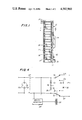
- FIG. 2 is a transverse sectional view thereof as seen from the plane 2--2 in FIG. 1.
- FIG. 3 is an exploded view in perspective of certain of the structure illustrated in FIG. 2.
- FIG. 4 is an electrical schematic wiring diagram.
- FIG. 5 is a fragmentary enlarged view in perspective corresponding to a left central portion of FIG. 3.
- the device generally indicated by reference character 10, comprises an outer housing element 11 including a base 12 having mounting brackets 13 for securing the same to a mounting surface (not shown). Extending outwardly from the base 12 are side walls 14 and 15, supporting an outer wall 15A, in turn mounting a conductor supporting element 16.
- the element 16 is preferably of molded synthetic resinous construction, and incorporates index means 17, as well as a centrally disposed recessed area 19 which mounts a plurality of quick clips 20 of well-known type.
- the outer ends 21 of the clips 20 may include the usual insulation displacement notches for engaging the ends of incoming subscriber pairs. Others of the clips 20 engage outoing pairs, again, as well known in the art. These clips communicate with a female connector 33 at the inner ends 22 thereof.
- Each element 30 includes a top wall 31 having a thickened portion 32 provided with guiding bores 33 which accommodate the inner ends of the clips 20.
- the wall 31 is supported by side walls 34 and 35 having screw means 36 to secure them to the side walls 14 and 15.
- the inner surfaces of the walls 34-35 are provided with oppositely facing internal grooves 37 for the slidable engagement of individual circuit board card elements generally indicated by reference character 30.
- the card elements 40 are, in essence, miniaturized circuit boards each including a mounting surface 41 and bounded by an upper edge 42, side edges 43 and 44, a lower edge 45, a medial edge 46 bordering a ground terminal 48, and a third side edge 49.
- the upper edge 42 includes a plurality of edge terminals 50 having resilient clip structure 51 adapted to engage the inner ends 22 of the clips 20. This is facilitated by an edge guide member 52 having corresponding bores 53.
- the card elements 40 mount a test circuit 54 (see FIG. 4) normally including a resister and a diode, and interconnected by a solid state latch means 55.
- An axially oriented ground assembly 58 (FIG. 3) includes a ground bus 59 mounting individual clips 16 which resiliently engage ground terminals 48.
- FIG. 4 there is illustrated a telephone operating company subscriber pair 64-65 eminating from an existing entry device 66 which determines a demarcation point.
- An optional customer reset circuit breaker 67 may be provided, and across the line is a direct current voltage detector 68 which operates the latch means 55.
- both legs 70 and 71 open the subscriber loop and interconnect the test circuit 54 whereby test procedures initiated at the telephone central office may be performed.
- the devices are activated (latched in until deactivated) by the application of a 130 volt direct current applied on the tip or ring side of the line.
- Required application time to ensure latching is three seconds at plus 130 volts and five seconds at plus 120 volts.
- the termination (signature) measurable from the test location with tip and ring normal is 5 megohms minimum. With tip and ring reversed it is 600 Ohms (nominal), because the circuit is polarized due to the action of the diode 76 in series with the resister 75.
- an optional fast volt protection is also provided of known type, and indicated by reference character 78. It includes a pair of Zener diode 79 and 80 and a ground connection 81.
Landscapes
- Engineering & Computer Science (AREA)
- Computer Networks & Wireless Communication (AREA)
- Signal Processing (AREA)
- Monitoring And Testing Of Exchanges (AREA)
Abstract
Description
Claims (5)
Priority Applications (1)
| Application Number | Priority Date | Filing Date | Title |
|---|---|---|---|
| US06/611,217 US4582960A (en) | 1984-05-17 | 1984-05-17 | Subscriber network interface device |
Applications Claiming Priority (1)
| Application Number | Priority Date | Filing Date | Title |
|---|---|---|---|
| US06/611,217 US4582960A (en) | 1984-05-17 | 1984-05-17 | Subscriber network interface device |
Publications (1)
| Publication Number | Publication Date |
|---|---|
| US4582960A true US4582960A (en) | 1986-04-15 |
Family
ID=24448102
Family Applications (1)
| Application Number | Title | Priority Date | Filing Date |
|---|---|---|---|
| US06/611,217 Expired - Lifetime US4582960A (en) | 1984-05-17 | 1984-05-17 | Subscriber network interface device |
Country Status (1)
| Country | Link |
|---|---|
| US (1) | US4582960A (en) |
Cited By (6)
| Publication number | Priority date | Publication date | Assignee | Title |
|---|---|---|---|---|
| WO1994001960A1 (en) * | 1992-07-01 | 1994-01-20 | Raychem Limited | Remotely actuated switch and protection circuit |
| US5359654A (en) * | 1992-05-12 | 1994-10-25 | Raychem Corporation | Telecommunications network interface assembly |
| US5652575A (en) * | 1992-07-01 | 1997-07-29 | Raychem Limited | Maintenance termination unit for telephone circuits |
| US6246749B1 (en) * | 1997-01-31 | 2001-06-12 | The Whitaker Corporation | Network interface unit and module |
| US7787614B2 (en) * | 2005-10-11 | 2010-08-31 | Corning Cable Systems Llc | Sealing current terminator for inhibiting oxidation and methods therefor |
| US20110043977A1 (en) * | 2009-01-05 | 2011-02-24 | Afl Telecommunications Llc | Universal mounting bracket |
Citations (15)
| Publication number | Priority date | Publication date | Assignee | Title |
|---|---|---|---|---|
| US3904839A (en) * | 1974-07-18 | 1975-09-09 | Bell Telephone Labor Inc | Loop fault locater |
| US4131934A (en) * | 1976-06-25 | 1978-12-26 | Siemens Aktiengesellschaft | Receptacle fixture for equipment units in electrical communication technology |
| US4143250A (en) * | 1976-12-13 | 1979-03-06 | Tii Corporation | Telephone isolation system |
| US4176257A (en) * | 1978-06-20 | 1979-11-27 | Porta Systems Corp. | Telephone connector block |
| US4229626A (en) * | 1979-08-01 | 1980-10-21 | Bell Telephone Laboratories, Incorporated | Loop fault sectionalization |
| US4242721A (en) * | 1977-10-20 | 1980-12-30 | Bunker Ramo Corporation | Electrical connector assembly for interconnecting remote signal stations to central signal processing systems |
| US4270030A (en) * | 1979-11-27 | 1981-05-26 | Bell Telephone Laboratories, Incorporated | Testing of subscriber loop pair gain systems |
| US4272141A (en) * | 1979-06-11 | 1981-06-09 | Frederick Electronics | Electronic card cage interfacing assembly |
| US4303296A (en) * | 1978-05-03 | 1981-12-01 | Bunker Ramo Corporation | Modular interface connector |
| US4373121A (en) * | 1981-06-15 | 1983-02-08 | Bell Telephone Laboratories, Incorporated | Maintenance termination device |
| US4451708A (en) * | 1981-04-03 | 1984-05-29 | Compagnie Industrielle Des Telecommunications Cit-Alcatel | Spare subscriber terminal apparatus |
| US4470102A (en) * | 1982-09-24 | 1984-09-04 | Porta Systems Corp. | Wall mounted distribution frame for telephone subscriber locations |
| US4485271A (en) * | 1982-07-30 | 1984-11-27 | Gk Technologies, Incorporated | Remotely actuable line disconnect device |
| US4488011A (en) * | 1983-05-27 | 1984-12-11 | Rogers M Maurice | On-premise telephone test jack |
| US4496057A (en) * | 1982-07-26 | 1985-01-29 | Fujitsu Limited | Rack structure for mounting a communication apparatus |
-
1984
- 1984-05-17 US US06/611,217 patent/US4582960A/en not_active Expired - Lifetime
Patent Citations (15)
| Publication number | Priority date | Publication date | Assignee | Title |
|---|---|---|---|---|
| US3904839A (en) * | 1974-07-18 | 1975-09-09 | Bell Telephone Labor Inc | Loop fault locater |
| US4131934A (en) * | 1976-06-25 | 1978-12-26 | Siemens Aktiengesellschaft | Receptacle fixture for equipment units in electrical communication technology |
| US4143250A (en) * | 1976-12-13 | 1979-03-06 | Tii Corporation | Telephone isolation system |
| US4242721A (en) * | 1977-10-20 | 1980-12-30 | Bunker Ramo Corporation | Electrical connector assembly for interconnecting remote signal stations to central signal processing systems |
| US4303296A (en) * | 1978-05-03 | 1981-12-01 | Bunker Ramo Corporation | Modular interface connector |
| US4176257A (en) * | 1978-06-20 | 1979-11-27 | Porta Systems Corp. | Telephone connector block |
| US4272141A (en) * | 1979-06-11 | 1981-06-09 | Frederick Electronics | Electronic card cage interfacing assembly |
| US4229626A (en) * | 1979-08-01 | 1980-10-21 | Bell Telephone Laboratories, Incorporated | Loop fault sectionalization |
| US4270030A (en) * | 1979-11-27 | 1981-05-26 | Bell Telephone Laboratories, Incorporated | Testing of subscriber loop pair gain systems |
| US4451708A (en) * | 1981-04-03 | 1984-05-29 | Compagnie Industrielle Des Telecommunications Cit-Alcatel | Spare subscriber terminal apparatus |
| US4373121A (en) * | 1981-06-15 | 1983-02-08 | Bell Telephone Laboratories, Incorporated | Maintenance termination device |
| US4496057A (en) * | 1982-07-26 | 1985-01-29 | Fujitsu Limited | Rack structure for mounting a communication apparatus |
| US4485271A (en) * | 1982-07-30 | 1984-11-27 | Gk Technologies, Incorporated | Remotely actuable line disconnect device |
| US4470102A (en) * | 1982-09-24 | 1984-09-04 | Porta Systems Corp. | Wall mounted distribution frame for telephone subscriber locations |
| US4488011A (en) * | 1983-05-27 | 1984-12-11 | Rogers M Maurice | On-premise telephone test jack |
Cited By (9)
| Publication number | Priority date | Publication date | Assignee | Title |
|---|---|---|---|---|
| US5359654A (en) * | 1992-05-12 | 1994-10-25 | Raychem Corporation | Telecommunications network interface assembly |
| WO1994001960A1 (en) * | 1992-07-01 | 1994-01-20 | Raychem Limited | Remotely actuated switch and protection circuit |
| US5604785A (en) * | 1992-07-01 | 1997-02-18 | Raychem Limited | Remotely actuated switch and protection circuit |
| US5652575A (en) * | 1992-07-01 | 1997-07-29 | Raychem Limited | Maintenance termination unit for telephone circuits |
| AU681587B2 (en) * | 1992-07-01 | 1997-09-04 | Raychem Limited | Remotely actuated switch and protection circuit |
| US6246749B1 (en) * | 1997-01-31 | 2001-06-12 | The Whitaker Corporation | Network interface unit and module |
| US7787614B2 (en) * | 2005-10-11 | 2010-08-31 | Corning Cable Systems Llc | Sealing current terminator for inhibiting oxidation and methods therefor |
| US20110043977A1 (en) * | 2009-01-05 | 2011-02-24 | Afl Telecommunications Llc | Universal mounting bracket |
| US8325494B2 (en) * | 2009-01-05 | 2012-12-04 | Afl Telecommunications Llc | Universal mounting bracket |
Similar Documents
| Publication | Publication Date | Title |
|---|---|---|
| US5297199A (en) | Apparatus for connecting and disconnecting subscriber premises line and incoming telephone company line | |
| KR101124185B1 (en) | Patch panel with modules | |
| US5333193A (en) | Telephone network termination module having insulation displacement terminals | |
| US6078661A (en) | Modular network interface device | |
| US6560334B1 (en) | Telephone subscriber line module | |
| US5416837A (en) | Telephone network interface enclosure | |
| US4364625A (en) | Electrical jack assembly | |
| US6062914A (en) | Circuit breaker plug in bracket and auxiliary/alarm switch connector for use therewith | |
| US5552962A (en) | Interconnect and cross-connect equipment including jack panel | |
| US6322375B1 (en) | Network interface device with circuit board architecture | |
| KR960006146A (en) | Safety connector | |
| US6229890B1 (en) | Network interface device with automatic connector closure | |
| US20050233640A1 (en) | Module-less cross connect assembly | |
| US5483573A (en) | Electric circuit connector with auto-termination | |
| US6917683B2 (en) | Signal splitter with test relays on auxiliary circuit board and system using same | |
| CN100594739C (en) | Patch board with modules | |
| US4582960A (en) | Subscriber network interface device | |
| EP0002266A1 (en) | A digital patch and access assembly comprising at least one digital patch and access module and a monitoring plug | |
| US6203334B1 (en) | Modular jack receptacle including a removable interface | |
| KR20040101288A (en) | A measurement arrangement and telecommunications assembly | |
| US7961846B2 (en) | Interface device for testing a telecommunication circuit | |
| US4752232A (en) | Locking device for telephone subscriber plugs | |
| US6882140B2 (en) | Network connection sensing assembly | |
| US6238250B1 (en) | In-jack shunt connections and methods therefor | |
| US20050105472A1 (en) | Test access matrix (TAM) protector module and associated circuitry for a telecommunications system |
Legal Events
| Date | Code | Title | Description |
|---|---|---|---|
| AS | Assignment |
Owner name: PORTA SYSTEMS CORP. SYOSSET, NY A DE CORP Free format text: ASSIGNMENT OF ASSIGNORS INTEREST.;ASSIGNORS:NEUWIRTH HELMUTH;DELUCA, PAUL V.;HUNG, PETER;REEL/FRAME:004261/0770 Effective date: 19840508 |
|
| STCF | Information on status: patent grant |
Free format text: PATENTED CASE |
|
| FEPP | Fee payment procedure |
Free format text: PAT HLDR NO LONGER CLAIMS SMALL ENT STAT AS SMALL BUSINESS (ORIGINAL EVENT CODE: LSM2); ENTITY STATUS OF PATENT OWNER: SMALL ENTITY |
|
| FPAY | Fee payment |
Year of fee payment: 4 |
|
| AS | Assignment |
Owner name: CHEMICAL BANK, NEW YORK Free format text: SECURITY INTEREST;ASSIGNOR:PORTA SYSTEMS;REEL/FRAME:006680/0415 Effective date: 19930624 |
|
| FPAY | Fee payment |
Year of fee payment: 8 |
|
| FEPP | Fee payment procedure |
Free format text: PAT HOLDER CLAIMS SMALL ENTITY STATUS - SMALL BUSINESS (ORIGINAL EVENT CODE: SM02); ENTITY STATUS OF PATENT OWNER: SMALL ENTITY |
|
| FPAY | Fee payment |
Year of fee payment: 12 |