US4582305A - Apparatus for cutting sheet material into predetermined shapes - Google Patents
Apparatus for cutting sheet material into predetermined shapes Download PDFInfo
- Publication number
- US4582305A US4582305A US06/705,583 US70558385A US4582305A US 4582305 A US4582305 A US 4582305A US 70558385 A US70558385 A US 70558385A US 4582305 A US4582305 A US 4582305A
- Authority
- US
- United States
- Prior art keywords
- cutting plate
- cutting
- plate
- holes
- guide grooves
- Prior art date
- Legal status (The legal status is an assumption and is not a legal conclusion. Google has not performed a legal analysis and makes no representation as to the accuracy of the status listed.)
- Expired - Fee Related
Links
Images

Classifications
-
- B—PERFORMING OPERATIONS; TRANSPORTING
- B25—HAND TOOLS; PORTABLE POWER-DRIVEN TOOLS; MANIPULATORS
- B25B—TOOLS OR BENCH DEVICES NOT OTHERWISE PROVIDED FOR, FOR FASTENING, CONNECTING, DISENGAGING OR HOLDING
- B25B11/00—Work holders not covered by any preceding group in the subclass, e.g. magnetic work holders, vacuum work holders
- B25B11/005—Vacuum work holders
-
- B—PERFORMING OPERATIONS; TRANSPORTING
- B23—MACHINE TOOLS; METAL-WORKING NOT OTHERWISE PROVIDED FOR
- B23D—PLANING; SLOTTING; SHEARING; BROACHING; SAWING; FILING; SCRAPING; LIKE OPERATIONS FOR WORKING METAL BY REMOVING MATERIAL, NOT OTHERWISE PROVIDED FOR
- B23D47/00—Sawing machines or sawing devices working with circular saw blades, characterised only by constructional features of particular parts
- B23D47/02—Sawing machines or sawing devices working with circular saw blades, characterised only by constructional features of particular parts of frames; of guiding arrangements for work-table or saw-carrier
- B23D47/025—Sawing machines or sawing devices working with circular saw blades, characterised only by constructional features of particular parts of frames; of guiding arrangements for work-table or saw-carrier of tables
Definitions
- the present invention concerns apparatus for holding and facilitating the cutting of translucent sheet material into predetermined sizes and shapes.
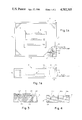
- FIGS. 1A and 1B are top and side elevation views respectively of the support frame of the present invention, having a fragment of the cutting plate of the present invention positioned thereon;
- FIGS. 2A and 2B are top and side elevation views respectively of the cutting plate of the present invention.
- FIG. 3 is a view of the cutting plate taken through the line A--A of FIG. 2A;
- FIG. 4 is a sectional view of the cutting plate illustrating alternative embodiments of the cutter guide grooves used in the present invention.
- FIGS. 1A and 1B of the drawings there is shown a support frame 2 comprising four upright side members 4 and a bottom member 6. Situated within the boxlike support frame 2 is a fluorescent light assembly 8. An exhaust port 10 protrudes from one of the side members 4 for connection of the plenum defined by the interior of the support structure 2 to a vacuum pump (not shown). A transparent (or translucent) cutting plate 12, a fragment of which is shown in FIGS. 1A and 1B, covers the top of support frame 2 and is backlighted by lighting assembly 8. Lighting assembly 8 is seen in FIG. 1A as being mounted on the upper surface of bottom member 6 and therefore within the plenum formed by the interior of the support frame 2. It can, however, if preferred, be contained in a cavity formed in bottom member 6, and be pneumatically isolated on the plenum area by sealing the cavity with a glass plate.
- the plate 12 which may be formed of a transparent or translucent material, is shown in greater detail.
- the upper surface of plate 12 has a number of V-shaped grooves 14 formed therein.
- the number and locations of the grooves 14 are such as to facilitate cutting of standard drawing sizes (e.g. B, C, D, E and F) from a plotted roll of paper. Only the grooves for three such drawing sizes are illustrated in FIG. 2A for the purpose of clarity.
- the drawings are cut to their correct margins or edges when the plotted drawing on the roll of paper is placed in alignment with inked, painted, or taped alignment lines 16 on the upper surface of cutting plate 12.
- the alignment lines 16 are of the proper dimensions to register with the printed border lines found approximately 0.5 inches within the outer edges of standard drawing size formats.
- the cutting grooves which serve to guide a cutting instrument may be nonlinear to accommodate an endless variety of shapes and sizes of patterns to be cut from a sheet or roll of translucent or transparent material.
- suction holes 20 are drilled through plate 12 on each side of, and along each groove 14.
- exhaust port 10 is connected to a vacuum pump, communication is provided between the underside of the paper placed atop plate 12 and the plenum chamber formed within the support frame 2. Atmospheric pressure then holds the sheet material during the cutting action.
- FIG. 3 is a view taken through the line A--A in FIG. 2A. It illustrates the cross-section of a pair of holes 20 positioned on opposite sides of a groove 14, and a sheet of material 22 positioned on the upper surface of cutting plate 12. It will be seen in FIG. 3 that the holes 20 are countersunk to provide an enlarged diameter at the end 24 thereof which protrudes through the upper surface of plate 12. The maximum diameter at the upper surface of cutting plate 12 is made several times that of the basic hole, to present a holding area at least several times that of the hole 20 alone. In effect, the holding-down power of each hole is multipled reducing the capacity of the vacuum pump required to adequately hold the paper 24 to the cutting plate 12.
- the corner of the cutting instrument such as a razor blade, for example, doesn't actually do the cutting of the paper. It pierces the paper, rides in the groove and lets the nearby edge do the cutting, thereby retaining the sharpness of cutting capability longer than if the point (corner) did the cutting. The point actually will become dull in time and rides the groove better if a little dull, since it then has less of a tendency to climb out of the groove 14.
- FIG. 4 illustrates alternate forms of grooves 14a, 14b and 14c.
- Groove 14a has a slot 26 with vertical walls formed at the vertex of the V-shaped cutter guide for further confining the sides of a cutting instrument.
- Any number of cutting tools are envisioned, as long as they will ride in a groove 14 for control. Variations may include knives of many shapes as well as a rolling knife. A rolling blade has merit in that it has less of a tendency to climb out of the groove.
- the cutting plate 12 may be attached to the support frame with suitable fasteners and gasket material may be provided therebetween. Although the suction holes 20 are shown only along the sides of each cutting groove, additional holes may be provided at other strategic locations on the plate 12 if they are needed. As previously mentioned the lighting assembly B may be sunken below the bottom member 6 and separated from the plenum chamber by a transparent window which additionally serves to seal the plenum from the outside atmosphere.
- suction holes 20 on both sides of each cutting groove serve to hold the overlying paper firmly against the cutting plate 12, even after the cuts have been made. Even with the suction on, to remove cuttings or the now-separated drawing, one need only peel back the material by lifting an edge or corner.
- the fluorescent light assembly 8 is shown in to be smaller than the bottom member 6, full length lights might be more suitable in certain applications.
Abstract
Description
Claims (6)
Priority Applications (1)
| Application Number | Priority Date | Filing Date | Title |
|---|---|---|---|
| US06/705,583 US4582305A (en) | 1985-02-26 | 1985-02-26 | Apparatus for cutting sheet material into predetermined shapes |
Applications Claiming Priority (1)
| Application Number | Priority Date | Filing Date | Title |
|---|---|---|---|
| US06/705,583 US4582305A (en) | 1985-02-26 | 1985-02-26 | Apparatus for cutting sheet material into predetermined shapes |
Publications (1)
| Publication Number | Publication Date |
|---|---|
| US4582305A true US4582305A (en) | 1986-04-15 |
Family
ID=24834107
Family Applications (1)
| Application Number | Title | Priority Date | Filing Date |
|---|---|---|---|
| US06/705,583 Expired - Fee Related US4582305A (en) | 1985-02-26 | 1985-02-26 | Apparatus for cutting sheet material into predetermined shapes |
Country Status (1)
| Country | Link |
|---|---|
| US (1) | US4582305A (en) |
Cited By (15)
| Publication number | Priority date | Publication date | Assignee | Title |
|---|---|---|---|---|
| US5332204A (en) * | 1989-04-11 | 1994-07-26 | Andersen Corporation | Hollow gasket welder |
| US5487536A (en) * | 1994-05-04 | 1996-01-30 | Mceachin; Jerry F. | Banner table |
| WO1996004102A1 (en) * | 1994-08-02 | 1996-02-15 | Tobias Michael Cardew | Vacuum securing arrangements |
| US5695600A (en) * | 1994-10-03 | 1997-12-09 | Goin; Bobby Gene | Vacuum table for decal weeding |
| US5792268A (en) * | 1993-07-02 | 1998-08-11 | Sci Systems, Inc. | Printered circuit board screen printer vacuum holding apparatus |
| US6240823B1 (en) * | 1998-11-24 | 2001-06-05 | Stephen J. Judge | Sheet material cutting system |
| US20010015919A1 (en) * | 1999-12-22 | 2001-08-23 | Kean Thomas A. | Method and apparatus for secure configuration of a field programmable gate array |
| DE102006009639A1 (en) * | 2006-03-02 | 2007-09-06 | Schott Ag | Vacuum clamping plate |
| CN102152402A (en) * | 2011-01-25 | 2011-08-17 | 黄桂芳 | Method for processing ultrathin stone slab and production process for composite plate of ultrathin stone slab |
| US20120073417A1 (en) * | 2009-06-15 | 2012-03-29 | Central Glass Company, Limited | Method and Device for Cutting a Sheet Material |
| CN103273445A (en) * | 2013-06-13 | 2013-09-04 | 中国科学院自动化研究所 | Clamping device and clamping method for thin and long parts |
| US20130247733A1 (en) * | 2012-03-22 | 2013-09-26 | Nhk Spring Co., Ltd. | Cutting jig and cutting apparatus for cutting plate material with rolling blade while holding plate material at each side of rolling blade |
| EP2886231A1 (en) * | 2013-12-17 | 2015-06-24 | MN Coil Servicecenter GmbH | Method of manufacturing a formed portion of a car body |
| CN107009528A (en) * | 2015-10-29 | 2017-08-04 | 三星显示有限公司 | Workbench for cutting substrate |
| US20190091818A1 (en) * | 2016-03-04 | 2019-03-28 | Homag Gmbh | Apparatus with extraction device |
Citations (8)
| Publication number | Priority date | Publication date | Assignee | Title |
|---|---|---|---|---|
| US2417149A (en) * | 1946-04-23 | 1947-03-11 | Beaton Elaine | Sewing frame |
| US2629924A (en) * | 1951-03-28 | 1953-03-03 | Frederick B Kauper | Instrument repair lighting table |
| US3588079A (en) * | 1968-09-30 | 1971-06-28 | Grace W R & Co | Negative mounting plate |
| US3840961A (en) * | 1973-03-23 | 1974-10-15 | R Brown | Apparatus for pneumatically securing backing to sheet material ancillary to folding or other operational treatment |
| US3848327A (en) * | 1970-12-09 | 1974-11-19 | Gerber Garment Technology Inc | Apparatus for working on sheet material |
| US4100676A (en) * | 1977-04-20 | 1978-07-18 | Ferguson Robert H | Pizza cutting board |
| US4116426A (en) * | 1977-03-01 | 1978-09-26 | Milton Kessler | Cutting board |
| US4475458A (en) * | 1983-06-02 | 1984-10-09 | Kennell Joseph F | Vacuum frame for offset printing plates |
-
1985
- 1985-02-26 US US06/705,583 patent/US4582305A/en not_active Expired - Fee Related
Patent Citations (8)
| Publication number | Priority date | Publication date | Assignee | Title |
|---|---|---|---|---|
| US2417149A (en) * | 1946-04-23 | 1947-03-11 | Beaton Elaine | Sewing frame |
| US2629924A (en) * | 1951-03-28 | 1953-03-03 | Frederick B Kauper | Instrument repair lighting table |
| US3588079A (en) * | 1968-09-30 | 1971-06-28 | Grace W R & Co | Negative mounting plate |
| US3848327A (en) * | 1970-12-09 | 1974-11-19 | Gerber Garment Technology Inc | Apparatus for working on sheet material |
| US3840961A (en) * | 1973-03-23 | 1974-10-15 | R Brown | Apparatus for pneumatically securing backing to sheet material ancillary to folding or other operational treatment |
| US4116426A (en) * | 1977-03-01 | 1978-09-26 | Milton Kessler | Cutting board |
| US4100676A (en) * | 1977-04-20 | 1978-07-18 | Ferguson Robert H | Pizza cutting board |
| US4475458A (en) * | 1983-06-02 | 1984-10-09 | Kennell Joseph F | Vacuum frame for offset printing plates |
Cited By (23)
| Publication number | Priority date | Publication date | Assignee | Title |
|---|---|---|---|---|
| US5332204A (en) * | 1989-04-11 | 1994-07-26 | Andersen Corporation | Hollow gasket welder |
| US5792268A (en) * | 1993-07-02 | 1998-08-11 | Sci Systems, Inc. | Printered circuit board screen printer vacuum holding apparatus |
| US5487536A (en) * | 1994-05-04 | 1996-01-30 | Mceachin; Jerry F. | Banner table |
| WO1996004102A1 (en) * | 1994-08-02 | 1996-02-15 | Tobias Michael Cardew | Vacuum securing arrangements |
| US5695600A (en) * | 1994-10-03 | 1997-12-09 | Goin; Bobby Gene | Vacuum table for decal weeding |
| US6240823B1 (en) * | 1998-11-24 | 2001-06-05 | Stephen J. Judge | Sheet material cutting system |
| US20010015919A1 (en) * | 1999-12-22 | 2001-08-23 | Kean Thomas A. | Method and apparatus for secure configuration of a field programmable gate array |
| DE102006009639A1 (en) * | 2006-03-02 | 2007-09-06 | Schott Ag | Vacuum clamping plate |
| WO2007098956A1 (en) * | 2006-03-02 | 2007-09-07 | Schott Ag | Vacuum clamping plate |
| US20120073417A1 (en) * | 2009-06-15 | 2012-03-29 | Central Glass Company, Limited | Method and Device for Cutting a Sheet Material |
| CN102802891B (en) * | 2009-06-15 | 2015-11-25 | 中央硝子株式会社 | The cutting method of sheet material and device |
| EP2444212A1 (en) * | 2009-06-15 | 2012-04-25 | Central Glass Company, Limited | Method and device for cutting a sheet material |
| CN102802891A (en) * | 2009-06-15 | 2012-11-28 | 中央硝子株式会社 | Method and device for cutting a sheet material |
| EP2444212A4 (en) * | 2009-06-15 | 2014-02-26 | Central Glass Co Ltd | Method and device for cutting a sheet material |
| CN102152402A (en) * | 2011-01-25 | 2011-08-17 | 黄桂芳 | Method for processing ultrathin stone slab and production process for composite plate of ultrathin stone slab |
| US20130247733A1 (en) * | 2012-03-22 | 2013-09-26 | Nhk Spring Co., Ltd. | Cutting jig and cutting apparatus for cutting plate material with rolling blade while holding plate material at each side of rolling blade |
| JP2013196749A (en) * | 2012-03-22 | 2013-09-30 | Nhk Spring Co Ltd | Cutting jig and cutting device for plate |
| US9233479B2 (en) * | 2012-03-22 | 2016-01-12 | Nhk Spring Co., Ltd. | Cutting jig and cutting apparatus for cutting plate material with rolling blade while holding plate material at each side of rolling blade |
| CN103273445A (en) * | 2013-06-13 | 2013-09-04 | 中国科学院自动化研究所 | Clamping device and clamping method for thin and long parts |
| CN103273445B (en) * | 2013-06-13 | 2015-02-11 | 中国科学院自动化研究所 | Clamping device and clamping method for thin and long parts |
| EP2886231A1 (en) * | 2013-12-17 | 2015-06-24 | MN Coil Servicecenter GmbH | Method of manufacturing a formed portion of a car body |
| CN107009528A (en) * | 2015-10-29 | 2017-08-04 | 三星显示有限公司 | Workbench for cutting substrate |
| US20190091818A1 (en) * | 2016-03-04 | 2019-03-28 | Homag Gmbh | Apparatus with extraction device |
Similar Documents
| Publication | Publication Date | Title |
|---|---|---|
| US4582305A (en) | Apparatus for cutting sheet material into predetermined shapes | |
| US6321457B1 (en) | Cutting template and method of using same | |
| US4543862A (en) | Vacuum die cutting apparatus for foam backed materials | |
| SE8306623D0 (en) | ROTATING STANDING PROCEDURES FOR REPAIRING WINDOWS IN CARTRIDGES | |
| US5058285A (en) | Template | |
| ATE65960T1 (en) | HOLDER FOR A CUTTING PLATE FOR CUTTING FIELDS. | |
| CN110355821B (en) | Opposite-pasting knife printing process for correcting automatically arranged products | |
| EP0433503A1 (en) | Vacuum chuck | |
| US4505044A (en) | Drawing aid with interchangeable insert | |
| US3572202A (en) | Sheet material cutter with presser plate utilizing pressurized air | |
| US4607442A (en) | Slide mount | |
| DE68912188D1 (en) | Device for cutting tapes. | |
| DE68907760T2 (en) | Punch knife. | |
| US20020011140A1 (en) | Cutting die clamping mechanism | |
| CN219748298U (en) | FPC classification cutter | |
| US3290975A (en) | Method of re-registry of negatives and the like | |
| US4870756A (en) | Strip cutter | |
| CN218785619U (en) | Positioning ruler plate of perforating machine | |
| KR970014955A (en) | Corner cutter | |
| SE8502938D0 (en) | MAKE SIZE A STACK OF SHEET MATERIAL | |
| CN113650076A (en) | Light guide plate processing equipment | |
| CN213739175U (en) | Bearing jig for glass cutting | |
| CN213002390U (en) | Cutting mechanism for coil | |
| CN217799298U (en) | Vacuum adsorption cuts frock | |
| JPH10175199A (en) | Punching edge |
Legal Events
| Date | Code | Title | Description |
|---|---|---|---|
| AS | Assignment |
Owner name: GLIDDEN COMPANY, THE, 925 EUCLID AVENUE, CLEVELAND Free format text: ASSIGNMENT OF ASSIGNORS INTEREST.;ASSIGNOR:SCM CORPORATION;REEL/FRAME:004858/0717 Effective date: 19861028 Owner name: GLIDDEN COMPANY, THE, A CORP. OF DE., OHIO Free format text: ASSIGNMENT OF ASSIGNORS INTEREST;ASSIGNOR:SCM CORPORATION;REEL/FRAME:004858/0717 Effective date: 19861028 |
|
| AS | Assignment |
Owner name: GOVERNMENT OF THE UNITED STATES OF AMERICA, AS REP Free format text: ASSIGNMENT OF ASSIGNORS INTEREST.;ASSIGNOR:BROTHERS, JACK;REEL/FRAME:004737/0043 Effective date: 19860715 |
|
| FPAY | Fee payment |
Year of fee payment: 4 |
|
| REMI | Maintenance fee reminder mailed | ||
| LAPS | Lapse for failure to pay maintenance fees | ||
| FP | Expired due to failure to pay maintenance fee |
Effective date: 19940628 |
|
| STCH | Information on status: patent discontinuation |
Free format text: PATENT EXPIRED DUE TO NONPAYMENT OF MAINTENANCE FEES UNDER 37 CFR 1.362 |