US4509937A - Power transmission chain - Google Patents
Power transmission chain Download PDFInfo
- Publication number
- US4509937A US4509937A US06/546,667 US54666783A US4509937A US 4509937 A US4509937 A US 4509937A US 54666783 A US54666783 A US 54666783A US 4509937 A US4509937 A US 4509937A
- Authority
- US
- United States
- Prior art keywords
- links
- sets
- flanks
- link
- back surface
- Prior art date
- Legal status (The legal status is an assumption and is not a legal conclusion. Google has not performed a legal analysis and makes no representation as to the accuracy of the status listed.)
- Expired - Lifetime
Links
- 230000005540 biological transmission Effects 0.000 title claims abstract description 8
- 210000003371 toe Anatomy 0.000 claims description 8
- 239000000203 mixture Substances 0.000 abstract description 4
- RAQQRQCODVNJCK-JLHYYAGUSA-N N-[(4-amino-2-methylpyrimidin-5-yl)methyl]-N-[(E)-5-hydroxy-3-(2-hydroxyethyldisulfanyl)pent-2-en-2-yl]formamide Chemical compound C\C(N(Cc1cnc(C)nc1N)C=O)=C(\CCO)SSCCO RAQQRQCODVNJCK-JLHYYAGUSA-N 0.000 abstract 1
- 230000004048 modification Effects 0.000 description 3
- 238000012986 modification Methods 0.000 description 3
- 230000004075 alteration Effects 0.000 description 2
- 230000003287 optical effect Effects 0.000 description 2
- 230000002285 radioactive effect Effects 0.000 description 2
- 229910000831 Steel Inorganic materials 0.000 description 1
- 238000003491 array Methods 0.000 description 1
- 239000013065 commercial product Substances 0.000 description 1
- 238000001514 detection method Methods 0.000 description 1
- 239000012467 final product Substances 0.000 description 1
- 238000007689 inspection Methods 0.000 description 1
- 230000005415 magnetization Effects 0.000 description 1
- 238000004519 manufacturing process Methods 0.000 description 1
- 239000003973 paint Substances 0.000 description 1
- 230000000704 physical effect Effects 0.000 description 1
- 239000011435 rock Substances 0.000 description 1
- 238000001228 spectrum Methods 0.000 description 1
- 239000010959 steel Substances 0.000 description 1
Images


Classifications
-
- F—MECHANICAL ENGINEERING; LIGHTING; HEATING; WEAPONS; BLASTING
- F16—ENGINEERING ELEMENTS AND UNITS; GENERAL MEASURES FOR PRODUCING AND MAINTAINING EFFECTIVE FUNCTIONING OF MACHINES OR INSTALLATIONS; THERMAL INSULATION IN GENERAL
- F16G—BELTS, CABLES, OR ROPES, PREDOMINANTLY USED FOR DRIVING PURPOSES; CHAINS; FITTINGS PREDOMINANTLY USED THEREFOR
- F16G13/00—Chains
- F16G13/02—Driving-chains
- F16G13/04—Toothed chains
-
- B—PERFORMING OPERATIONS; TRANSPORTING
- B21—MECHANICAL METAL-WORKING WITHOUT ESSENTIALLY REMOVING MATERIAL; PUNCHING METAL
- B21L—MAKING METAL CHAINS
- B21L9/00—Making chains or chain links, the links being composed of two or more different parts, e.g. drive chains
- B21L9/02—Making chains or chain links, the links being composed of two or more different parts, e.g. drive chains of roller-chain or other plate-link type
- B21L9/06—Sorting, feeding, assembling, riveting, or finishing parts of chains
Definitions
- Power transmission chains composed of pivotably connected sets of interleaved links are known in the art.
- each of the links which drivingly engage the teeth of a sprocket is defined by a pair of toes, each toe being at the juncture of an inside flank and an outside flank. The inside flanks are joined by a crotch.
- the backs of these links are generally arcuate or curved.
- each set of links is not uniform, the amount of noise reduction is not as great. That is, if one inside flank engagement link is positioned with a plurality of outside flank engagement links to form one set of links, there is a noticeable increase in the noise level when the chain operates.
- the assembly of uniform ranks or sets of links has proved difficult because the physical difference between the inside flank engagement and outside flank engagement links are physically and visually very small, and do not admit of ready detection by automatic sorting apparatus.
- It is therefore a primary object of the present invention is to provide a power transmission chain of the type generally described in the above-identified application, but in which each link has some physical characteristic (other than its flank profile) which readily identifies the links as either an inside flank or outside flank engagement link.
- the two types of links making up the chain are configured to have a physical characteristic such that they are distinguishable from one another.
- the physical characteristic modified is the back surface shape, where the back surface is that farthest from the toes.
- the links can be visually, electrically, mechanically, optically, or otherwise inspected to identify and separate the different link types.
- One of the link types in the preferred embodiment has an arcuate or curved back surface while the other type of link has a generally flat, planar surface. The ends of the latter can be angled if so desired.
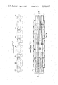
- FIG. 1 is a side view of a portion of a chain and a toothed sprocket, with parts broken away incorporating two types of links according to this invention
- FIG. 2 is a side view of a portion of a typical chain according to this invention, also with parts broken away;
- FIG. 3 is a plan view of the portion of the chain of FIG. 2;
- FIG. 4 is a side view of one form of link in the chain of FIGS. 1-3;
- FIG. 5 is a side view of another form of link in the chain of FIGS. 1-3;
- FIG. 6 is a side view of an alternate form of usuable in the chain of FIGS. 1-3;
- FIG. 7 is a plan view similar to FIG. 3 but showing a chain with some links out of place.
- FIG. 8 is a schematic illustration of an optically-based system for detecting the presence and location of "out-of-place" links in a chain.
- FIGS. 1-3 illustrate a portion of an endless power transmission chain 10 and a toothed sprocket 12 with teeth 14, the chain being composed of sets 16 and 18 of links 20 and 22, the links 20 and 22 being different in shape as better illustrated in FIGS. 4 and 5.
- the links 20 of sets 16 are stippled to further distinguish them from the links 22 of sets 18.
- the sets 16 and 18 of links are pivotably interconnected by pivot means 24, shown as round pins.
- a pin and rocker joint in which one member rocks on another, as known in the art, can be used if so desired.
- guide links 26 which are provided along the outside of the chain to maintain sprocket tooth-chain engagement. The guide links do not drivingly engage the sprocket teeth.
- the illustrated guide links 26 are outside guide links and flank the sprocket teeth. Inside guide links (not shown) which ride in a sprocket groove can be used if desired.
- FIG. 4 shows one link 20 having a pair of toes 28,28, each defined by diverging flanks 30, 32, the flanks 30 being outside flanks and the flanks 32 being inside flanks.
- the flanks 32 are joined by a crotch 34.
- the back of the link is a flat surface 36. It will become apparent that flat back surface 36 of link 20 is the physical characteristic modfified (flattened) to identify link 20.
- the flanks are generally straight.
- Apertures 38, 38 are provided to receive pins or the pin-rocker joint. This link drivingly contacts the sprocket teeth with the outside flanks.
- FIG. 5 shows a link 22 having a pair of toes 40, 40, each defined by diverging flanks 42, 44, the flanks 42 being generally straight outside flanks and the flanks 44 being arcuate inside flanks.
- the flanks 44 are joined by a crotch 46.
- the back of the link is an arcuate surface 48.
- Apertures 50, 50 are provided in the link to receive the pins or pin-rocker joints.
- the links 22 drivingly contact the sprocket teeth with their inside flanks.
- the link 60 illustrated in FIG. 6 is an alternate form of the link 20 of FIG. 4.
- the link 60 has toes 62 defined by diverging outside flanks 64 and inside flanks 66, the flanks 66 being joined by a crotch 68.
- the back of the links has a flat surface 70 and angled end surfaces 72; apertures 74, 74 are provided to receive the pivot means.
- the inside flank engaging link could be provided with a flat back, and the outside flank engaging link could be provided with the arcuate back without departing from the spirit of the invention.
- other physical characteristics can be modified to identify the inside or outside flank engagement of each link. For example, all inside flank engagement links can be sprayed with a paint having a color different than that sprayed on other types of links. The finished links can then be illuminated by a light, the reflected light detected and, after examination for the apropriate color spectrum, the link type verified.
- links of a given type can be magnetized or irridated with a low level of radioactive energy, and the resultant links identified by the presence or absence of the magnetization or the radioactive emission. It has been found most practical and economical to utilize a simple physical modification, such as the shape of the link back surface, in the implementation of this invention.
- FIG. 7 A chain with some links wrongly located is illustrated in FIG. 7.
- the links 20, those without outside flank engagement and the flat backs, are stippled to distinguish them from links 22, the inside flank engagement links with curved backs.
- the two out-of-place links are readily apparent in FIG. 7. A chain with such out-of-place links will be rejected and then brought into specification by substituting the proper links or sets of links in the assembly.
- the links are stamped from sheet steel, treated to improve their physical properties, and ultimately assembled into the final product.
- the links are transported from the forming to the assembly positons in bins which may hold several thousand links. It thus becomes easy to intermix the link types, especially when the link thickness and pitch (the distance between pivot means centers) are the same.
- the links are fed into automatic assembling machines, which assemble the sets of links in a relatively long length of chain. Sections of the relatively long length of chain are broken-out into segments of predetermined length, and the ends of each segment are joined by a pivot means to form the chain loops usuable in a sprocket drive.
- the automatic assembling machines are adjusted to handle only one type of link and to reject the other, and to assemble the uniform sets of links in the desired fashion, such as in a random mixture of sets or in a particular arrangement of sets. Even when the machines are adjusted to reject the wrong link, at times the wrong link type "sneaks" through.
- the links with a modified physical characteristic as taught herein the erroneous link can be easily detected, and the correction made.
- FIG. 8 illustrates, schematically, an optical device for detecting the presence and location of "out-of-place" links in a set of links.
- the chain is conveyed in a generally horizontal path beneath a transverse series of light sources 80 positoned to direct a light toward the back of the chain 10, so some light is reflected from the chain's back surface.
- the differently configured backs of the links will reflect light differently.
- Light is reflected from flat surfaces 36 of links 20 in a relatively narrow, cylindrical beam which impinges only on a first array of sensors 82.
- Light is reflective from curved surfaces 48 of links 22 in a much broader, diverging beam which strikes arrays of both pickups, 82 and 84.
- the reflected light is picked-up by sensors or pick devices 82, 84, which are connected to an indicator or recording devices 86 which visually, audibly or otherwise indicates the link mixture.
- An out-of-place link is indicated by an incorrect reflected signal.
- Device 86 is electrically coupled to a motor 88 of the conveyor drive system. The signal for an out-of-place link can de-energize motor 88 and stop the conveyor, and/or the location of the out-of-place link can be marked for later correction.
- a mechanical, electro-mechanical or pneumatic inspection device can be provided in lieu of the optical system described. These can use feelers, either in a pure mechanical system or in an electro-mechanical system, or air jets in a pneumatic system.
- a "set" of links means a group of links disposed in one row or rank transversely across the width of the chain, and connected by two adjacent pivot means.
- a single set of links with each link aligned one behind the other, would appear similar to the single link 20 in FIG. 4 or the single link 22 in FIG. 5.
- a first pivot would be inserted into one of the apertures 38 of each of the links 20 in the set, and a second pivot or rod would be inserted into the other apertures 38 of the same set of links.
Abstract
Description
Claims (3)
Priority Applications (1)
| Application Number | Priority Date | Filing Date | Title |
|---|---|---|---|
| US06/546,667 US4509937A (en) | 1981-12-18 | 1983-10-28 | Power transmission chain |
Applications Claiming Priority (2)
| Application Number | Priority Date | Filing Date | Title |
|---|---|---|---|
| US33203281A | 1981-12-18 | 1981-12-18 | |
| US06/546,667 US4509937A (en) | 1981-12-18 | 1983-10-28 | Power transmission chain |
Related Parent Applications (1)
| Application Number | Title | Priority Date | Filing Date |
|---|---|---|---|
| US33203281A Continuation | 1981-12-18 | 1981-12-18 |
Publications (1)
| Publication Number | Publication Date |
|---|---|
| US4509937A true US4509937A (en) | 1985-04-09 |
Family
ID=26988030
Family Applications (1)
| Application Number | Title | Priority Date | Filing Date |
|---|---|---|---|
| US06/546,667 Expired - Lifetime US4509937A (en) | 1981-12-18 | 1983-10-28 | Power transmission chain |
Country Status (1)
| Country | Link |
|---|---|
| US (1) | US4509937A (en) |
Cited By (35)
| Publication number | Priority date | Publication date | Assignee | Title |
|---|---|---|---|---|
| EP0178818A2 (en) * | 1984-10-17 | 1986-04-23 | Borg-Warner Automotive, Inc. | Power transmission chain |
| US4758210A (en) * | 1987-04-01 | 1988-07-19 | Borg-Warner Automotive, Inc. | Silent chain and sprocket system |
| US5090948A (en) * | 1990-03-20 | 1992-02-25 | Borg-Warner Automotive Transmission & Engine Components Corporation | Chain belt power transmission |
| US5154674A (en) * | 1990-04-25 | 1992-10-13 | Borg-Warner Automotive Transmission & Engine Components Corporation | Power transmission chain constructed with asymmetrical links |
| US5445570A (en) * | 1994-02-15 | 1995-08-29 | Borg-Warner Automotive, Inc. | Chain guide link |
| US5758484A (en) * | 1996-09-30 | 1998-06-02 | Borg-Warner Automotive, Inc. | Silent chain with raised link backs |
| EP0852305A1 (en) | 1997-01-06 | 1998-07-08 | Borg-Warner Automotive, Inc. | Backdrive silent chain and sprocket |
| US5921879A (en) * | 1996-07-25 | 1999-07-13 | Cloyes Gear And Products, Inc. | Random engagement roller chain sprocket with staged meshing and flank relief to provide improved noise characteristics |
| WO1999040342A1 (en) * | 1998-02-10 | 1999-08-12 | Cloyes Gear And Products, Inc. | Short pitch tooth chain |
| US5976045A (en) * | 1996-07-25 | 1999-11-02 | Cloyes Gear And Products, Inc. | Random engagement roller chain sprocket having improved noise characteristics |
| US6090003A (en) * | 1996-07-25 | 2000-07-18 | Cloyes Gear & Products, Inc. | Random engagement roller chain sprocket having improved noise characteristics |
| US6244983B1 (en) | 1998-08-21 | 2001-06-12 | Borg-Warner Automotive K.K. | Silent chain with inner flank engagement links and sprocket having teeth with matching surfaces |
| US6364800B1 (en) * | 1998-09-21 | 2002-04-02 | Borgwarner Inc. | Interior guided chain system for lateral chain control |
| GB2373306A (en) * | 2001-02-23 | 2002-09-18 | Tsubakimoto Chain Co | Silent chain having a random arrangement of link plate types |
| US6478704B1 (en) * | 1999-09-09 | 2002-11-12 | Luk Lamellen Und Kupplungsbau Beteiligungs Kg | Link chain |
| US6612103B2 (en) | 2000-07-27 | 2003-09-02 | Borgwarner Morse Tec Japan K.K. | Link plate for a silent chain |
| US6761657B2 (en) | 1996-12-19 | 2004-07-13 | Cloyes Gear And Products, Inc. | Roller chain sprocket with added chordal pitch reduction |
| US20040185977A1 (en) * | 1996-12-19 | 2004-09-23 | Cloyes Gear And Products, Inc. | Random engagement roller chain sprocket and timing chain system including same |
| US6969332B2 (en) * | 2000-06-05 | 2005-11-29 | Borg-Warner Automotive K.K. | Silent chain |
| US20060068959A1 (en) * | 2004-09-24 | 2006-03-30 | Young James D | Inverted tooth chain system with inside flank engagement |
| US7059985B2 (en) * | 2001-07-17 | 2006-06-13 | Borgwarner Inc. | Alternating guide power transmission chain |
| US7175648B2 (en) * | 2003-11-18 | 2007-02-13 | Granit Medical Innovations, Llc | Deep endoscopic staple and stapler |
| US20080020881A1 (en) * | 2006-07-21 | 2008-01-24 | Luk Lamellen Und Kupplungsbau Beteiligungs Kg | Chain for driving a component |
| US20080300079A1 (en) * | 2004-07-06 | 2008-12-04 | Schaeffler Kg | Silent Chain |
| US20090042683A1 (en) * | 2007-08-08 | 2009-02-12 | Tsubakimoto Chain Co. | Silent chain |
| US20110021299A1 (en) * | 2008-09-09 | 2011-01-27 | Young James D | Inverted Tooth Chain and Sprocket Drive System with Reduced Meshing Impact |
| US20110183799A1 (en) * | 2008-09-09 | 2011-07-28 | Young James D | Inverted tooth chain and sprocket drive system with reduced meshing impact |
| US20110230289A1 (en) * | 2010-03-18 | 2011-09-22 | Schaeffler Technologies Gmbh & Co. Kg | Double-sided inverted tooth chain |
| US8628440B2 (en) | 2008-09-09 | 2014-01-14 | Cloyes Gear And Products, Inc. | Inverted tooth chain and sprocket drive system with reduced meshing impact |
| US20140338620A1 (en) * | 2013-05-16 | 2014-11-20 | Iwis Motorsysteme Gmbh & Co. Kg | Marking labels for drive chains |
| US20160053853A1 (en) * | 2014-08-22 | 2016-02-25 | Schaeffler Technologies AG & Co. KG | High strength inverted tooth chain having a press-fit middle plate |
| US9377082B2 (en) | 2008-09-09 | 2016-06-28 | Cloyes Gear And Products, Inc. | Inverted tooth chain and sprocket drive system with reduced meshing impact |
| US20160223053A1 (en) * | 2015-02-03 | 2016-08-04 | Iwis Motorsysteme Gmbh & Co. Kg | Articulated chain with low-friction link plate back |
| US10001207B1 (en) * | 2017-10-02 | 2018-06-19 | Borgwarner Inc. | Tertiary chain lacing assembly |
| US20220003295A1 (en) * | 2019-03-22 | 2022-01-06 | Daido Kogyo Co., Ltd. | Chain transmission device |
Citations (6)
| Publication number | Priority date | Publication date | Assignee | Title |
|---|---|---|---|---|
| US1422527A (en) * | 1920-01-20 | 1922-07-11 | Frederick L Sawyer | Color print viewable by lights of different colors and process of making the same |
| US1480528A (en) * | 1922-09-16 | 1924-01-08 | Morse Chain Co | Drive chain |
| US2667791A (en) * | 1950-12-23 | 1954-02-02 | Morse Chain Co | Silent chain |
| US3340745A (en) * | 1965-11-15 | 1967-09-12 | Acme Chain Corp | Vibrationless timing chain |
| US4051949A (en) * | 1976-05-17 | 1977-10-04 | The Laitram Corporation | Conveyor system |
| US4342560A (en) * | 1980-05-16 | 1982-08-03 | Borg-Warner Corporation | Composite chain link assembly |
-
1983
- 1983-10-28 US US06/546,667 patent/US4509937A/en not_active Expired - Lifetime
Patent Citations (6)
| Publication number | Priority date | Publication date | Assignee | Title |
|---|---|---|---|---|
| US1422527A (en) * | 1920-01-20 | 1922-07-11 | Frederick L Sawyer | Color print viewable by lights of different colors and process of making the same |
| US1480528A (en) * | 1922-09-16 | 1924-01-08 | Morse Chain Co | Drive chain |
| US2667791A (en) * | 1950-12-23 | 1954-02-02 | Morse Chain Co | Silent chain |
| US3340745A (en) * | 1965-11-15 | 1967-09-12 | Acme Chain Corp | Vibrationless timing chain |
| US4051949A (en) * | 1976-05-17 | 1977-10-04 | The Laitram Corporation | Conveyor system |
| US4342560A (en) * | 1980-05-16 | 1982-08-03 | Borg-Warner Corporation | Composite chain link assembly |
Cited By (50)
| Publication number | Priority date | Publication date | Assignee | Title |
|---|---|---|---|---|
| EP0178818A3 (en) * | 1984-10-17 | 1986-11-05 | Borg-Warner Corporation | Power transmission chain |
| EP0178818A2 (en) * | 1984-10-17 | 1986-04-23 | Borg-Warner Automotive, Inc. | Power transmission chain |
| US4758210A (en) * | 1987-04-01 | 1988-07-19 | Borg-Warner Automotive, Inc. | Silent chain and sprocket system |
| US5090948A (en) * | 1990-03-20 | 1992-02-25 | Borg-Warner Automotive Transmission & Engine Components Corporation | Chain belt power transmission |
| US5154674A (en) * | 1990-04-25 | 1992-10-13 | Borg-Warner Automotive Transmission & Engine Components Corporation | Power transmission chain constructed with asymmetrical links |
| US5445570A (en) * | 1994-02-15 | 1995-08-29 | Borg-Warner Automotive, Inc. | Chain guide link |
| US5976045A (en) * | 1996-07-25 | 1999-11-02 | Cloyes Gear And Products, Inc. | Random engagement roller chain sprocket having improved noise characteristics |
| US6090003A (en) * | 1996-07-25 | 2000-07-18 | Cloyes Gear & Products, Inc. | Random engagement roller chain sprocket having improved noise characteristics |
| US5921879A (en) * | 1996-07-25 | 1999-07-13 | Cloyes Gear And Products, Inc. | Random engagement roller chain sprocket with staged meshing and flank relief to provide improved noise characteristics |
| US5758484A (en) * | 1996-09-30 | 1998-06-02 | Borg-Warner Automotive, Inc. | Silent chain with raised link backs |
| US7416500B2 (en) | 1996-12-19 | 2008-08-26 | Cloyes Gear And Products, Inc. | Random engagement roller chain sprocket and timing chain system including same |
| US6761657B2 (en) | 1996-12-19 | 2004-07-13 | Cloyes Gear And Products, Inc. | Roller chain sprocket with added chordal pitch reduction |
| US20040185977A1 (en) * | 1996-12-19 | 2004-09-23 | Cloyes Gear And Products, Inc. | Random engagement roller chain sprocket and timing chain system including same |
| US6325734B1 (en) | 1996-12-19 | 2001-12-04 | Cloyes Gear And Products, Inc. | Random engagement roller chain sprocket with staged meshing and flank relief to provide improved noise characteristics |
| EP0852305A1 (en) | 1997-01-06 | 1998-07-08 | Borg-Warner Automotive, Inc. | Backdrive silent chain and sprocket |
| US6186920B1 (en) | 1998-02-10 | 2001-02-13 | Cloyes Gear And Products, Inc. | Short pitch tooth chain |
| WO1999040342A1 (en) * | 1998-02-10 | 1999-08-12 | Cloyes Gear And Products, Inc. | Short pitch tooth chain |
| US6244983B1 (en) | 1998-08-21 | 2001-06-12 | Borg-Warner Automotive K.K. | Silent chain with inner flank engagement links and sprocket having teeth with matching surfaces |
| US6364800B1 (en) * | 1998-09-21 | 2002-04-02 | Borgwarner Inc. | Interior guided chain system for lateral chain control |
| US6478704B1 (en) * | 1999-09-09 | 2002-11-12 | Luk Lamellen Und Kupplungsbau Beteiligungs Kg | Link chain |
| US6969332B2 (en) * | 2000-06-05 | 2005-11-29 | Borg-Warner Automotive K.K. | Silent chain |
| US6612103B2 (en) | 2000-07-27 | 2003-09-02 | Borgwarner Morse Tec Japan K.K. | Link plate for a silent chain |
| GB2373306A (en) * | 2001-02-23 | 2002-09-18 | Tsubakimoto Chain Co | Silent chain having a random arrangement of link plate types |
| US6663522B2 (en) | 2001-02-23 | 2003-12-16 | Tsubakimoto Chain Co. | Random arrangement type silent chain |
| GB2373306B (en) * | 2001-02-23 | 2004-07-14 | Tsubakimoto Chain Co | Random arrangement type silent chain |
| US7059985B2 (en) * | 2001-07-17 | 2006-06-13 | Borgwarner Inc. | Alternating guide power transmission chain |
| US7175648B2 (en) * | 2003-11-18 | 2007-02-13 | Granit Medical Innovations, Llc | Deep endoscopic staple and stapler |
| US20080300079A1 (en) * | 2004-07-06 | 2008-12-04 | Schaeffler Kg | Silent Chain |
| US20060068959A1 (en) * | 2004-09-24 | 2006-03-30 | Young James D | Inverted tooth chain system with inside flank engagement |
| US7789783B2 (en) * | 2004-09-24 | 2010-09-07 | Cloyes Gear And Products, Inc. | Inverted tooth chain system with inside flank engagement |
| US20080020881A1 (en) * | 2006-07-21 | 2008-01-24 | Luk Lamellen Und Kupplungsbau Beteiligungs Kg | Chain for driving a component |
| WO2008009259A1 (en) * | 2006-07-21 | 2008-01-24 | Schaeffler Kg | Chain for driving a component |
| US20090042683A1 (en) * | 2007-08-08 | 2009-02-12 | Tsubakimoto Chain Co. | Silent chain |
| JP2009041630A (en) * | 2007-08-08 | 2009-02-26 | Tsubakimoto Chain Co | Silent chain |
| US7837583B2 (en) * | 2007-08-08 | 2010-11-23 | Tsubakimoto Chain Co. | Silent chain |
| DE102008033900B4 (en) * | 2007-08-08 | 2014-05-22 | Tsubakimoto Chain Co. | Low-noise chain |
| US8529389B2 (en) | 2008-09-09 | 2013-09-10 | Cloyes Gear And Products, Inc. | Inverted tooth chain and sprocket drive system with reduced meshing impact |
| US9377082B2 (en) | 2008-09-09 | 2016-06-28 | Cloyes Gear And Products, Inc. | Inverted tooth chain and sprocket drive system with reduced meshing impact |
| US20110183799A1 (en) * | 2008-09-09 | 2011-07-28 | Young James D | Inverted tooth chain and sprocket drive system with reduced meshing impact |
| US8628440B2 (en) | 2008-09-09 | 2014-01-14 | Cloyes Gear And Products, Inc. | Inverted tooth chain and sprocket drive system with reduced meshing impact |
| US8672786B2 (en) | 2008-09-09 | 2014-03-18 | Cloyes Gear And Products, Inc. | Inverted tooth chain and sprocket drive system with reduced meshing impact |
| US20110021299A1 (en) * | 2008-09-09 | 2011-01-27 | Young James D | Inverted Tooth Chain and Sprocket Drive System with Reduced Meshing Impact |
| US20110230289A1 (en) * | 2010-03-18 | 2011-09-22 | Schaeffler Technologies Gmbh & Co. Kg | Double-sided inverted tooth chain |
| US20140338620A1 (en) * | 2013-05-16 | 2014-11-20 | Iwis Motorsysteme Gmbh & Co. Kg | Marking labels for drive chains |
| US20160053853A1 (en) * | 2014-08-22 | 2016-02-25 | Schaeffler Technologies AG & Co. KG | High strength inverted tooth chain having a press-fit middle plate |
| US20160223053A1 (en) * | 2015-02-03 | 2016-08-04 | Iwis Motorsysteme Gmbh & Co. Kg | Articulated chain with low-friction link plate back |
| US9856942B2 (en) * | 2015-02-03 | 2018-01-02 | Iwis Motorsysteme Gmbh & Co. Kg | Articulated chain with low-friction link plate back |
| US10001207B1 (en) * | 2017-10-02 | 2018-06-19 | Borgwarner Inc. | Tertiary chain lacing assembly |
| US20220003295A1 (en) * | 2019-03-22 | 2022-01-06 | Daido Kogyo Co., Ltd. | Chain transmission device |
| US11927244B2 (en) * | 2019-03-22 | 2024-03-12 | Daido Kogyo Co., Ltd. | Chain transmission device |
Similar Documents
| Publication | Publication Date | Title |
|---|---|---|
| US4509937A (en) | Power transmission chain | |
| US4509323A (en) | Power transmission chain | |
| US5154674A (en) | Power transmission chain constructed with asymmetrical links | |
| EP1939795B1 (en) | Egg counter for counting eggs transferred by egg collection conveyer | |
| US5646724A (en) | Threaded parts inspection device | |
| US4832668A (en) | Power transmission chain | |
| US5236400A (en) | Silent chain | |
| CN113933051B (en) | Testing device for special high-strength chain | |
| EP0384076A3 (en) | Improved inverted tooth chain | |
| AU600337B2 (en) | Conveyor chain assembly | |
| EP0136092A1 (en) | Apparatus for inspecting cigarette bundles | |
| US4097159A (en) | Method of, and device for effecting contact-free measurement by optical scanning | |
| EP0927836B1 (en) | Silent chain and sprocket having teeth with matching curved surfaces | |
| GB2176598A (en) | Method and apparatus for optically testing the ends of rod-shaped articles of the tobacco processing industry | |
| EP0117402B1 (en) | Apparatus for inspecting capsules | |
| US3241433A (en) | Egg candling device with means to limit the number of eggs viewable at the candling station | |
| US6612103B2 (en) | Link plate for a silent chain | |
| EP0178818B1 (en) | Power transmission chain | |
| EP1207106B1 (en) | Method and apparatus for inspecting cigarettes | |
| US4944314A (en) | Cigarette ends testing | |
| ES2002892A6 (en) | Chain scraper conveyor having centrally guided tension chain and catches attached thereto | |
| AU593750B2 (en) | Apparatus for inspecting slide fastener elements | |
| JPS6315765Y2 (en) | ||
| CA1190898A (en) | Procedure and apparatus for the length sorting of pieces of timber | |
| SU1618572A1 (en) | Method of feeding parts of roll chain plates type |
Legal Events
| Date | Code | Title | Description |
|---|---|---|---|
| STCF | Information on status: patent grant |
Free format text: PATENTED CASE |
|
| FEPP | Fee payment procedure |
Free format text: PAYOR NUMBER ASSIGNED (ORIGINAL EVENT CODE: ASPN); ENTITY STATUS OF PATENT OWNER: LARGE ENTITY |
|
| FPAY | Fee payment |
Year of fee payment: 4 |
|
| AS | Assignment |
Owner name: BORG-WARNER CORPORATION, A DE CORP. Free format text: ASSIGNMENT OF ASSIGNORS INTEREST. EFFECTIVE AS OF DEC. 31, 1987;ASSIGNOR:BORG-WARNER AUTOMOTIVE, INC., A DE CORP.;REEL/FRAME:005287/0001 Effective date: 19881122 |
|
| AS | Assignment |
Owner name: BORG-WARNER AUTOMOTIVE TRANSMISSION & ENGINE COMPO Free format text: ASSIGNMENT OF ASSIGNORS INTEREST.;ASSIGNOR:BORG-WARNER CORPORATION;REEL/FRAME:005877/0342 Effective date: 19911009 |
|
| FEPP | Fee payment procedure |
Free format text: PAYOR NUMBER ASSIGNED (ORIGINAL EVENT CODE: ASPN); ENTITY STATUS OF PATENT OWNER: LARGE ENTITY Free format text: PAYER NUMBER DE-ASSIGNED (ORIGINAL EVENT CODE: RMPN); ENTITY STATUS OF PATENT OWNER: LARGE ENTITY |
|
| FPAY | Fee payment |
Year of fee payment: 8 |
|
| FPAY | Fee payment |
Year of fee payment: 12 |