US4449309A - Flat bottom bucket and digging teeth - Google Patents
Flat bottom bucket and digging teeth Download PDFInfo
- Publication number
- US4449309A US4449309A US06/017,443 US1744379A US4449309A US 4449309 A US4449309 A US 4449309A US 1744379 A US1744379 A US 1744379A US 4449309 A US4449309 A US 4449309A
- Authority
- US
- United States
- Prior art keywords
- bucket
- teeth
- lip
- digging
- another
- Prior art date
- Legal status (The legal status is an assumption and is not a legal conclusion. Google has not performed a legal analysis and makes no representation as to the accuracy of the status listed.)
- Expired - Lifetime
Links
- 238000009412 basement excavation Methods 0.000 claims description 6
- 230000000295 complement effect Effects 0.000 claims description 6
- 238000010276 construction Methods 0.000 claims description 5
- 238000009966 trimming Methods 0.000 claims description 3
- 230000002093 peripheral effect Effects 0.000 claims description 2
- 230000001154 acute effect Effects 0.000 claims 3
- 230000000149 penetrating effect Effects 0.000 description 5
- 210000002105 tongue Anatomy 0.000 description 5
- 230000004048 modification Effects 0.000 description 4
- 238000012986 modification Methods 0.000 description 4
- 210000005069 ears Anatomy 0.000 description 2
- 238000003466 welding Methods 0.000 description 2
- 230000002079 cooperative effect Effects 0.000 description 1
- 238000006073 displacement reaction Methods 0.000 description 1
- 230000013011 mating Effects 0.000 description 1
- 210000003739 neck Anatomy 0.000 description 1
- 230000003014 reinforcing effect Effects 0.000 description 1
- 230000008439 repair process Effects 0.000 description 1
Images

Classifications
-
- E—FIXED CONSTRUCTIONS
- E02—HYDRAULIC ENGINEERING; FOUNDATIONS; SOIL SHIFTING
- E02F—DREDGING; SOIL-SHIFTING
- E02F9/00—Component parts of dredgers or soil-shifting machines, not restricted to one of the kinds covered by groups E02F3/00 - E02F7/00
- E02F9/28—Small metalwork for digging elements, e.g. teeth scraper bits
- E02F9/2808—Teeth
-
- E—FIXED CONSTRUCTIONS
- E02—HYDRAULIC ENGINEERING; FOUNDATIONS; SOIL SHIFTING
- E02F—DREDGING; SOIL-SHIFTING
- E02F3/00—Dredgers; Soil-shifting machines
- E02F3/04—Dredgers; Soil-shifting machines mechanically-driven
- E02F3/28—Dredgers; Soil-shifting machines mechanically-driven with digging tools mounted on a dipper- or bucket-arm, i.e. there is either one arm or a pair of arms, e.g. dippers, buckets
- E02F3/36—Component parts
- E02F3/40—Dippers; Buckets ; Grab devices, e.g. manufacturing processes for buckets, form, geometry or material of buckets
Definitions
- a backhoe bucket having spaced sides attached to a rear wall and to a flat bottom.
- the bottom lies in a curved plane and is attached to the sides and the rear in such a manner that the cross-sectional area of the bucket increases in an upward direction and towards the opening of the bucket.
- the bucket opening is described by one side edge portion of the bottom, sides, and rear wall.
- the rear of the bucket is provided with lift means by which the bucket can be removably attached to the dipper stick receptacle of a backhoe and manipulated in a digging manner.
- the forward marginal end of the bucket terminates in a bucket lip to which a plurality of digging teeth are removably mounted in a novel manner.
- the lip forms the forward marginal end portion of the bottom and extends from one sidewall to the other sidewall of the bucket.
- Each of the centrally located digging teeth are provided with a primary earth-engaging member which extends in advance of a secondary earth engaging member, with each of the primary members being separated from one another by the secondary members and vice versa.
- the secondary earth engaging members are placed into abutting engagement with respect to one another.
- the outermost teeth are mirror images of one another while a plurality of teeth located therebetween are arranged such that adjacent teeth are mirror images of each other and hence alternant teeth are identical to each other.
- the bottom of the bucket lies in a plane which is curved in a forward and rearward direction, and which lies horizontally in a lateral direction.
- the bottom is curved in such a manner that the optimum digging angle is easily achieved by slightly raising the rear of the bucket respective to the digging teeth.
- the configuration of the digging teeth cooperates with the design of the bucket to provide an improved bucket and tooth combination which complement one another to bring about unexpected advantages in the excavation art.
- Critical components of the bucket are fabricated of boxed construction which provides the required structural integrity to enable the transfer of loads from the digging teeth back to the lifting means, and it is believed that this load transfer occurs in an improved manner.
- a primary object of the present invention is the provision of an improved backhoe bucket which excavates material from the earth in such a manner that a smooth surface is obtained at the bottom of the excavation.
- Another object of the invention is to provide an improved bucket which carries a considerable amount of its payload externally or on top of the bucket.
- a further object of this invention is to disclose and provide an improved bucket and tooth combination which enable excavation to be achieved across the entire width of the bucket.
- a still further object of this invention is to provide an excavating bucket having digging teeth arranged thereon which enables the removal of earth to be carried out in a superior manner, thereby significantly reducing the cost of the excavation operation.
- Another and still further object of the present invention is the provision of an improved digging bucket having the bottom and the teeth thereof arranged respective to one another such that the bucket is easily manipulated into or placed at the optimum digging angle thereof.
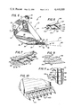
- FIG. 1 is a perspective view of a digging bucket apparatus made in accordance with the present invention
- FIG. 2 is a front elevation view of the bucket illustrated in FIG. 1 with some parts being broken away therefrom;
- FIG. 3 is a fragmentary, bottom view of the bucket disclosed in the foregoing figures with some parts thereof being removed therefrom, and some of the remaining parts being shown in cross-section;
- FIG. 4 is a fragmentary, top view of the bucket disclosed in the foregoing figures, with some parts being removed therefrom;
- FIG. 5 is a rear view of the bucket disclosed in the foregoing figures.
- FIG. 6 is a side elevational view of the bucket disclosed in the foregoing figures, with some parts being broken away therefrom, and some of the remaining parts being shown in cross-section;
- FIG. 7 is a fragmentary, part cross-sectional, perspective view of a modification of part of the apparatus disclosed in the foregoing figures;
- FIG. 8 is an isolated, perspective view of part of the apparatus disclosed in FIG. 7;
- FIG. 9 is a cross-sectional view of another modification of the apparatus disclosed in FIGS. 7 and 8;
- FIG. 10 is a broken, perspective view of another modification of the present invention.
- FIG. 11 is a fragmentary, top plan view of still another embodiment of the invention.
- FIG. 1 together with various other figures of the drawings, there is disclosed an excavating bucket 10 made in accordance with the present invention.
- the bucket is illustrated in attached relationship respective to a dipper stick such as may be associated with a backhoe machine, as indicated by the dot-dash lines at numeral 11.
- the bucket has an interior 12 into which excavated material is received during the excavating operation.
- the rear 14 of the bucket is spaced from the forward digging part of the bucket, and a plurality of digging teeth 16 form the forwardmost part of the bucket.
- the bottom 18 of the bucket is in the form of a flat, curved member which commences at the rear and curves slightly downwardly and then upwardly toward a bucket lip 20, to which the before mentioned digging teeth are mounted.
- the back 22 of the rear wall is attached to lifting means which are in the form of vertically disposed spaced ears 24 having bushings 26 and 28 associated therewith, preferably in accordance with my previously filed patent application Ser. No. 817,733, filed July 21, 1977.
- Spaced, opposed, sidewalls 30 are preferably arranged substantially parallel to one another and disposed in spaced vertical planes.
- the sidewalls are reinforced by the L-shaped or anglelike member 32.
- the angle member has one edge portion attached to the lip, a rear edge portion attached to the back, with end portion 33 terminating along the curved bottom, as best seen illustrated in FIGS. 1 and 6.
- Numeral 34 indicates the juncture between members 32 and 20.
- the upper edge portion 35 of the angle member is sharpened into a knife edge to aid in trimming and maintaining vertical walls of a ditch, for example.
- Longitudinally disposed wear members 36 extend from the lip to the rear wall of the bucket and assist in reinforcing the bottom of the bucket.
- the upper surface 38 of the bottom of the bucket is spaced from the bucket lip 20 by a plurality of web members 40.
- the web members are vertically disposed and extend longitudinally of the bucket.
- the upper and lower opposed edges of the web members tie the upper surface 38 and lip 20 together by welding 42 seen illustrated in FIG. 3.
- the web members extend into attached relationship with respect to member 44 to provide a load transfer member for a plurality of spaced-apart, tooth receiving shanks 46.
- the plurality of digging teeth 16 are comprised of two adjacent teeth 47 and 48, which are mirror images of one another.
- the teeth are arranged with the sides thereof abutting one another such that their cooperative action jointly provides a common penetrating member 50, which slopes upwardly at 52 in a rearward direction towards a shank receiving cavity formed within the rear marginal end 54 thereof.
- Each of the teeth 47 and 48 further include a secondary digging member 56 and 57 which cooperates together to provide a secondary earth-engaging member between adjacent primary members 50.
- a cavity 58 is formed within the rear marginal portion 54 of each of the teeth to enable the shank to be received in close tolerance relationship therewithin.
- the rear 60 of the tooth abuttingly engages member 44 of the bucket lip, while pins 62 form a fastener means by which the individual teeth are removably mounted to the shank and hence to the lip of the bucket.
- the forwardmost end 64 of adjacent digging teeth curves outwardly away from one another to form diagonal cutting edges 65 and 66.
- the penetrating member 64, 66 downwardly slopes towards the cutting edge of secondary members 67.
- the sloped face of 67 continues in an upward and rearward direction.
- the opposed outermost digging teeth 68 are mirror images of one another. The teeth are outwardly directed in a forward direction, thereby extending the cutting action of the tooth outwardly of each of the vertical walls 30.
- a plurality of web members 70 are interposed between the outer rear wall 22 and inner rear wall 72, with two of the web members being positioned in aligned relationship respective to the spaced ears 24, thereby transferring the tremendous load from the lifting member into each of the spaced wall members of the bucket.
- Numeral 74 indicates welding by which the web members are affixed to the spaced wall members 22 and 72.
- FIGS. 7 and 8 there is disclosed a modification of the digging teeth presented in the foregoing figures.
- the cutting edge of the bucket of FIG. 7 includes identical intermediate teeth 216 while the outermost teeth located on either side of the cutting edge are mirror images of one another.
- the bucket lip extends forwardly into an enlargement 75 which reduces or necks down at 76 and again enlarges at 144.
- the tooth includes a female, laterally extending cavity 77 which is made complementary respective to the enlargement 75, with the enlargement and cavity being similar to a tongue and groove, wherein the groove slidably receives the tongue in close tolerance relationship therewith.
- the cavity 77 similarly is provided with wall surfaces 80, 82, and 84, which are sized to receive elements 75, 76, and 78 therewithin such that the individual teeth may be assembled to the bucket lip by slidably mating the female cavity 77 with respect to the laterally extending enlargement 75, 76 in a telescoping manner.
- End portions 149 of the individual teeth abuttingly engage one another to provide the interface seen at 149'.
- the teeth cooperate together to provide a secondary cutting edge 156 rearwardly spaced from a primary member 164.
- the primary member includes sloped sides 147, 148 which downwardly slope at 148 into a cutting edge 165.
- the cutting edge forms a diagonal which intersects the cutting edge 156 of the secondary member.
- numeral 83 indicates the plane within which the forward portion of the bucket bottom lies
- numeral 85 indicates the digging angle automatically achieved when the bucket is placed such that the bottom of the teeth and the bucket bottom 20 simultaneously contact the ground.
- FIG. 10 there is disclosed the before-illustrated digging bucket having teeth 416 made in accordance with still another embodiment of this invention.
- the teeth are provided with a forwardly directed penetrating member having sloped walls 467 which terminate in cutting edges 464.
- the penetrating members rearwardly slope towards a V-shaped secondary cutting member 456.
- the intermediate teeth are identical to one another, while the two outermost teeth are mirror images of one another.
- Numeral 449 indicates the interface between adjacent teeth 416.
- the teeth may be individually fastened to a shank as suggested in FIG. 10, or alternatively the teeth may be attached to the bucket lip in the illustrated manner of FIGS. 7 and 9.
- the teeth 516 include the opposed outermost teeth 68, each of which include the illustrated primary and secondary members.
- the primary member curves outwardly away from the bucket in a forward direction, and includes the illustrated cutting edge which is placed at an angle.
- the face 57 of the secondary member slopes upward towards the fastener means 562 while the face of the primary member slopes upwardly and rearwardly.
- the centrally located teeth include a primary member 550 having opposed ground engaging faces 552 and 553 which slope towards opposed secondary members 556 and 557.
- the tooth shank 554 is secured to the bucket lip in the manner taught in either of the foregoing embodiments.
- the centrally located teeth 516 are identical to one another and cooperate with the other teeth to provide a continuous cutting edge across the entire width of the bucket.
- the excavating bucket of the present invention is attached to a digging implement, such as the dipper stick 11 of a backhoe machine.
- the flat bottom bucket has a continuous cutting edge which extends beyond the sides 30 thereof, while the edge portion 35 which forms part of the peripheral opening into the bucket is sharpened into a blade member. Accordingly, when the bucket is positioned as seen in FIG. 6, the bottom 20 and teeth 16 can be positioned respective to the ground to cause movement of the bucket in a forward direction to force the continuous, cutting edge to engage the ground at the optimum angle for forming a continuous smooth surface or excavation of minimum irregularities. Simultaneously with forming a smooth bottom of a ditch or the like, the edges 35 engage the sidewalls of the ditch and remove irregularities therefrom.
- the angle bracket 32 efficiently transfers the load between the digging teeth and the liting means.
- the boxed construction seen at 38, 40, and 44 reinforces the marginal front end of the bucket and enables tremendous power to be transferred from the dipper stick into the teeth.
- adjacent teeth are mirror images of one another and cooperate together to form a penetrating member 50 in advance of a secondary member 56.
- the teeth set forth in the embodiment of FIG. 7 may be employed.
- the tteth of FIG. 7 are easily mounted by merely telescoping the enlargement 80 within the cavity 77 and pinning the two outermost teeth. Where deemed desirable, each of the teeth may be individually pinned in the manner of FIG. 10.
- the tooth 316 is mounted to the bucket lip 244 by a complex tongue and groove arrangement which incudes spaced parallel grooves within which spaced, parallel, complementary tongues are slidably received.
- the male and female elements at 90 and 92 which constitute the tongue and groove, lock the teeth into proper position while abutting edge portions 94 and 96, respectively, transfer upward and downward loads, respectively, imposed on the tooth.
- the forwardly directed member 98 maintains the teeth in proper alignment respective to one another.
- the teeth of FIG. 9 are slidably received by the complementary configured lip or shank, with the adjacent teeth being held in abutting relationship respective to one another and to the bucket lip by pinning the outermost teeth in the before described manner.
Landscapes
- Engineering & Computer Science (AREA)
- Mining & Mineral Resources (AREA)
- Civil Engineering (AREA)
- General Engineering & Computer Science (AREA)
- Structural Engineering (AREA)
- Mechanical Engineering (AREA)
- Component Parts Of Construction Machinery (AREA)
Abstract
Description
Claims (18)
Priority Applications (1)
| Application Number | Priority Date | Filing Date | Title |
|---|---|---|---|
| US06/017,443 US4449309A (en) | 1979-03-05 | 1979-03-05 | Flat bottom bucket and digging teeth |
Applications Claiming Priority (1)
| Application Number | Priority Date | Filing Date | Title |
|---|---|---|---|
| US06/017,443 US4449309A (en) | 1979-03-05 | 1979-03-05 | Flat bottom bucket and digging teeth |
Publications (1)
| Publication Number | Publication Date |
|---|---|
| US4449309A true US4449309A (en) | 1984-05-22 |
Family
ID=21782618
Family Applications (1)
| Application Number | Title | Priority Date | Filing Date |
|---|---|---|---|
| US06/017,443 Expired - Lifetime US4449309A (en) | 1979-03-05 | 1979-03-05 | Flat bottom bucket and digging teeth |
Country Status (1)
| Country | Link |
|---|---|
| US (1) | US4449309A (en) |
Cited By (29)
| Publication number | Priority date | Publication date | Assignee | Title |
|---|---|---|---|---|
| US4609049A (en) * | 1982-04-26 | 1986-09-02 | Thomas Migdal | Rotary wheel type rock picker |
| US4835888A (en) * | 1987-05-01 | 1989-06-06 | Hemphill Charles W | Excavating tooth and holder therefor |
| US5088214A (en) * | 1991-01-17 | 1992-02-18 | Esco Corporation | Excavator wear edge |
| US5224555A (en) * | 1991-12-18 | 1993-07-06 | Bucyrus Blades, Inc. | Wear element for a scraping operation |
| US5224282A (en) * | 1992-01-21 | 1993-07-06 | Harnischfeger Corporation | Tooth assembly for a digger bucket |
| US5435084A (en) * | 1994-02-17 | 1995-07-25 | Harnischfeger Corporation | Apparatus and method for attaching a digging tooth tip |
| US5452529A (en) * | 1993-08-25 | 1995-09-26 | Harnischfeger Corporation | Retaining device |
| USD406153S (en) * | 1998-01-26 | 1999-02-23 | Holzer Richard A | Toothed scraper bar for earthmover bucket |
| US6230424B1 (en) * | 1998-12-08 | 2001-05-15 | Caterpillar Inc. | Base edge protection assembly for an implement of a work machine |
| EP1116435A1 (en) * | 2000-01-13 | 2001-07-18 | Dieter Opitz | Device for transplanting trees or bushes |
| US6363633B1 (en) | 1998-12-23 | 2002-04-02 | Diane Holzer | Excavating implement |
| US6434865B2 (en) * | 1998-12-08 | 2002-08-20 | Caterpillar Inc. | Base edge protection assembly for an implement of a work machine |
| US20030123934A1 (en) * | 2001-10-26 | 2003-07-03 | Steven Weaver | Surface working device and attachable protector |
| US20040060208A1 (en) * | 2002-07-01 | 2004-04-01 | Pennsylvania Crusher Corporation | Excavator teeth, apparatus and methods |
| US20040216334A1 (en) * | 2003-04-30 | 2004-11-04 | Esco Corporation | Wear assembly for the digging edge of an excavator |
| US20040237355A1 (en) * | 2001-11-09 | 2004-12-02 | Esco Corporation | Assembly for securing a wear member to an excavator |
| US20050229442A1 (en) * | 2004-03-30 | 2005-10-20 | Esco Corporation | Wear edge assembly |
| US20050284006A1 (en) * | 2003-04-30 | 2005-12-29 | Esco Corporation | Wear assembly for excavating digging edge |
| US20070204490A1 (en) * | 2004-03-30 | 2007-09-06 | Esco Corporation | Wear assembly |
| AU2002301629B2 (en) * | 2001-10-26 | 2008-04-24 | Sandvik Intellectual Property Ab | Surface working device and attachment |
| US20090056174A1 (en) * | 2007-08-29 | 2009-03-05 | Caterpillar Inc. | Soil slicing spade bit and machine using same |
| US20090183398A1 (en) * | 2008-01-17 | 2009-07-23 | Caterpillar Inc. | Excavator bucket top assembly |
| US20100000129A1 (en) * | 2005-11-15 | 2010-01-07 | Timothy Craig Balemi | Bucket Fabrication |
| USRE42629E1 (en) | 1995-11-06 | 2011-08-23 | Esco Corporation | Wear assembly for a digging edge of an excavator |
| US20120145421A1 (en) * | 2009-06-23 | 2012-06-14 | Betek Gmbh & Co. Kg | Soil Treating Tool |
| US20150218774A1 (en) * | 2011-05-02 | 2015-08-06 | Harnischfeger Technologies, Inc. | Straight taper dipper |
| US9404240B2 (en) | 2013-11-07 | 2016-08-02 | Caterpillar Inc. | Bucket lip protection assemblies and lip adapters for same |
| CN107743535A (en) * | 2015-06-09 | 2018-02-27 | 卡特彼勒公司 | Adjust pad for ground engagement instrument |
| US20210317631A1 (en) * | 2018-09-10 | 2021-10-14 | Komatsu Ltd. | Bucket and work vehicle |
Citations (17)
| Publication number | Priority date | Publication date | Assignee | Title |
|---|---|---|---|---|
| US802036A (en) * | 1905-06-27 | 1905-10-17 | Frederick Wm French | Cultivating implement. |
| US1197104A (en) * | 1914-12-09 | 1916-09-05 | American Manganese Steel Co | Dipper-tooth. |
| US1545621A (en) * | 1924-12-26 | 1925-07-14 | George E Turner | Dipper for excavating machines |
| US1573137A (en) * | 1926-02-16 | Tule and sod scraper | ||
| US1696924A (en) * | 1925-01-09 | 1929-01-01 | American Manganese Steel Co | Interlocked excavator teeth |
| US1796737A (en) * | 1929-05-23 | 1931-03-17 | Lesher W Van Buskirk | Dipper tooth |
| US1804756A (en) * | 1929-08-30 | 1931-05-12 | Frank A Thompson | Shovel tooth |
| US1989776A (en) * | 1933-04-14 | 1935-02-05 | Raymond S Weimer | Tooth base for excavating buckets |
| US2211786A (en) * | 1938-03-05 | 1940-08-20 | Bucyrus Erie Co | Dipper lip and associated teeth |
| GB553954A (en) * | 1941-12-12 | 1943-06-11 | Edwin Percy Richards | An improved bucket or like vessel for underwater excavation or other suitable uses |
| DE1097738B (en) * | 1956-10-23 | 1961-01-19 | Hermann Voss | Lifting and loosening device for young plants |
| US3243906A (en) * | 1963-10-14 | 1966-04-05 | Allis Chalmers Mfg Co | Excavating bucket structure |
| US3497973A (en) * | 1967-05-01 | 1970-03-03 | Caterpillar Tractor Co | Compact high strength replaceable cutting edge |
| US3775879A (en) * | 1972-07-28 | 1973-12-04 | Int Harvester Co | Bucket for earth moving machines |
| US3914885A (en) * | 1972-11-14 | 1975-10-28 | Poclain Sa | Public works machines |
| US4127952A (en) * | 1977-06-20 | 1978-12-05 | Caterpillar Tractor Co. | Replaceable adapter for an earthworking tool |
| US4133121A (en) * | 1976-08-18 | 1979-01-09 | Hemphill Charles W | Backhoe bucket adapter bushing and pin method and apparatus |
-
1979
- 1979-03-05 US US06/017,443 patent/US4449309A/en not_active Expired - Lifetime
Patent Citations (17)
| Publication number | Priority date | Publication date | Assignee | Title |
|---|---|---|---|---|
| US1573137A (en) * | 1926-02-16 | Tule and sod scraper | ||
| US802036A (en) * | 1905-06-27 | 1905-10-17 | Frederick Wm French | Cultivating implement. |
| US1197104A (en) * | 1914-12-09 | 1916-09-05 | American Manganese Steel Co | Dipper-tooth. |
| US1545621A (en) * | 1924-12-26 | 1925-07-14 | George E Turner | Dipper for excavating machines |
| US1696924A (en) * | 1925-01-09 | 1929-01-01 | American Manganese Steel Co | Interlocked excavator teeth |
| US1796737A (en) * | 1929-05-23 | 1931-03-17 | Lesher W Van Buskirk | Dipper tooth |
| US1804756A (en) * | 1929-08-30 | 1931-05-12 | Frank A Thompson | Shovel tooth |
| US1989776A (en) * | 1933-04-14 | 1935-02-05 | Raymond S Weimer | Tooth base for excavating buckets |
| US2211786A (en) * | 1938-03-05 | 1940-08-20 | Bucyrus Erie Co | Dipper lip and associated teeth |
| GB553954A (en) * | 1941-12-12 | 1943-06-11 | Edwin Percy Richards | An improved bucket or like vessel for underwater excavation or other suitable uses |
| DE1097738B (en) * | 1956-10-23 | 1961-01-19 | Hermann Voss | Lifting and loosening device for young plants |
| US3243906A (en) * | 1963-10-14 | 1966-04-05 | Allis Chalmers Mfg Co | Excavating bucket structure |
| US3497973A (en) * | 1967-05-01 | 1970-03-03 | Caterpillar Tractor Co | Compact high strength replaceable cutting edge |
| US3775879A (en) * | 1972-07-28 | 1973-12-04 | Int Harvester Co | Bucket for earth moving machines |
| US3914885A (en) * | 1972-11-14 | 1975-10-28 | Poclain Sa | Public works machines |
| US4133121A (en) * | 1976-08-18 | 1979-01-09 | Hemphill Charles W | Backhoe bucket adapter bushing and pin method and apparatus |
| US4127952A (en) * | 1977-06-20 | 1978-12-05 | Caterpillar Tractor Co. | Replaceable adapter for an earthworking tool |
Cited By (46)
| Publication number | Priority date | Publication date | Assignee | Title |
|---|---|---|---|---|
| US4609049A (en) * | 1982-04-26 | 1986-09-02 | Thomas Migdal | Rotary wheel type rock picker |
| US4835888A (en) * | 1987-05-01 | 1989-06-06 | Hemphill Charles W | Excavating tooth and holder therefor |
| US5088214A (en) * | 1991-01-17 | 1992-02-18 | Esco Corporation | Excavator wear edge |
| WO1992013145A1 (en) * | 1991-01-17 | 1992-08-06 | Esco Corporation | Excavating wear edge with resilient lock |
| US5224555A (en) * | 1991-12-18 | 1993-07-06 | Bucyrus Blades, Inc. | Wear element for a scraping operation |
| US5224282A (en) * | 1992-01-21 | 1993-07-06 | Harnischfeger Corporation | Tooth assembly for a digger bucket |
| US5452529A (en) * | 1993-08-25 | 1995-09-26 | Harnischfeger Corporation | Retaining device |
| US5435084A (en) * | 1994-02-17 | 1995-07-25 | Harnischfeger Corporation | Apparatus and method for attaching a digging tooth tip |
| USRE42629E1 (en) | 1995-11-06 | 2011-08-23 | Esco Corporation | Wear assembly for a digging edge of an excavator |
| USD406153S (en) * | 1998-01-26 | 1999-02-23 | Holzer Richard A | Toothed scraper bar for earthmover bucket |
| US6434865B2 (en) * | 1998-12-08 | 2002-08-20 | Caterpillar Inc. | Base edge protection assembly for an implement of a work machine |
| US6230424B1 (en) * | 1998-12-08 | 2001-05-15 | Caterpillar Inc. | Base edge protection assembly for an implement of a work machine |
| US6363633B1 (en) | 1998-12-23 | 2002-04-02 | Diane Holzer | Excavating implement |
| EP1116435A1 (en) * | 2000-01-13 | 2001-07-18 | Dieter Opitz | Device for transplanting trees or bushes |
| US20030123934A1 (en) * | 2001-10-26 | 2003-07-03 | Steven Weaver | Surface working device and attachable protector |
| US6799388B2 (en) * | 2001-10-26 | 2004-10-05 | Sandvik Ab | Surface working device and attachable protector |
| AU2002301629B2 (en) * | 2001-10-26 | 2008-04-24 | Sandvik Intellectual Property Ab | Surface working device and attachment |
| AU2002301629C1 (en) * | 2001-10-26 | 2009-01-29 | Sandvik Intellectual Property Ab | Surface working device and attachment |
| US7730645B2 (en) * | 2001-11-09 | 2010-06-08 | Esco Corporation | Dredge cutterhead |
| US20040237355A1 (en) * | 2001-11-09 | 2004-12-02 | Esco Corporation | Assembly for securing a wear member to an excavator |
| US20040060208A1 (en) * | 2002-07-01 | 2004-04-01 | Pennsylvania Crusher Corporation | Excavator teeth, apparatus and methods |
| US6986216B2 (en) | 2003-04-30 | 2006-01-17 | Esco Corporation | Wear assembly for the digging edge of an excavator |
| US20060010726A1 (en) * | 2003-04-30 | 2006-01-19 | Esco Corporation | Wear assembly for an excavator |
| US7080470B2 (en) | 2003-04-30 | 2006-07-25 | Esco Corporation | Wear assembly for excavator digging edge |
| US20040216334A1 (en) * | 2003-04-30 | 2004-11-04 | Esco Corporation | Wear assembly for the digging edge of an excavator |
| US7299570B2 (en) | 2003-04-30 | 2007-11-27 | Esco Corporation | Wear assembly for an excavator |
| US20050284006A1 (en) * | 2003-04-30 | 2005-12-29 | Esco Corporation | Wear assembly for excavating digging edge |
| US7451558B2 (en) | 2003-04-30 | 2008-11-18 | Esco Corporation | Wear assembly for excavating digging edge |
| US7596895B2 (en) | 2004-03-30 | 2009-10-06 | Esco Corporation | Wear assembly |
| US20070022640A1 (en) * | 2004-03-30 | 2007-02-01 | Esco Corporation | Wear edge assembly |
| US20050229442A1 (en) * | 2004-03-30 | 2005-10-20 | Esco Corporation | Wear edge assembly |
| US20070204490A1 (en) * | 2004-03-30 | 2007-09-06 | Esco Corporation | Wear assembly |
| US7793444B2 (en) | 2004-03-30 | 2010-09-14 | Esco Corporation | Wear edge assembly |
| US20100000129A1 (en) * | 2005-11-15 | 2010-01-07 | Timothy Craig Balemi | Bucket Fabrication |
| US20090056174A1 (en) * | 2007-08-29 | 2009-03-05 | Caterpillar Inc. | Soil slicing spade bit and machine using same |
| US7841112B2 (en) * | 2007-08-29 | 2010-11-30 | Caterpillar Inc | Soil slicing spade bit and machine using same |
| US8069593B2 (en) * | 2008-01-17 | 2011-12-06 | Caterpillar Inc. | Excavator bucket top assembly |
| US20090183398A1 (en) * | 2008-01-17 | 2009-07-23 | Caterpillar Inc. | Excavator bucket top assembly |
| US20120145421A1 (en) * | 2009-06-23 | 2012-06-14 | Betek Gmbh & Co. Kg | Soil Treating Tool |
| US8857531B2 (en) * | 2009-06-23 | 2014-10-14 | Betek Gmbh & Co. Kg | Soil treating tool with hardened cutting element |
| US20150218774A1 (en) * | 2011-05-02 | 2015-08-06 | Harnischfeger Technologies, Inc. | Straight taper dipper |
| US10519621B2 (en) * | 2011-05-02 | 2019-12-31 | Joy Global Surface Mining Inc | Straight taper dipper |
| US10934682B2 (en) | 2011-05-02 | 2021-03-02 | Joy Global Surface Mining Inc | Straight taper dipper |
| US9404240B2 (en) | 2013-11-07 | 2016-08-02 | Caterpillar Inc. | Bucket lip protection assemblies and lip adapters for same |
| CN107743535A (en) * | 2015-06-09 | 2018-02-27 | 卡特彼勒公司 | Adjust pad for ground engagement instrument |
| US20210317631A1 (en) * | 2018-09-10 | 2021-10-14 | Komatsu Ltd. | Bucket and work vehicle |
Similar Documents
| Publication | Publication Date | Title |
|---|---|---|
| US4449309A (en) | Flat bottom bucket and digging teeth | |
| US4037337A (en) | Excavating bucket and teeth for a backhoe | |
| US4949481A (en) | Digging tooth assembly | |
| US4038766A (en) | Excavator bucket ripper tool | |
| US5018283A (en) | Loader bucket tooth | |
| US4123861A (en) | Method of excavating earth with a bucket | |
| US4550512A (en) | Excavator bucket with detachable implements | |
| CA2059619C (en) | Dragline bucket and method of operating the same | |
| US5992062A (en) | High penetration bucket arrangement | |
| US7992329B2 (en) | Single pointed ripper bucket excavation tool | |
| US2972425A (en) | Trench hoe dipper | |
| EP0215802B1 (en) | A ripping bucket arrangement | |
| US3325926A (en) | Digger tooth and assembly for an excavating apparatus | |
| US4117611A (en) | Digging teeth for an excavating bucket | |
| US4251933A (en) | Lip and teeth in combination with a flat bottom bucket | |
| US4321762A (en) | Digging tooth apparatus for V bottom bucket | |
| US2783558A (en) | Trenching attachment for excavating buckets | |
| US4476642A (en) | Digging tooth and holder assembly | |
| US3839806A (en) | Two-piece router bit assembly | |
| CN114718146A (en) | Wear member, edge and mounting process | |
| US2416409A (en) | Trench hoe and the like | |
| US6237260B1 (en) | Dragline bucket with quick change basket feature | |
| US3798805A (en) | Adjustable scraper blade | |
| EP0195107B1 (en) | Tooth system for earth-working tools | |
| US3309801A (en) | Repointer |
Legal Events
| Date | Code | Title | Description |
|---|---|---|---|
| AS | Assignment |
Owner name: ADCO BUCKETS, INC., A CORP. OF TX Free format text: ASSIGNMENT OF ASSIGNORS INTEREST.;ASSIGNOR:HEMPHILL, CHARLES W., INDIVIDUALLY;REEL/FRAME:003866/0702 Effective date: 19810219 |
|
| STCF | Information on status: patent grant |
Free format text: PATENTED CASE |
|
| AS | Assignment |
Owner name: BANK ONE, TEXAS, N.A., TEXAS Free format text: SECURITY INTEREST;ASSIGNOR:GH HENSLEY INDUSTRIES, INC.;REEL/FRAME:007340/0340 Effective date: 19950202 |
|
| AS | Assignment |
Owner name: BANK ONE, TEXAS, N.A., TEXAS Free format text: SECURITY INTEREST;ASSIGNOR:GH HENSLEY INDUSTRIES, INC.;REEL/FRAME:008274/0922 Effective date: 19961213 |
|
| AS | Assignment |
Owner name: HENSLEY INDUSTRIES, INC., FKA G.H. HENSELY INDUSTR Free format text: RELEASE OF SECURITY AGREEMENT AND ASSIGNMENT OF PATENTS AND TRADEMARKS AND ASSIGNMENT OF PATENTS.;ASSIGNOR:BANK ONE, TEXAS, N.A.;REEL/FRAME:011648/0817 Effective date: 20001201 |