US4417618A - Air-conditioner control system for vehicles - Google Patents

Air-conditioner control system for vehicles Download PDF

Info

Publication number
US4417618A
US4417618A US06/275,508 US27550881A US4417618A US 4417618 A US4417618 A US 4417618A US 27550881 A US27550881 A US 27550881A US 4417618 A US4417618 A US 4417618A
Authority
US
United States
Prior art keywords
air
temperature
air duct
outlet
supply
Prior art date
Legal status (The legal status is an assumption and is not a legal conclusion. Google has not performed a legal analysis and makes no representation as to the accuracy of the status listed.)
Expired - Lifetime
Application number
US06/275,508
Inventor
Akiro Yoshimi
Michihiko Kamiya
Mitsutoshi Moriya
Current Assignee (The listed assignees may be inaccurate. Google has not performed a legal analysis and makes no representation or warranty as to the accuracy of the list.)
Denso Corp
Original Assignee
NipponDenso Co Ltd
Priority date (The priority date is an assumption and is not a legal conclusion. Google has not performed a legal analysis and makes no representation as to the accuracy of the date listed.)
Filing date
Publication date
Application filed by NipponDenso Co Ltd filed Critical NipponDenso Co Ltd
Assigned to NIPPONDENSO CO., LTD. reassignment NIPPONDENSO CO., LTD. ASSIGNMENT OF ASSIGNORS INTEREST. Assignors: KAMIYA, MICHIHIKO, MORIYA, MITSUTOSHI, YOSHIMI, AKIRO
Application granted granted Critical
Publication of US4417618A publication Critical patent/US4417618A/en
Anticipated expiration legal-status Critical
Expired - Lifetime legal-status Critical Current

Links

Images

Classifications

    • BPERFORMING OPERATIONS; TRANSPORTING
    • B60VEHICLES IN GENERAL
    • B60HARRANGEMENTS OF HEATING, COOLING, VENTILATING OR OTHER AIR-TREATING DEVICES SPECIALLY ADAPTED FOR PASSENGER OR GOODS SPACES OF VEHICLES
    • B60H1/00Heating, cooling or ventilating [HVAC] devices
    • B60H1/00642Control systems or circuits; Control members or indication devices for heating, cooling or ventilating devices
    • B60H1/00814Control systems or circuits characterised by their output, for controlling particular components of the heating, cooling or ventilating installation
    • B60H1/00821Control systems or circuits characterised by their output, for controlling particular components of the heating, cooling or ventilating installation the components being ventilating, air admitting or air distributing devices
    • B60H1/00835Damper doors, e.g. position control
    • B60H1/00842Damper doors, e.g. position control the system comprising a plurality of damper doors; Air distribution between several outlets
    • FMECHANICAL ENGINEERING; LIGHTING; HEATING; WEAPONS; BLASTING
    • F24HEATING; RANGES; VENTILATING
    • F24FAIR-CONDITIONING; AIR-HUMIDIFICATION; VENTILATION; USE OF AIR CURRENTS FOR SCREENING
    • F24F11/00Control or safety arrangements
    • F24F11/30Control or safety arrangements for purposes related to the operation of the system, e.g. for safety or monitoring
    • GPHYSICS
    • G05CONTROLLING; REGULATING
    • G05DSYSTEMS FOR CONTROLLING OR REGULATING NON-ELECTRIC VARIABLES
    • G05D23/00Control of temperature
    • G05D23/19Control of temperature characterised by the use of electric means
    • G05D23/1917Control of temperature characterised by the use of electric means using digital means
    • GPHYSICS
    • G05CONTROLLING; REGULATING
    • G05DSYSTEMS FOR CONTROLLING OR REGULATING NON-ELECTRIC VARIABLES
    • G05D23/00Control of temperature
    • G05D23/19Control of temperature characterised by the use of electric means
    • G05D23/20Control of temperature characterised by the use of electric means with sensing elements having variation of electric or magnetic properties with change of temperature

Definitions

  • the present invention relates to improvements in an air-conditioner control system for vehicles having a plurality of air supply outlets and designed to determine the distribution of conditioned air supplied to a vehicle compartment through the air supply outlets.
  • the object of the present invention to provide an improved air-conditioner control system so designed that when an air conditioner is in the heater supply mode of operation and a level of insolation exceeding a predetermined level is sensed, the operation mode of the air outlets is changed to a bi-level supply mode and simultaneously the conditioned air of comparatively low temperature is directed toward the upper part of the occupant's body by effecting the correction for insolation or by virtue of the specific construction of the air conditioner, thus improving the feeling on the part of the occupant.
  • the basic factors for supply mode selection may include the temperature of supply air or the displacement of a temperature adjusting member as a parameter. Further, whether the cooler unit is in operation and so on may also be included as additional requirements.
  • FIGS. 1 to 7 illustrate a preferred embodiment of the present invention in which the invention is incorporated in an automobile air conditioning system.
  • FIG. 1 shows the overall construction of the embodiment.
  • FIG. 2 is a block diagram for the electric circuitry of the control system shown in FIG. 1.
  • FIG. 3 is a flow diagram showing the processing steps of the digital computer of FIG. 2 which governs the operation of the system.
  • FIG. 4 is a characteristic diagram showing the relationship between the supply air temperature T AO and the temperature adjusting damper opening A s for explaining the step 103 in FIG. 3.
  • FIG. 5 is a characteristic diagram showing the relationship between the supply modes and the supply air temperature T AO for explaining the step 104 in FIG. 3.
  • FIG. 6 is a characteristic diagram showing the relationship between the supply air temperature T AO and the temperature adjusting damper opening A s for explaining the step 109 in FIG. 3.
  • FIG. 7 is a characteristic diagram showing the relationship between the wind rate W and the supply air temperature T AO and the present temperature T s useful for explaining the step 112 in FIG. 3.
  • FIG. 8 is a block diagram for the electric circuitry of a control system in another embodiment of the present invention.
  • cooler supply mode denotes a condition in which an outlet damper 8 which is disposed near the air supply outlets for the conditioned air from the air conditioner is at the position shown by the solid line in FIG. 1 of the accompanying drawings of the present application and consequently the conditioned air is substantially supplied only through a lower air supply outlet 1d directed to the vehicle compartment floor.
  • bi-level supply mode denotes a condition in which the outlet damper 8 is at the position shown by the broken line in FIG. 1 so that the conditioned air of comparatively high temperature is supplied through the lower air supply outlet 1d and the conditioned air of comparatively low temperature is supplied through an upper air supply outlet 1c directed to the vehicle occupant.
  • ventilation supply mode denotes a condition in which the outlet damper 8 is at the lowermost position where it closes the lower air supply outlet 1d and consequently the conditioned air is substantially supplied only through the upper air supply outlet 1c.
  • FIG. 1 showing the overall construction of the embodiment, provided upstream of an air duct 1 arranged in the front part of a compartment of a vehicle are an outside air inlet 1a for introducing the outside air and an inside air inlet 1b for recirculating the vehicle compartment inside air and the two inlets are selectively opened and closed by an inside/outside air damper 2.
  • a blower motor 3 Arranged downstream within the air duct 1 in the below-mentioned order are a blower motor 3, an evaporator 4 forming a part of the cooling cycle CC, a heater core 5 forming a part of the heating cycle HC of an engine EG and an air mixing (A/M) damper 7 for adjusting the ratio of the air passing through the heater core 5 to the air passing through its bypass passage 6.
  • A/M air mixing
  • a control unit 10 is provided for the purpose of receiving various information signals, performing various processing steps and electrically commanding the operation of the function elements designated by numerals 1 to 8 so as to perform the desired temperature control and various operation mode controls.
  • an inside air temperature sensor 21 including a heat-sensitive resistor for generating an analog voltage signal T r ' corresponding to the sensed inside air temperature in the vehicle compartment
  • an outside air temperature sensor 22 including a heat-sensitive resistor for generating an analog voltage signal T a ' corresponding to the sensed outside air temperature
  • temperature setting means 23 including a potentiometer for generating an analog voltage signal T s ' corresponding to a preset temperature
  • an opening sensor 24 including a potentiometer for generating an analog voltage signal A s ' corresponding to the sensed opening of the air mixing damper 7
  • an insolation sensor 25 including a phototransistor for generating an analog voltage signal T sun ' corresponding to the sensed heat radiation of the sun light incident to the vehicle compartment
  • a cooled air temperature sensor 26 including a heat-sensitive resistor for generating an analog voltage signal T E ' corresponding to the sensed temperature of the cooled air downstream of the evaporator 4, a water temperature sensor
  • an electromagnetic clutch 31 for switching on and off the driving force from the engine EG to the cooling cycle CC
  • an electromagnetic valve 32 for opening and closing the cooling water recirculation path to the heater core 5 in the heating cycle HC
  • electromagnetic valve controlled vacuum actuators 33, 34 and 35 responsive to the engine negative pressure to apply the opening/closing drive force to the inside/outside air damper 2, the air mixing damper 7 and the outlet damper 8.
  • the purpose of a display panel 12 is to indicate the operating condition of the air conditioner in response to the output signal of the control unit 10.
  • control unit 10 When a vehicle ignition switch 13 is closed, the control unit 10 is supplied with electric power from a vehicle battery 14 and the control unit 10 is placed in condition for operation.
  • the control unit 10 comprises a digital computer or microcomputer 10a for performing the required information processing in accordance with a predetermined control program, an analog input interface 10b in which the analog voltage signals from the signal input means 21, 22, 23, 24 and 25 are selectively subjected to analog-to-digital conversion and applied to the computer 10a, a digital input interface 10c in which the switch on/off condition signals from the switch panel 11 are reshaped and applied to the computer 10a, an amplifier circuit 10d for amplifying the operation command signals generated from the computer 10a to be supplied to the function elements 31 to 35, a digital-analog converter circuit 10e in which the digital value generated from the computer 10a to indicate the desired rotational speed of the blower motor 3 is converted to a DC voltage for operating the blower motor 3, an information processing clock generating circuit 10f, a voltage regulator circuit (not shown), a display panel 12 for indicating the operating condition of the air conditioner, and a starting circuit (not shown) for initiating the operation of the computer 10a just after the closing of the ignition
  • FIG. 3 shows the flow of the computing steps of the control program for the computer 10a and the operation of the system will now be described with reference to FIG. 3.
  • the computer 10a When the ignition switch 13 is closed, the computer 10a is started and thereafter the computer 10a repeatedly checks through the interface 10c whether the air conditioner operating switch in the switch panel 11 is on.
  • a start step 100 causes the computer 10a to start the processing which will be described hereunder.
  • an initialization step 101 sets the internal conditions of the computer 10a and the operating condition of the air conditioner to their initial conditions. This step energizes the electromagnetic clutch 31 and the electromagnetic valve 32 via the amplifier circuit 10d and thereby initiates the operation of heat exchange in the heat exchangers 4 and 5.
  • the analog voltage signals T r ', T a ', T s ', A s ', T sun ', T E ' and T w ' respectively generated from the signal input means 21, 22, 23, 24, 25, 26 and 27 are successively received as digital data T r , T a , T s , A s , T sun , T E and T w via the interface 10b and the operating conditions of the operation mode switches in the switch panel 11 are received via the interface 10c.
  • the computing method may be to use a predetermined expression approximating the supply air temperature T AO versus air mixing damper opening A s characteristic of FIG. 4 which was preliminarily obtained by experiments or to preliminarily memorize the characteristic in the form of a memory map.
  • symbol T w indicates the heated water temperature (by the sensor 27), T E the cooled air temperature (by the sensor 26), and K E a constant term.
  • the next step 104 selects the proper supply mode corresponding to the computed supply air temperature T AO . This selection is effected by determining which of the regions defined by 25 ⁇ 1° C. and 30 ⁇ 1° C. as shown in FIG. 5 corresponds to the computed supply air temperature T AO .
  • the next steps 105 to 111 are such that if the supply mode selected by the step 104 is the ventilation supply mode, a command is applied (by the step 106) to the actuator 35 to open the upper outlet 1c. If the bi-level supply mode is selected, a command is applied (by the step 110) such that the conditioned air is supplied in a bi-level manner or the damper 8 is placed in the intermediate position shown by the broken line. In the event that the heater supply mode is selected, if there is no insolation, a heater supply mode command is applied (by the step 111). If there is detected the presence of insolation of a level higher than a predetermined level, in accordance with the bi-level supply temperature characteristic (see FIG.
  • the step 109 determines whether a condition that a ventilation supply air temperature T AOV is less than 30° C. (namely, a supply air temperature T AO is less than a predetermined value T A ) is satisfied. If T AO ⁇ T A , the supply mode is changed to the bi-level supply mode (by the step 110). If the ventilation supply air temperature T AOV is equal to or higher than 30° C., that signifies T AO ⁇ T A , the heater supply mode is maintained (by the step 111). In this connection, FIG. 6 shows a condition where in the bi-level supply air mode the heater supply temperature T AOH differs in value from the ventilation supply air temperature T AOV .
  • the arrangement of the air mixing damper 7, the heater core 5, etc., in the air conditioner unit may be suitably preset or alternatively a known construction may for example be used in which a special auxiliary duct leads from the downstream portion of the evaporator 4 to the upper outlet 1c to bypass the air mixing damper 7 and the heater core 5 so that the valve in the auxiliary duct is opened interlinked with the outlet damper 8 in the bi-level supply mode.
  • the supply air temperature T AO is determined such that the vehicle compartment temperature T r is brought near to and maintained at the preset desired temperature T s , and the opening A s of the air mixing damper 7 is adjusted accordingly.
  • the heater supply mode, the ventilation supply mode or the bi-level supply mode is selected.
  • the bi-level supply mode is selected automatically so far as the ventilation supply air temperature T AOV from the upper outlet (the ventilation outlet) remains lower than a predetermined temperature of 30° C., for example.
  • the system prevents the high-temperature heated air from being blown toward the upper part of the occupant's body.
  • a step 112 performs the computation of a wind rate W from the supply air temperature T AO on the basis of the characteristic shown in FIG. 7.
  • a step 113 controls the actuator 34 so as to attain the opening A so of the air mixing damper 7 which was computed by the step 103, thus causing the opening A s of the air mixing damper 7 to become the opening A so for performing the temperature adjustment.
  • a step 114 applies a digital value to the digital-analog converter circuit 10e so as to supply to the blower motor 3 an applied voltage corresponding to the wind rate W computed by the step 112.
  • FIG. 8 shows another embodiment for this purpose.
  • numeral 40 designates a known type of control circuit comprising an operational amplifier or the like, and a temperature setting variable resistor 41, an inside air temperature sensor 42, an outside air temperature sensor 43 and a feedback potentiometer 44 associated with the air mixing damper are connected in series as input resistors for the control circuit 40.
  • the known type of control circuit 40 applies to an actuating unit 48 a signal corresponding to the difference between the preset value of the temperature setting resistor 41 and the combined resistance of the other resistors 42 to 44 and the actuating unit 48 actuates a controller 51 adapted to adjust for example the opening of the air mixing damper, thus performing the temperature adjustment so as to reduce the difference to zero.
  • Numeral 49 designates a voltage regulator circuit, and 50 an operating switch which is closed to bring the blower motor 3, the actuating unit 48, etc., into operation.
  • Numeral 52 designates an outlet change-over circuit responsive to the output of the control circuit 40 so as to operate electromagnetic valves 46 and 47 forming the actuator 35 and change the position of the outlet damper.
  • An insolation sensor 45 comprising a photodiode senses the intensity of insolation so that if there is insolation and a condition of greater than 300 Kcal/m 2 of insolation is sensed, the electromagnetic valves 46 and 47 are automatically energized to change the supply mode to the bi-level supply mode and thereby to maintain the damper opening detected by the potentiometer 44a below a predetermined value (i.e., the ventilation outlet temperature is maintained lower than 30° C. in the bi-level supply mode).
  • the present invention may be embodied in a system which includes no automatic supply mode change-over mechanism and which simply indicates a suitable supply mode to the occupants by means of a display or other alarming device.
  • the presence of insolation is used as a condition for supply mode change-over, thus preventing the deterioration of feeling due to insolation during the heater supply mode of operation and thereby ensuring a feeling of comfortable air conditioning on the part of the occupants.

Abstract

An air-conditioner control system for vehicles which is responsive to a condition in the compartment of a vehicle to move an air-flow controlling damper in an air duct. When the supply mode of conditioned air is a heater supply mode and when it is detected that the level of insolation in the vehicle compartment is higher than a predetermined level, the control system alters the supply mode of conditioned air to a bi-level supply mode.

Description

BACKGROUND OF THE INVENTION
1. Field of the Invention
The present invention relates to improvements in an air-conditioner control system for vehicles having a plurality of air supply outlets and designed to determine the distribution of conditioned air supplied to a vehicle compartment through the air supply outlets.
2. Description of the Prior Art
It is well known in the art to vary the distribution of air blown into the upper and lower portions of a compartment of a vehicle. For instance, disclosed in Japanese Laid-Open Patent Application Publication No. 55-47914 is a system in which in accordance with the temperature of air to be supplied to the vehicle compartment, the cooled air is chiefly blown into the upper portion of the compartment and the heated air is chiefly blown into the lower portion of the compartment. Also, a similar system is disclosed in Japanese Utility Model Publication No. 54-12819. Thus, in these known systems the heated air is chiefly blown into the lower portion of the vehicle compartment in winter. However, there is a disadvantage that if the occupant is exposed to the heat radiation of the sunlight incident to the vehicle compartment during the heater supply mode of operation, mainly the upper part of the body is exposed to the heat radiation. Sometimes the occupant has a sensation of excessive heating in the upper part of the body and the air supplied from the air conditioner practically fails to reach the upper part of the body, thus failing to lessen the sensation of the excessive heating and thereby deteriorating the feeling on the part of the occupant.
In this connection, air-conditioning systems of the type incorporating an automatic temperature adjusting unit for correcting the supply air temperature in accordance with the intensity of solar radiation or insolation are known in the art (Japanese Utility Model Publication No. 49-6021, etc.), and in accordance with this correction the supply air temperature is decreased in accordance with the degree of insolation with the result that during the above-mentioned heater supply mode of operation the temperature of the air supplied toward the lower part of the occupant's body is decreased causing the occupant to feel cold and this, coupled with a sensation of heating in the upper part of the body, aggravates the feeling on the part of the occupant.
In connection with the air-conditioner control systems stated in Japanese Utility Model Publications No. 54-31468 and No. 54-31469, there is disclosed the method of cancelling or reducing the insolation correction during the heater supply mode of operation with a view to overcoming the foregoing deficiencies due to the insolation correction.
However, this method is also incapable of improving the feeling in the upper part of the occupant's body.
SUMMARY OF THE INVENTION
With a view to overcoming the foregoing deficiencies in the prior art, it is the object of the present invention to provide an improved air-conditioner control system so designed that when an air conditioner is in the heater supply mode of operation and a level of insolation exceeding a predetermined level is sensed, the operation mode of the air outlets is changed to a bi-level supply mode and simultaneously the conditioned air of comparatively low temperature is directed toward the upper part of the occupant's body by effecting the correction for insolation or by virtue of the specific construction of the air conditioner, thus improving the feeling on the part of the occupant.
In the actual application, the basic factors for supply mode selection may include the temperature of supply air or the displacement of a temperature adjusting member as a parameter. Further, whether the cooler unit is in operation and so on may also be included as additional requirements.
BRIEF DESCRIPTION OF THE DRAWING
FIGS. 1 to 7 illustrate a preferred embodiment of the present invention in which the invention is incorporated in an automobile air conditioning system.
FIG. 1 shows the overall construction of the embodiment.
FIG. 2 is a block diagram for the electric circuitry of the control system shown in FIG. 1.
FIG. 3 is a flow diagram showing the processing steps of the digital computer of FIG. 2 which governs the operation of the system.
FIG. 4 is a characteristic diagram showing the relationship between the supply air temperature TAO and the temperature adjusting damper opening As for explaining the step 103 in FIG. 3.
FIG. 5 is a characteristic diagram showing the relationship between the supply modes and the supply air temperature TAO for explaining the step 104 in FIG. 3.
FIG. 6 is a characteristic diagram showing the relationship between the supply air temperature TAO and the temperature adjusting damper opening As for explaining the step 109 in FIG. 3.
FIG. 7 is a characteristic diagram showing the relationship between the wind rate W and the supply air temperature TAO and the present temperature Ts useful for explaining the step 112 in FIG. 3.
FIG. 8 is a block diagram for the electric circuitry of a control system in another embodiment of the present invention.
DESCRIPTION OF THE PREFERRED EMBODIMENTS
The present invention will now be described in greater detail with reference to the ilustrated embodiments.
The definitions of the technical terms used in connection with the control operation of the air-conditioner control system for vehicles in accordance with the present invention will be described first.
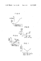
The term "heater supply mode" denotes a condition in which an outlet damper 8 which is disposed near the air supply outlets for the conditioned air from the air conditioner is at the position shown by the solid line in FIG. 1 of the accompanying drawings of the present application and consequently the conditioned air is substantially supplied only through a lower air supply outlet 1d directed to the vehicle compartment floor.
The term "bi-level supply mode" denotes a condition in which the outlet damper 8 is at the position shown by the broken line in FIG. 1 so that the conditioned air of comparatively high temperature is supplied through the lower air supply outlet 1d and the conditioned air of comparatively low temperature is supplied through an upper air supply outlet 1c directed to the vehicle occupant.
The term "ventilation supply mode" denotes a condition in which the outlet damper 8 is at the lowermost position where it closes the lower air supply outlet 1d and consequently the conditioned air is substantially supplied only through the upper air supply outlet 1c.
In the embodiment which will now be described, the present invention is incorporated in an automobile air conditioning system of the conventional cooled and heated air mixing type. In FIG. 1 showing the overall construction of the embodiment, provided upstream of an air duct 1 arranged in the front part of a compartment of a vehicle are an outside air inlet 1a for introducing the outside air and an inside air inlet 1b for recirculating the vehicle compartment inside air and the two inlets are selectively opened and closed by an inside/outside air damper 2. Arranged downstream within the air duct 1 in the below-mentioned order are a blower motor 3, an evaporator 4 forming a part of the cooling cycle CC, a heater core 5 forming a part of the heating cycle HC of an engine EG and an air mixing (A/M) damper 7 for adjusting the ratio of the air passing through the heater core 5 to the air passing through its bypass passage 6. Provided in the downstream-most portion of the air duct 1 are the upper and lower air supply outlets 1c and 1d for respectively blowing the air conditioned in the duct 1 into the upper and lower portions of the vehicle compartment and the two outlets are opened and closed by the outlet damper 8.
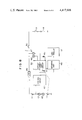
A control unit 10 is provided for the purpose of receiving various information signals, performing various processing steps and electrically commanding the operation of the function elements designated by numerals 1 to 8 so as to perform the desired temperature control and various operation mode controls.
Provided as means of supplying various information signals to the control unit 10 are an inside air temperature sensor 21 including a heat-sensitive resistor for generating an analog voltage signal Tr ' corresponding to the sensed inside air temperature in the vehicle compartment, an outside air temperature sensor 22 including a heat-sensitive resistor for generating an analog voltage signal Ta ' corresponding to the sensed outside air temperature, temperature setting means 23 including a potentiometer for generating an analog voltage signal Ts ' corresponding to a preset temperature, an opening sensor 24 including a potentiometer for generating an analog voltage signal As ' corresponding to the sensed opening of the air mixing damper 7, an insolation sensor 25 including a phototransistor for generating an analog voltage signal Tsun ' corresponding to the sensed heat radiation of the sun light incident to the vehicle compartment, a cooled air temperature sensor 26 including a heat-sensitive resistor for generating an analog voltage signal TE ' corresponding to the sensed temperature of the cooled air downstream of the evaporator 4, a water temperature sensor 27 including a heat-sensitive resistor for generating an analog voltage signal Tw ' corresponding to the sensed temperature of the heated water flowing through the heater core 5, and a switch panel 11 for generating on/off condition signals in response to the operations of a group of switches, such as, start, stop and operation mode switches.
As provided as means responsive to the electric commands from the control units 10 to operate the function elements are an electromagnetic clutch 31 for switching on and off the driving force from the engine EG to the cooling cycle CC, an electromagnetic valve 32 for opening and closing the cooling water recirculation path to the heater core 5 in the heating cycle HC and electromagnetic valve controlled vacuum actuators 33, 34 and 35 responsive to the engine negative pressure to apply the opening/closing drive force to the inside/outside air damper 2, the air mixing damper 7 and the outlet damper 8. The purpose of a display panel 12 is to indicate the operating condition of the air conditioner in response to the output signal of the control unit 10.
When a vehicle ignition switch 13 is closed, the control unit 10 is supplied with electric power from a vehicle battery 14 and the control unit 10 is placed in condition for operation.
As shown in FIG. 2, the control unit 10 comprises a digital computer or microcomputer 10a for performing the required information processing in accordance with a predetermined control program, an analog input interface 10b in which the analog voltage signals from the signal input means 21, 22, 23, 24 and 25 are selectively subjected to analog-to-digital conversion and applied to the computer 10a, a digital input interface 10c in which the switch on/off condition signals from the switch panel 11 are reshaped and applied to the computer 10a, an amplifier circuit 10d for amplifying the operation command signals generated from the computer 10a to be supplied to the function elements 31 to 35, a digital-analog converter circuit 10e in which the digital value generated from the computer 10a to indicate the desired rotational speed of the blower motor 3 is converted to a DC voltage for operating the blower motor 3, an information processing clock generating circuit 10f, a voltage regulator circuit (not shown), a display panel 12 for indicating the operating condition of the air conditioner, and a starting circuit (not shown) for initiating the operation of the computer 10a just after the closing of the ignition switch 13.
FIG. 3 shows the flow of the computing steps of the control program for the computer 10a and the operation of the system will now be described with reference to FIG. 3.
When the ignition switch 13 is closed, the computer 10a is started and thereafter the computer 10a repeatedly checks through the interface 10c whether the air conditioner operating switch in the switch panel 11 is on.
When the operating switch in the switch panel 11 is closed, a start step 100 causes the computer 10a to start the processing which will be described hereunder. Firstly, an initialization step 101 sets the internal conditions of the computer 10a and the operating condition of the air conditioner to their initial conditions. This step energizes the electromagnetic clutch 31 and the electromagnetic valve 32 via the amplifier circuit 10d and thereby initiates the operation of heat exchange in the heat exchangers 4 and 5. By the next data input step 102 the analog voltage signals Tr ', Ta ', Ts ', As ', Tsun ', TE ' and Tw ' respectively generated from the signal input means 21, 22, 23, 24, 25, 26 and 27 are successively received as digital data Tr, Ta, Ts, As, Tsun, TE and Tw via the interface 10b and the operating conditions of the operation mode switches in the switch panel 11 are received via the interface 10c.
In the next step 103 the supply air temperature TAO required for attaining the preset temperature is computed from the following preliminarily programmed expression
T.sub.AO =K.sub.s ·T.sub.s -K.sub.r ·T.sub.r -K.sub.a ·T.sub.a -K.sub.sun ·T.sub.sun +C
where Ks, Kr, Ka, Ksun and C are preset constant terms. Then the required opening Aso of the air mixing damper 7 for attaining the computed supply air temperature TAO is computed. The computing method may be to use a predetermined expression approximating the supply air temperature TAO versus air mixing damper opening As characteristic of FIG. 4 which was preliminarily obtained by experiments or to preliminarily memorize the characteristic in the form of a memory map. In FIG. 4, symbol Tw indicates the heated water temperature (by the sensor 27), TE the cooled air temperature (by the sensor 26), and KE a constant term.
The next step 104 selects the proper supply mode corresponding to the computed supply air temperature TAO. This selection is effected by determining which of the regions defined by 25±1° C. and 30±1° C. as shown in FIG. 5 corresponds to the computed supply air temperature TAO.
The next steps 105 to 111 are such that if the supply mode selected by the step 104 is the ventilation supply mode, a command is applied (by the step 106) to the actuator 35 to open the upper outlet 1c. If the bi-level supply mode is selected, a command is applied (by the step 110) such that the conditioned air is supplied in a bi-level manner or the damper 8 is placed in the intermediate position shown by the broken line. In the event that the heater supply mode is selected, if there is no insolation, a heater supply mode command is applied (by the step 111). If there is detected the presence of insolation of a level higher than a predetermined level, in accordance with the bi-level supply temperature characteristic (see FIG. 6) the step 109 determines whether a condition that a ventilation supply air temperature TAOV is less than 30° C. (namely, a supply air temperature TAO is less than a predetermined value TA) is satisfied. If TAO <TA, the supply mode is changed to the bi-level supply mode (by the step 110). If the ventilation supply air temperature TAOV is equal to or higher than 30° C., that signifies TAO ≧TA, the heater supply mode is maintained (by the step 111). In this connection, FIG. 6 shows a condition where in the bi-level supply air mode the heater supply temperature TAOH differs in value from the ventilation supply air temperature TAOV. For the purpose of obtaining such a characteristic, the arrangement of the air mixing damper 7, the heater core 5, etc., in the air conditioner unit may be suitably preset or alternatively a known construction may for example be used in which a special auxiliary duct leads from the downstream portion of the evaporator 4 to the upper outlet 1c to bypass the air mixing damper 7 and the heater core 5 so that the valve in the auxiliary duct is opened interlinked with the outlet damper 8 in the bi-level supply mode.
Thus, by the action of the system the supply air temperature TAO is determined such that the vehicle compartment temperature Tr is brought near to and maintained at the preset desired temperature Ts, and the opening As of the air mixing damper 7 is adjusted accordingly. In accordance with the thus determined supply air temperature TAO, the heater supply mode, the ventilation supply mode or the bi-level supply mode is selected. In the event that the heater supply mode has been selected, if the detected level of insolation is greater than a predetermined value, the bi-level supply mode is selected automatically so far as the ventilation supply air temperature TAOV from the upper outlet (the ventilation outlet) remains lower than a predetermined temperature of 30° C., for example.
In this way, it is possible to eliminate any sensation of excessive heating in the upper part of the occupant's body exposed to the heat radiation of the sun light while blowing the heated air toward the lower part of the occupant's body. In addition, the system prevents the high-temperature heated air from being blown toward the upper part of the occupant's body.
Then, in accordance with a predetermined relationship or memory map, a step 112 performs the computation of a wind rate W from the supply air temperature TAO on the basis of the characteristic shown in FIG. 7.
A step 113 controls the actuator 34 so as to attain the opening Aso of the air mixing damper 7 which was computed by the step 103, thus causing the opening As of the air mixing damper 7 to become the opening Aso for performing the temperature adjustment. Then, a step 114 applies a digital value to the digital-analog converter circuit 10e so as to supply to the blower motor 3 an applied voltage corresponding to the wind rate W computed by the step 112.
The above-described computational operations by the steps 102 to 114 are performed repeatedly at a period which is usually sufficiently short and which is determined by the operating clock frequency of the computer 10a. Immediately when the stop switch in the switch panel 11 is closed or the ignition switch 13 is opened during the execution of these computational operations, all the processing of FIG. 3 is stopped and the computer 10a and the air conditioner are restored to their conditions before the initialization by the step 101.
The control of the inside/outside air damper 2 and the control of the electromagnetic clutch 31 and the electromagnetic valve 32 will not be explained since they have no bearing on the subject matter of the present invention.
While, in the above-described embodiment, the digital computer is used, it may be replaced with analog circuitry.
FIG. 8 shows another embodiment for this purpose. In the Figure, numeral 40 designates a known type of control circuit comprising an operational amplifier or the like, and a temperature setting variable resistor 41, an inside air temperature sensor 42, an outside air temperature sensor 43 and a feedback potentiometer 44 associated with the air mixing damper are connected in series as input resistors for the control circuit 40. The known type of control circuit 40 applies to an actuating unit 48 a signal corresponding to the difference between the preset value of the temperature setting resistor 41 and the combined resistance of the other resistors 42 to 44 and the actuating unit 48 actuates a controller 51 adapted to adjust for example the opening of the air mixing damper, thus performing the temperature adjustment so as to reduce the difference to zero. Numeral 49 designates a voltage regulator circuit, and 50 an operating switch which is closed to bring the blower motor 3, the actuating unit 48, etc., into operation.
Numeral 52 designates an outlet change-over circuit responsive to the output of the control circuit 40 so as to operate electromagnetic valves 46 and 47 forming the actuator 35 and change the position of the outlet damper. An insolation sensor 45 comprising a photodiode senses the intensity of insolation so that if there is insolation and a condition of greater than 300 Kcal/m2 of insolation is sensed, the electromagnetic valves 46 and 47 are automatically energized to change the supply mode to the bi-level supply mode and thereby to maintain the damper opening detected by the potentiometer 44a below a predetermined value (i.e., the ventilation outlet temperature is maintained lower than 30° C. in the bi-level supply mode).
In addition, the present invention may be embodied in a system which includes no automatic supply mode change-over mechanism and which simply indicates a suitable supply mode to the occupants by means of a display or other alarming device.
It will thus be seen from the foregoing that in accordance with the present invention, the presence of insolation is used as a condition for supply mode change-over, thus preventing the deterioration of feeling due to insolation during the heater supply mode of operation and thereby ensuring a feeling of comfortable air conditioning on the part of the occupants.

Claims (6)

We claim:
1. An air conditioning system for a vehicle compartment of an automotive vehicle comprising:
an air duct having an inlet for receiving air to be conditioned and a first and a second outlets for supplying conditioned air into the vehicle compartment, said first and second outlets being directed to an upper and a lower portion of the vehicle compartment, respectively;
an air conditioner for cooling and heating air received through said inlet of said air duct to supply conditioned air through said first and second outlets of said air duct;
an air distributing damper positioned in said air duct downstream of and in cascade with said air conditioner to be movable to a first, second and third positions, said damper substantially closing said second outlet of said air duct at said first position thereof to supply conditioned air of a comparatively low temperature through said first outlet of said air duct, said damper substantially closing said first outlet of said air duct at said second position thereof to supply conditioned air of a comparatively high temperature through said second outlet of said air duct, and said damper further permitting, at said third position thereof, said first and second outlets of said air duct to supply conditioned air of comparatively low and high temperatures through said first and second outlets of said air duct, respectively;
first means for setting a desired temperature in the vehicle compartment;
second means sensing an actual temperature in the vehicle compartment;
third means sensing an insolation level in the vehicle compartment;
first control means controlling the rate of cooling and heating of said air conditioner to effect a temperature of the conditioned air on the basis of the desired temperature along with other conditional temperature information including an output signal of said third means; and
second control means controlling the position of said air distributing damper in relation to the controlled rate of cooling and heating of said air conditioner, said second control means controlling said air distributing damper to move from said second position to said third position when insolation of a level higher than a predetermined level in the vehicle compartment is sensed by said third means and said air distributing damper is at said second position thereof.
2. A system according to claim 1, wherein the controlling of said second control means is effected upon determination that the temperature of the conditioned air is lower than a predetermined temperature.
3. A system according to claim 1, wherein said air conditioner comprises an evaporator, a heater core, a bypass passage and an air mixing damper, and, when said air distributing damper is at said third position thereof, said first outlet of said air duct communicates with said bypass passage and said second outlet of said air duct communicates with said heater core, and the temperature of conditioned air supplied through said first outlet of said air duct is lower than the temperature of conditioned air supplied through said second outlet of said air duct.
4. An air conditioning system for a vehicle compartment of an automotive vehicle comprising:
an air ducting having an inlet for receiving air to be conditioned and a first and a second outlets for supplying conditioned air into the vehicle compartment, said first and second outlets being directed to an upper and a lower portion of the vehicle compartment, respectively;
an air conditioner for cooling and heating air received through said inlet of said air duct to supply conditioned air through said first and second outlets of said air duct;
an air distributing damper positioned in said air duct downstream of and in cascade with said air conditioner to be movable to a first, second and third positions, said damper substantially closing said second outlet of said air duct at said first position thereof to supply conditioned air of a comparatively low temperature through said first outlet of said air duct, said damper substantially closing said first outlet of said air duct at said second position thereof to supply conditioned air of a comparatively high temperature through said second outlet of said air duct, and said damper further permitting, at said third position thereof, said first and second outlets of said air duct to supply conditioned air of comparatively low and high temperatures through said first and second outlets of said air duct, respectively;
first means for setting a desired temperature in the vehicle compartment;
second means sensing an actual temperature in the vehicle compartment;
third means sensing an insolation level in the vehicle compartment; and a microcomputer and input/output means thereof functioning so that, when a temperature of conditioned air supplied through said air supply outlets has been computed and the supply mode has been selected to be a heater supply mode in accordance with the computed supply air temperature, an alteration from the heater supply mode to the bi-level supply mode is effected upon detection that the level of insolation in said vehicle compartment is higher than the predetermined level and upon determination that the computed supply air temperature is lower than a predetermined temperature.
5. A system according to claim 4, wherein said microcomputer has another function of generating command signals for the adjustment of a wind rate and a temperature of conditioned air supplied through said air supply outlets.
6. A system according to claim 4, wherein said air conditioner comprises an evaporator, a heater core, a bypass passage and an air mixing damper, and, when said air distributing damper is at said third position thereof, said first outlet of said air duct communicates with said bypass passage and said second outlet of said air duct communicates with said heater core, and the temperature of conditioned air supplied through said first outlet of said air duct is lower than the temperature of conditioned air supplied through said second outlet of said air duct.
US06/275,508 1980-06-27 1981-06-19 Air-conditioner control system for vehicles Expired - Lifetime US4417618A (en)

Applications Claiming Priority (2)

Application Number Priority Date Filing Date Title
JP55-88412 1980-06-27
JP55088412A JPS6021887B2 (en) 1980-06-27 1980-06-27 Vehicle air conditioning control device

Publications (1)

Publication Number Publication Date
US4417618A true US4417618A (en) 1983-11-29

Family

ID=13942075

Family Applications (1)

Application Number Title Priority Date Filing Date
US06/275,508 Expired - Lifetime US4417618A (en) 1980-06-27 1981-06-19 Air-conditioner control system for vehicles

Country Status (2)

Country Link
US (1) US4417618A (en)
JP (1) JPS6021887B2 (en)

Cited By (18)

* Cited by examiner, † Cited by third party
Publication number Priority date Publication date Assignee Title
US4566528A (en) * 1983-05-03 1986-01-28 Suddeutsche Kuhlerfabrik Julius Fr. Behr Gmbh & Co Kg Regulator circuit for vehicle air conditioner
US4602675A (en) * 1982-09-10 1986-07-29 Nissan Shatai Company, Limited Air conditioner for automotive vehicle or the like
EP0219324A2 (en) * 1985-10-11 1987-04-22 Sanden Corporation Air distribution mechanism for an automotive air conditioning system
US4690203A (en) * 1985-03-18 1987-09-01 Diesel Kiki Kabushiki Kaisha Automotive air-conditioning system adapted to obviate the influence of insolation during blower start-up
FR2618386A1 (en) * 1987-07-23 1989-01-27 Bosch Gmbh Robert AIR CONDITIONING INSTALLATION
US4819715A (en) * 1983-09-14 1989-04-11 Nissan Shatai Company, Limited Automatic air conditioning system for an automotive vehicle
US4856710A (en) * 1982-11-05 1989-08-15 Nissan Motor Company, Limited Dual air conditioner for a vehicle
US4865119A (en) * 1986-02-04 1989-09-12 Hitachi, Ltd. Air conditioner system for automotive vehicles
US4949624A (en) * 1988-12-15 1990-08-21 Nissan Motor Co. Ltd. Air conditioning system for use with automotive vehicle
FR2697476A1 (en) * 1992-10-30 1994-05-06 Renault Control system for air conditioning unit of motor vehicle - uses electronic control of division of air flow from circulation fan between cabin and engine cooling system
US5626186A (en) * 1994-03-17 1997-05-06 Nippondenso Co., Ltd. Air conditioning apparatus for vehicles
US5971066A (en) * 1998-02-27 1999-10-26 Ford Motor Company System and method for prevention of windshield fogging in a motor vehicle
US6186883B1 (en) 1998-05-28 2001-02-13 Rover Group Limited Climate control arrangement and a method of controlling that arrangement
US20040016250A1 (en) * 2001-07-24 2004-01-29 Nobuya Nakagawa Vehicle air-conditioning system
US6962196B2 (en) 2002-06-06 2005-11-08 Honda Giken Kogyo Kabushiki Kaisha Mode switching control device of vehicle air-conditioning apparatus
US20070039340A1 (en) * 2003-09-03 2007-02-22 Halla Climate Control Corporation Controlling method of air conditioning system for vehicles
US20080283215A1 (en) * 2007-05-16 2008-11-20 Honda Motor Co., Ltd. Vehicle air conditioning device
US20140158784A1 (en) * 2012-12-11 2014-06-12 V2 Plug-In Hybrid Vehicle Partnership Handelsbolag Running a phev in ev mode under cold conditions

Families Citing this family (2)

* Cited by examiner, † Cited by third party
Publication number Priority date Publication date Assignee Title
JPS57186511A (en) * 1981-05-08 1982-11-17 Mitsubishi Heavy Ind Ltd Air-conditioning device for automobile
JPS5862924U (en) * 1981-10-23 1983-04-27 株式会社泉精器製作所 hair brush

Citations (5)

* Cited by examiner, † Cited by third party
Publication number Priority date Publication date Assignee Title
US3934642A (en) * 1973-04-13 1976-01-27 Rolls-Royce Motors Limited Vehicle air conditioning system
US4271897A (en) * 1977-06-29 1981-06-09 Mitsubishi Jidosha Kogyo Kabushiki Kaisha Air conditioning display system for vehicles
US4316251A (en) * 1978-10-02 1982-02-16 Nippondenso Co., Ltd. Electric control method for automobile air conditioner
US4337821A (en) * 1978-11-28 1982-07-06 Nippondenso Co., Ltd. Air conditioner system for automobiles
US4358050A (en) * 1979-06-22 1982-11-09 Nippondenso Co., Ltd. Air conditioner control method and apparatus

Patent Citations (5)

* Cited by examiner, † Cited by third party
Publication number Priority date Publication date Assignee Title
US3934642A (en) * 1973-04-13 1976-01-27 Rolls-Royce Motors Limited Vehicle air conditioning system
US4271897A (en) * 1977-06-29 1981-06-09 Mitsubishi Jidosha Kogyo Kabushiki Kaisha Air conditioning display system for vehicles
US4316251A (en) * 1978-10-02 1982-02-16 Nippondenso Co., Ltd. Electric control method for automobile air conditioner
US4337821A (en) * 1978-11-28 1982-07-06 Nippondenso Co., Ltd. Air conditioner system for automobiles
US4358050A (en) * 1979-06-22 1982-11-09 Nippondenso Co., Ltd. Air conditioner control method and apparatus

Cited By (22)

* Cited by examiner, † Cited by third party
Publication number Priority date Publication date Assignee Title
US4602675A (en) * 1982-09-10 1986-07-29 Nissan Shatai Company, Limited Air conditioner for automotive vehicle or the like
US4856710A (en) * 1982-11-05 1989-08-15 Nissan Motor Company, Limited Dual air conditioner for a vehicle
US4566528A (en) * 1983-05-03 1986-01-28 Suddeutsche Kuhlerfabrik Julius Fr. Behr Gmbh & Co Kg Regulator circuit for vehicle air conditioner
US4819715A (en) * 1983-09-14 1989-04-11 Nissan Shatai Company, Limited Automatic air conditioning system for an automotive vehicle
US4690203A (en) * 1985-03-18 1987-09-01 Diesel Kiki Kabushiki Kaisha Automotive air-conditioning system adapted to obviate the influence of insolation during blower start-up
EP0219324A2 (en) * 1985-10-11 1987-04-22 Sanden Corporation Air distribution mechanism for an automotive air conditioning system
EP0219324A3 (en) * 1985-10-11 1988-03-30 Sanden Corporation Air distribution mechanism for an automotive air conditioning system
US4865119A (en) * 1986-02-04 1989-09-12 Hitachi, Ltd. Air conditioner system for automotive vehicles
FR2618386A1 (en) * 1987-07-23 1989-01-27 Bosch Gmbh Robert AIR CONDITIONING INSTALLATION
US4949624A (en) * 1988-12-15 1990-08-21 Nissan Motor Co. Ltd. Air conditioning system for use with automotive vehicle
FR2697476A1 (en) * 1992-10-30 1994-05-06 Renault Control system for air conditioning unit of motor vehicle - uses electronic control of division of air flow from circulation fan between cabin and engine cooling system
US5626186A (en) * 1994-03-17 1997-05-06 Nippondenso Co., Ltd. Air conditioning apparatus for vehicles
US5971066A (en) * 1998-02-27 1999-10-26 Ford Motor Company System and method for prevention of windshield fogging in a motor vehicle
US6186883B1 (en) 1998-05-28 2001-02-13 Rover Group Limited Climate control arrangement and a method of controlling that arrangement
US20040016250A1 (en) * 2001-07-24 2004-01-29 Nobuya Nakagawa Vehicle air-conditioning system
US6962196B2 (en) 2002-06-06 2005-11-08 Honda Giken Kogyo Kabushiki Kaisha Mode switching control device of vehicle air-conditioning apparatus
US20070039340A1 (en) * 2003-09-03 2007-02-22 Halla Climate Control Corporation Controlling method of air conditioning system for vehicles
US8418490B2 (en) * 2003-09-03 2013-04-16 Halla Climate Control Corp. Controlling method of air conditioning system for vehicles
US20080283215A1 (en) * 2007-05-16 2008-11-20 Honda Motor Co., Ltd. Vehicle air conditioning device
US8118087B2 (en) * 2007-05-16 2012-02-21 Honda Motor Co., Ltd. Vehicle air conditioning device
US20140158784A1 (en) * 2012-12-11 2014-06-12 V2 Plug-In Hybrid Vehicle Partnership Handelsbolag Running a phev in ev mode under cold conditions
US9649910B2 (en) * 2012-12-11 2017-05-16 V2 Plug-In Hybrid Vehicle Partnership Handelbolag Running a PHEV in EV mode under cold conditions

Also Published As

Publication number Publication date
JPS5715009A (en) 1982-01-26
JPS6021887B2 (en) 1985-05-30

Similar Documents

Publication Publication Date Title
US4417618A (en) Air-conditioner control system for vehicles
US4434932A (en) Air-conditioner control system for automobiles
JP3161055B2 (en) Vehicle air conditioner
US4325426A (en) Air conditioner system
JPS6316284B2 (en)
US4815658A (en) Control device for automotive air conditioning system
US5626186A (en) Air conditioning apparatus for vehicles
US5118038A (en) Blowout temperature control apparatus of air conditioner for automobiles
JPH06457B2 (en) Air conditioner temperature control method
US4919328A (en) Automobile air conditioning system
JPS5919849B2 (en) Automatic air conditioning system for vehicles
US4953630A (en) Apparatus for controlling an automobile air-conditioner to control defrost bleed air
JPS6021886B2 (en) Vehicle air conditioner
JPS6238163B2 (en)
JPS63244B2 (en)
JPS6017364Y2 (en) Automatic temperature control device for automotive air conditioners
JP3030352B2 (en) Vehicle air conditioner
JPS638483Y2 (en)
JPS6216082Y2 (en)
JPS6137528Y2 (en)
JP3419011B2 (en) Vehicle air conditioner
JPS60979Y2 (en) Vehicle air conditioner
JPS629052B2 (en)
JPS5933689Y2 (en) Vehicle air conditioning system
JPS6213209B2 (en)

Legal Events

Date Code Title Description
AS Assignment

Owner name: NIPPONDENSO CO., LTD., 1, 1-CHOME, SHOWA-CHO, KARI

Free format text: ASSIGNMENT OF ASSIGNORS INTEREST.;ASSIGNORS:YOSHIMI, AKIRO;KAMIYA, MICHIHIKO;MORIYA, MITSUTOSHI;REEL/FRAME:003896/0849

Effective date: 19810526

STCF Information on status: patent grant

Free format text: PATENTED CASE

FEPP Fee payment procedure

Free format text: PAYOR NUMBER ASSIGNED (ORIGINAL EVENT CODE: ASPN); ENTITY STATUS OF PATENT OWNER: LARGE ENTITY

MAFP Maintenance fee payment

Free format text: PAYMENT OF MAINTENANCE FEE, 4TH YEAR, PL 96-517 (ORIGINAL EVENT CODE: M170); ENTITY STATUS OF PATENT OWNER: LARGE ENTITY

Year of fee payment: 4

MAFP Maintenance fee payment

Free format text: PAYMENT OF MAINTENANCE FEE, 8TH YEAR, PL 96-517 (ORIGINAL EVENT CODE: M171); ENTITY STATUS OF PATENT OWNER: LARGE ENTITY

Year of fee payment: 8

MAFP Maintenance fee payment

Free format text: PAYMENT OF MAINTENANCE FEE, 12TH YEAR, LARGE ENTITY (ORIGINAL EVENT CODE: M185); ENTITY STATUS OF PATENT OWNER: LARGE ENTITY

Year of fee payment: 12