US4409806A - Locking system using codable magnetic cards - Google Patents
Locking system using codable magnetic cards Download PDFInfo
- Publication number
- US4409806A US4409806A US06/262,841 US26284181A US4409806A US 4409806 A US4409806 A US 4409806A US 26284181 A US26284181 A US 26284181A US 4409806 A US4409806 A US 4409806A
- Authority
- US
- United States
- Prior art keywords
- tumbler
- magnetic
- plate member
- members
- recited
- Prior art date
- Legal status (The legal status is an assumption and is not a legal conclusion. Google has not performed a legal analysis and makes no representation as to the accuracy of the status listed.)
- Expired - Lifetime
Links
- 230000002441 reversible effect Effects 0.000 claims description 12
- 230000005484 gravity Effects 0.000 claims description 5
- 239000000696 magnetic material Substances 0.000 claims description 2
- 230000006835 compression Effects 0.000 description 8
- 238000007906 compression Methods 0.000 description 8
- 230000037431 insertion Effects 0.000 description 5
- 238000003780 insertion Methods 0.000 description 5
- 230000004888 barrier function Effects 0.000 description 3
- 238000010276 construction Methods 0.000 description 3
- 238000007689 inspection Methods 0.000 description 3
- 210000005069 ears Anatomy 0.000 description 2
- 238000009434 installation Methods 0.000 description 2
- 238000006073 displacement reaction Methods 0.000 description 1
- 230000000694 effects Effects 0.000 description 1
- 230000002452 interceptive effect Effects 0.000 description 1
- 238000004519 manufacturing process Methods 0.000 description 1
- 239000000463 material Substances 0.000 description 1
- 239000002184 metal Substances 0.000 description 1
- 230000008672 reprogramming Effects 0.000 description 1
- 239000002023 wood Substances 0.000 description 1
Images


Classifications
-
- E—FIXED CONSTRUCTIONS
- E05—LOCKS; KEYS; WINDOW OR DOOR FITTINGS; SAFES
- E05B—LOCKS; ACCESSORIES THEREFOR; HANDCUFFS
- E05B47/00—Operating or controlling locks or other fastening devices by electric or magnetic means
- E05B47/0038—Operating or controlling locks or other fastening devices by electric or magnetic means using permanent magnets
- E05B47/0043—Mechanical locks operated by cards having permanent magnets
-
- Y—GENERAL TAGGING OF NEW TECHNOLOGICAL DEVELOPMENTS; GENERAL TAGGING OF CROSS-SECTIONAL TECHNOLOGIES SPANNING OVER SEVERAL SECTIONS OF THE IPC; TECHNICAL SUBJECTS COVERED BY FORMER USPC CROSS-REFERENCE ART COLLECTIONS [XRACs] AND DIGESTS
- Y10—TECHNICAL SUBJECTS COVERED BY FORMER USPC
- Y10T—TECHNICAL SUBJECTS COVERED BY FORMER US CLASSIFICATION
- Y10T70/00—Locks
- Y10T70/70—Operating mechanism
- Y10T70/7051—Using a powered device [e.g., motor]
- Y10T70/7057—Permanent magnet
-
- Y—GENERAL TAGGING OF NEW TECHNOLOGICAL DEVELOPMENTS; GENERAL TAGGING OF CROSS-SECTIONAL TECHNOLOGIES SPANNING OVER SEVERAL SECTIONS OF THE IPC; TECHNICAL SUBJECTS COVERED BY FORMER USPC CROSS-REFERENCE ART COLLECTIONS [XRACs] AND DIGESTS
- Y10—TECHNICAL SUBJECTS COVERED BY FORMER USPC
- Y10T—TECHNICAL SUBJECTS COVERED BY FORMER US CLASSIFICATION
- Y10T70/00—Locks
- Y10T70/70—Operating mechanism
- Y10T70/7441—Key
- Y10T70/7486—Single key
- Y10T70/7508—Tumbler type
- Y10T70/7537—Rotary or swinging tumblers
- Y10T70/7542—Single set
-
- Y—GENERAL TAGGING OF NEW TECHNOLOGICAL DEVELOPMENTS; GENERAL TAGGING OF CROSS-SECTIONAL TECHNOLOGIES SPANNING OVER SEVERAL SECTIONS OF THE IPC; TECHNICAL SUBJECTS COVERED BY FORMER USPC CROSS-REFERENCE ART COLLECTIONS [XRACs] AND DIGESTS
- Y10—TECHNICAL SUBJECTS COVERED BY FORMER USPC
- Y10T—TECHNICAL SUBJECTS COVERED BY FORMER US CLASSIFICATION
- Y10T70/00—Locks
- Y10T70/70—Operating mechanism
- Y10T70/7441—Key
- Y10T70/778—Operating elements
- Y10T70/7791—Keys
- Y10T70/7904—Magnetic features
Definitions
- the present invention relates to locking devices and, more particularly, to card operable magnetic locks of the type having magnetic locking tumblers adapted to be displaced by a coded magnetic card.
- Card operable magnetic locks have been widely used for operating parking lot gates, turnstiles, doors, and other barriers in various types of access control systems.
- such locks comprise a core which carries a plurality of slidable magnetic tumbler pins arranged in a predetermined pattern and biased into locking openings of one or more lock plates to prevent relative movement of the lock plates.
- a magnetically coded card having magnetic areas or elements arranged in a pattern corresponding to the tumbler pins is inserted into the lock so as to displace the tumbler pins axially from the openings in the lock plate to permit relative movement of the core or actuate a switch.
- card operable magnetic locks permit the use of relatively low cost cards in place of conventional keys and provide high security due to the numerous magnetic codes that can be utilized.
- prior art devices are relatively expensive, cannot be easily reprogrammed to new magnetic codes, and usually require electrical actuation of the barrier itself.
- card operable magnetic devices are not generally used in lock applications such as storage cabinets and storage lockers.
- Previous attempts to provide reprogramming features within a card operable magnetic device as disclosed in U.S. Pat. No. 3,444,722, require the addition of movable code combination members which further increase complexity and expense.
- Locks having rotary magnetic tumbler elements as disclosed in U.S. Pat. No. 3,633,393, have not been used with cards in place of conventional keys and have not been easily reprogrammable.
- the present invention is a card operable magnetic lock which comprises an elongated plate member of non-magnetic material and a plurality of tumbler members which are pivotable into engaging relationship with the plate member so as to prevent movement thereof.
- the plate member has a plurality of longitudinally spaced recesses and is normally movable back and forth longitudinally.
- the tumbler members pivot about an axis which is parallel to the plate member and are spaced apart along the axis so as to be engagable, respectively, in associated recesses of the plate member.
- a magnetic polarity is fixed into each tumbler member so as to establish north and south magnetic poles thereon which are substantially opposite each other relative to the axis about which the tumbler members pivot.
- a codable magnetic card is positioned proximate to the tumbler members to urge the tumbler members out of engagement in the recesses of the plate member so as to free the plate member for longitudinal movement.
- the magnetic card is then manually pushed against the plate member to move it longitudially so as to release a cabinet door or other barrier which is equipped with the device.
- the magnetic card has a plurality of magnetic areas or elements in registration with respective magnets of the tumbler members so as to pivot the tumbler members about the axis by means of magnetic attraction or repulsion between opposite or alike magnetic poles, respectively.
- the magnetic code of the locking device can be easily changed by simply reversing the magnetic polarity of one or more of the tumbler members.
- the tumbler members may be elongated and flat with a mounting hook about their midpoint so as to be reversible end-for-end to effect the reversed polarity required to charge the magnetic code.
- the locking device may be largely molded of plastic with an integral pivot bar for the axis of rotation of the tumbler members and with channels to facilitate sliding movement of the magnetic card and plate member.
- the magnetic card may have a credit card configuration and may include a conventional magnetizable strip which can be easily “erased” and reprogrammed for use with the locking device after the magnetic code has been changed by reversing the polarity of one or more of the tumbler members.
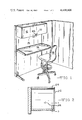
- FIG. 1 is a perspective view of a storage cabinet equipped with the card operable magnetic lock of the present invention shown in relation to an office environment including a work table, room dividers, and swivel chair;
- FIG. 2 is a sectional view of the storage cabinet of FIG. 1 taken along the line 2--2 of FIG. 1;
- FIG. 3 is a sectional view of the locking device of the present invention taken along the line 3--3 of FIG. 2;
- FIG. 4 is a perspective view of the locking device with the inspection panel removed and parts cut away;
- FIG. 5 is a perspective view of a magnetic card for use with the present invention in position for insertion into the door of the storage cabinet of FIG. 1;
- FIG. 6 is a partial perspective view of a magnetic card like that of FIG. 5 but having a magnetizable strip in place of discrete magnetic elements;
- FIG. 7 is a sectional view of the locking device taken along the line 6--6 of FIG. 3;
- FIG. 8 is a sectional view like FIG. 7 showing pivoting of a tumbler member in response to insertion of a properly encoded magnetic card.
- FIG. 1 the card operable magnetic lock of the present invention, indicated generally at 10, is illustrated in FIG. 1 as it would appear in an office environment having a typical storage cabinet 12 equipped with the device.
- the storage cabinet 12 is shown mounted upon a vertical wall divider 14 which also supports a work table 16.
- a rollable swivel chair or stool 18 faces the wall divider 14 to facilitate use of the work table 16 and allow access to the storage cabinet 12.
- the magnetic lock 10 of the present invention is secured to the inside bottom surface of the cabinet door 20 by means of wood or sheet metal screws 22.
- the cabinet door 20 is supported upon pins, not shown, adjacent its upper edge which slide within tracks 24 to provide pivoting and guiding of the cabinet door 20 from its closed vertical position shown in FIG. 2 to a substantially horizontal open position inside the storage cabinet 12 adjacent the tracks 24.
- a narrow slot 26 is provided in the cabinet door 20 adjacent the magnetic lock 10 to provide magnetic card access to the lock mechanism.
- the magnetic lock 10 includes a generally horizontal rectangular box shaped housing 28 having internal support flanges 30 which form a channel to slidably mount an elongated non-magnetic plate member 32 for longitudinal back and forth movement within the housing.
- the housing 28 also includes external mounting flanges 34 at the ends thereof to facilitate attachment of the mounting screws 22.
- Mounting ears 36 extend from the end walls of the housing 28 to facilitate installation and removal of an inspection panel 38 by means of mounting screws 39, as shown in FIGS. 7 and 8.
- a longitudinally extending alignment and stop slot 40 is provided in the top wall of the housing 28 for the insertion of an alignment and stop tab 42 of the plate member 32 to maintain the plate member in position between the support flanges 30 and to limit the longitudinal movement thereof.
- a compression spring 44 abuts one end wall of the housing 28 and engages a spring tab 46 formed in the plate member 32 to bias the plate member to one limit of its longitudinal travel.
- the plate member 32 also includes recesses or notches 48 which are regularly spaced longitudinally along its upper edge. As shown in FIGS. 3 and 4, these recesses 48 have radiused portions 50 extending toward the end of the plate member 32 adjacent the compression spring 44 but are otherwise of square transverse configuration.
- the plate member 32 projects downward to form a hook 52 which is engageable with a fixed bottom portion 54 of the storage cabinet 12, as shown in FIGS. 7 and 8, to secure the cabinet door 20 in the closed position.
- a beveled striker tab 56 is provided on the hook 52 to slidably engage the bottom portion 54 so as to displace the plate member 32 longitudinally to facilitate closing and latching of the cabinet door 20.
- the housing 28 also includes an internal pivot bar 58 which is generally cylindrical in shape and has its axis aligned parallel to and somewhat above the recesses 48 along the upper edge of the plate member 32.
- the pivot bar 48 has a series of annular channels 60 which are spaced longitudinally thereon so as to be in alignment with the recesses 48 of the plate member 32.
- a plurality of tumbler members 62 is pivotably mounted in the annular channels 60.
- Each of the tumbler members 62 is of generally flat rectangular configuration with a book-shaped contour 64 formed along one side thereof to permit hanging of the tumber members 62 in the annular channels 60 so as to be transverse of the pivot bar 58.
- the hook shaped contour 64 is formed symmetrically with respect to the ends of the tumbler member to permit an alternative installation of the tumbler member in a reversed end-for-end orientation.
- FIG. 4 shows the lagoon shaped cutout of the tumbler members 62 of the preferred embodiment which provides this reversible feature.
- the balance point provided by the hook shaped contour 64 is such that each of the tumbler members 62 is biased by the force of gravity into engagement in the respective recess 48 to prevent relative movement of the plate member 32. It is within the purview of this invention to accomplish the biasing of the tumbler members by a variety of means such as compression, tension torsion, or coil springs rather than solely by the specific structure that is illustrated. Applicant points out that utilization of the locking device in non-horizontal applications is possible with such alternative biasing means. Tumbler magnets 65 are mounted on the tumbler members 62 to establish north (stippled) and south magnetic poles at the opposite ends thereof.
- the magnetic card 68 includes a plurality of discrete magnets 70 which are spaced along an edge thereof as shown in FIG. 5 so as to be positionable adjacent the upper ends of the tumbler members 62.
- the magnetic card 68 has a conventional credit card configuration and includes a magnetizable strip 72 which is embedded within or cemented upon a suitable plastic base material along one edge of the card.
- the magnetizable strip can be easily erased and reprogrammed to provide the desired polarity equivalent to that of the discrete magnets 70.
- the construction of the magnetic card 68 is of sufficient stiffness and durability ot permit its use as an abutment means to manually actuate the plate member 32.
- each of the pivotable tumbler members 62 is biased by the force of gravity into engagement in the recesses 48 of the plate member 32 as shown in FIG. 6.
- the hook 52 of the plate member 32 engages the bottom portion 54 of the storage cabinet 12 to prevent opening of the cabinet door 20.
- the position of the hook 52 is maintained in engaging relationship with the bottom portion 54 by the engagement of the tumbler members 62 in the recesses 48.
- the recesses 48 are radiused only along the portions 50 as previously described so as to facilitate the free pivoting of the tumbler members 62 without interfering with the locking of the plate member.
- each tumbler member 62 Upon insertion of the magnetic card 68 having the proper polarity of the discrete magnets 70 or magnetizable strip 72, as shown in FIG. 7, the upper end of each tumbler member 62 is urged laterally and downward. These forces result from magnetic repulsion between alike magnetic poles of the tumbler magnets 70 at the upper end of the tumbler members 62 and of the adjacent magnets 70 or 72. Due to the pivotal mounting of the tumbler members 62 upon the pivot bar 58, the magnetic repulsion results in a pivoting of each tumbler member 62 about the pivot bar 58 such that the lower end of each tumbler member is pivoted out of engagement in the associated recess 48. Alternatively, magnetic attraction between opposite magnetic poles could be utilized to urge the tumbler members out of engagement with the plate member.
- the initial insertion of the magnetic card 68 is transverse with respect to the plate member 32 and the pivot bar 58. This movement is guided by the channel 67 and the narrow slot 26 of the cabinet door 20.
- the location of the magnetic card 68 is further defined by the stop surface 74 terminating the channel 67 and by the alignment tab 42 of the plate member 32 which provides a longitudinal stop.
- the compression spring 44 which was compressed by the longitudinal displacement of the plate member 32, returns the plate 32 to its normal position in which the alignment tab 42 is stopped by the end of the alignment slot 40 which is opposite the compression spring.
- the tumbler members 62 are again pivoted about the pivot bar 58 by the force of gravity so as to engage the recesses 48 and lock the hook 52 of the plate member 32 in engaging position with respect to the bottom portion 54 of the storage cabinet 12.
- the striker tab 56 facilitates latching of the cabinet door 20 by slidably engaging the bottom portion 54 to momentarily compress the compression spring 44.
- an operator of the locking device merely opens the cabinet door 20 using the old magnetic code, removes the inspection panel 38 which is secured by means of the mounting ears 36 and the mounting screws 39, and manually removes and inverts one or more of the tumbler members 62 as indicated by the arrows in FIG. 4.
- the magnetic card 68 is then reprogrammed to the new magnetic code by means of a conventional magnetic encoding device.
- the present invention provides an improved card operable magnetic lock which is simple in construction, economical to produce, and conveniently reprogrammed to new magnetic codes.
- the magnetic lock of the present invention provides a mechanically operable access control for storage cabinets, lockers, doors, and similar devices without the need for electrical actuation of a latch. While the preferred embodiment has been described in considerable detail, the present invention is not to be limited to such detail, except as may be necessitated by the appended claims.
Landscapes
- Engineering & Computer Science (AREA)
- Mechanical Engineering (AREA)
- Lock And Its Accessories (AREA)
Abstract
Description
Claims (21)
Priority Applications (1)
| Application Number | Priority Date | Filing Date | Title |
|---|---|---|---|
| US06/262,841 US4409806A (en) | 1981-05-12 | 1981-05-12 | Locking system using codable magnetic cards |
Applications Claiming Priority (1)
| Application Number | Priority Date | Filing Date | Title |
|---|---|---|---|
| US06/262,841 US4409806A (en) | 1981-05-12 | 1981-05-12 | Locking system using codable magnetic cards |
Publications (1)
| Publication Number | Publication Date |
|---|---|
| US4409806A true US4409806A (en) | 1983-10-18 |
Family
ID=22999292
Family Applications (1)
| Application Number | Title | Priority Date | Filing Date |
|---|---|---|---|
| US06/262,841 Expired - Lifetime US4409806A (en) | 1981-05-12 | 1981-05-12 | Locking system using codable magnetic cards |
Country Status (1)
| Country | Link |
|---|---|
| US (1) | US4409806A (en) |
Cited By (6)
| Publication number | Priority date | Publication date | Assignee | Title |
|---|---|---|---|---|
| US4644766A (en) * | 1983-10-04 | 1987-02-24 | Avant Incorporated | Non-electronic card-key actuated combination lock |
| US4838058A (en) * | 1986-07-10 | 1989-06-13 | Matsumoto Metal Mfg. Co., Ltd. | Card lock |
| US5385039A (en) * | 1993-01-21 | 1995-01-31 | Steelcase Inc. | Electronic lock |
| WO2012154577A2 (en) * | 2011-05-10 | 2012-11-15 | Adc Telecommunications, Inc. | Telecommunications enclosure |
| US9150338B2 (en) | 2011-05-10 | 2015-10-06 | Tyco Electronics Raychem Bvba | Locking system for enclosures |
| WO2018122063A1 (en) * | 2016-12-30 | 2018-07-05 | Verisure Sàrl | A device comprising a casing and a cover releasably connected to the casing by a latching mechanism, and a method for releasing a cover from a casing |
Citations (4)
| Publication number | Priority date | Publication date | Assignee | Title |
|---|---|---|---|---|
| US2384208A (en) * | 1944-05-25 | 1945-09-04 | Neptune Meters Ltd | Magnetic lock |
| US2557028A (en) * | 1946-02-09 | 1951-06-12 | Deutsch Lock Company | Key-operable permutation lock |
| US3831986A (en) * | 1972-08-09 | 1974-08-27 | S Kobayashi | Container having magnetic and latch fastening means |
| US3837193A (en) * | 1972-12-22 | 1974-09-24 | G Csurgay | Magnetic combination door lock |
-
1981
- 1981-05-12 US US06/262,841 patent/US4409806A/en not_active Expired - Lifetime
Patent Citations (4)
| Publication number | Priority date | Publication date | Assignee | Title |
|---|---|---|---|---|
| US2384208A (en) * | 1944-05-25 | 1945-09-04 | Neptune Meters Ltd | Magnetic lock |
| US2557028A (en) * | 1946-02-09 | 1951-06-12 | Deutsch Lock Company | Key-operable permutation lock |
| US3831986A (en) * | 1972-08-09 | 1974-08-27 | S Kobayashi | Container having magnetic and latch fastening means |
| US3837193A (en) * | 1972-12-22 | 1974-09-24 | G Csurgay | Magnetic combination door lock |
Cited By (7)
| Publication number | Priority date | Publication date | Assignee | Title |
|---|---|---|---|---|
| US4644766A (en) * | 1983-10-04 | 1987-02-24 | Avant Incorporated | Non-electronic card-key actuated combination lock |
| US4838058A (en) * | 1986-07-10 | 1989-06-13 | Matsumoto Metal Mfg. Co., Ltd. | Card lock |
| US5385039A (en) * | 1993-01-21 | 1995-01-31 | Steelcase Inc. | Electronic lock |
| WO2012154577A2 (en) * | 2011-05-10 | 2012-11-15 | Adc Telecommunications, Inc. | Telecommunications enclosure |
| WO2012154577A3 (en) * | 2011-05-10 | 2013-03-21 | Adc Telecommunications, Inc. | Telecommunications enclosure |
| US9150338B2 (en) | 2011-05-10 | 2015-10-06 | Tyco Electronics Raychem Bvba | Locking system for enclosures |
| WO2018122063A1 (en) * | 2016-12-30 | 2018-07-05 | Verisure Sàrl | A device comprising a casing and a cover releasably connected to the casing by a latching mechanism, and a method for releasing a cover from a casing |
Similar Documents
| Publication | Publication Date | Title |
|---|---|---|
| US3995460A (en) | Magnetic card key operated door lock structure | |
| WO1998057015A1 (en) | Electromechanical cylinder lock with rotary release | |
| AU617759B2 (en) | Magnetic key operated lock | |
| US10487541B1 (en) | Combination lock with electronic override key | |
| KR0166392B1 (en) | Magnetic locks | |
| US5865483A (en) | Electromechanical locking system | |
| GB1439505A (en) | Magnetic locks | |
| US4602491A (en) | Combination lock | |
| US4409806A (en) | Locking system using codable magnetic cards | |
| US3742739A (en) | Magnetic lock | |
| JPH08226263A (en) | Locking device using card key | |
| US4114410A (en) | Locking device and means for actuating this device | |
| EP0626031B1 (en) | Mechanical card lock | |
| US2384208A (en) | Magnetic lock | |
| DE3728072A1 (en) | INSTALLATION FOR USE OF LOCKERS OR THE LIKE | |
| US3705277A (en) | Multi-code, tamper proof, card-operable magnetic locking mechanism | |
| GB2054029A (en) | Panic door | |
| US5884511A (en) | Mechanical card lock | |
| US4644766A (en) | Non-electronic card-key actuated combination lock | |
| KR960011526B1 (en) | Magnetic key operated lock | |
| US2985005A (en) | Combination lock | |
| RU2130537C1 (en) | Coded lock | |
| KR101103385B1 (en) | Window rotation handle | |
| GB1324349A (en) | Magnetic locking mechanism | |
| US4009600A (en) | Bit key lock |
Legal Events
| Date | Code | Title | Description |
|---|---|---|---|
| AS | Assignment |
Owner name: HERMAN MILLER, INC., ZEELAND, MI A CORP. OF MI Free format text: ASSIGNMENT OF ASSIGNORS INTEREST.;ASSIGNOR:PROPST, ROBERT L.;REEL/FRAME:003892/0678 Effective date: 19810413 |
|
| STCF | Information on status: patent grant |
Free format text: PATENTED CASE |
|
| MAFP | Maintenance fee payment |
Free format text: PAYMENT OF MAINTENANCE FEE, 4TH YEAR, PL 96-517 (ORIGINAL EVENT CODE: M170); ENTITY STATUS OF PATENT OWNER: LARGE ENTITY Year of fee payment: 4 |
|
| MAFP | Maintenance fee payment |
Free format text: PAYMENT OF MAINTENANCE FEE, 8TH YEAR, PL 96-517 (ORIGINAL EVENT CODE: M171); ENTITY STATUS OF PATENT OWNER: LARGE ENTITY Year of fee payment: 8 |
|
| FEPP | Fee payment procedure |
Free format text: PAYOR NUMBER ASSIGNED (ORIGINAL EVENT CODE: ASPN); ENTITY STATUS OF PATENT OWNER: LARGE ENTITY |
|
| MAFP | Maintenance fee payment |
Free format text: PAYMENT OF MAINTENANCE FEE, 12TH YEAR, LARGE ENTITY (ORIGINAL EVENT CODE: M185); ENTITY STATUS OF PATENT OWNER: LARGE ENTITY Year of fee payment: 12 |