US4340154A - Caulker for dispensing two viscous components - Google Patents
Caulker for dispensing two viscous components Download PDFInfo
- Publication number
- US4340154A US4340154A US06/206,886 US20688680A US4340154A US 4340154 A US4340154 A US 4340154A US 20688680 A US20688680 A US 20688680A US 4340154 A US4340154 A US 4340154A
- Authority
- US
- United States
- Prior art keywords
- inner chamber
- chamber
- caulker
- plunger
- outer chamber
- Prior art date
- Legal status (The legal status is an assumption and is not a legal conclusion. Google has not performed a legal analysis and makes no representation as to the accuracy of the status listed.)
- Expired - Lifetime
Links
Images


Classifications
-
- B—PERFORMING OPERATIONS; TRANSPORTING
- B65—CONVEYING; PACKING; STORING; HANDLING THIN OR FILAMENTARY MATERIAL
- B65D—CONTAINERS FOR STORAGE OR TRANSPORT OF ARTICLES OR MATERIALS, e.g. BAGS, BARRELS, BOTTLES, BOXES, CANS, CARTONS, CRATES, DRUMS, JARS, TANKS, HOPPERS, FORWARDING CONTAINERS; ACCESSORIES, CLOSURES, OR FITTINGS THEREFOR; PACKAGING ELEMENTS; PACKAGES
- B65D35/00—Pliable tubular containers adapted to be permanently or temporarily deformed to expel contents, e.g. collapsible tubes for toothpaste or other plastic or semi-liquid material; Holders therefor
- B65D35/24—Pliable tubular containers adapted to be permanently or temporarily deformed to expel contents, e.g. collapsible tubes for toothpaste or other plastic or semi-liquid material; Holders therefor with auxiliary devices
- B65D35/242—Pliable tubular containers adapted to be permanently or temporarily deformed to expel contents, e.g. collapsible tubes for toothpaste or other plastic or semi-liquid material; Holders therefor with auxiliary devices for mixing or discharging of two or more components
Definitions
- Caulkers that are widely used as dispensing containers for sealants, adhesives, and caulking compounds have not been available for two component materials such as epoxies that require separate storage of highly viscous materials and mixing these materials together immediately before use.
- the two component dispensers that exist for liquids, pastry decoration, and other light duty purposes are not suitable for highly viscous, resinous materials presently used in two component adhesives and sealants.
- My inventive caulker dispenses two viscous components contained in two separate, molded resin chambers.
- a generally cylindrical outer chamber contains a collapsible inner chamber having accordion pleats that fold in a predetermined accordion collapse when compressed.
- the inner chamber has a rear end filling opening, and a molded resin plunger is secured to the rear end of the inner chamber and shaped to fit closely within the outer chamber.
- the forward regions of both chambers are joined, and passageways from each chamber merge at the forward end of the caulker.
- An openable barrier seals the forward end of the inner chamber, and a removable closure element seals the forward end of the outer chamber.
- a static mixer and nozzle are attached to the forward end of the outer chamber in communication with the passageways after the barrier seal is opened and the closure element is removed.
- the plunger then advances within the outer chamber while collapsing the inner chamber to force both components from their chambers through the passageways, static mixer, and nozzle.
- FIG. 1 is a partially cut away, side elevational view of a preferred embodiment of the inventive caulker fully loaded and sealed with a cap;
- FIG. 2 is a partially cut away, side elevational view of the caulker of FIG. 1 with the contents partially dispensed through a nozzle;
- FIG. 3 is an enlarged, fragmentary cross-sectional view of the forward region of the caulker of FIG. 1;
- FIG. 4 is an enlarged, fragmentary cross-sectional view of the forward region of the caulker of FIG. 2;
- FIG. 5 is an enlarged, fragmentary cross-sectional view of an alernative preferred embodiment of a caulker according to my invention
- FIG. 6 is an enlarged, fragmentary cross-sectional view of the forward region of another alternative preferred embodiment of my invention.
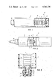
- FIG. 7 is an enlarged, fragmentary cross-sectional view of the rear region of another preferred embodiment of my invention.
- My illustrated preferred embodiment uses an accordion-pleated, collapsible inner chamber 11 arranged within a generally cylindrical outer chamber 12 in which a plunger 13 is fitted.
- One component 14 is stored in outer chamber 12 around inner chamber 11, and the other component 15 is stored within inner chamber 11.
- Advancing plunger 13 then collapses inner chamber 11 to force component 15 forward and also presses component 14 forward with a piston action so that both components are expelled at the forward end of the caulker.
- the preferred way to accomplish this is explained below relative to FIGS. 3 and 4.
- Outer chamber 12 is generally cylindrical and molded of resin material in dimensions that preferably fit existing caulking guns and dispensing equipment so that caulker 10 can be used just like existing caulkers. Forming caulker 10 of plastic materials also keeps the cost low, protects both the stored components, and takes advantage of known technology in the caulker art.
- Inner chamber 11 is also molded of resin material with preformed accordion pleats 16 shaped to fold in a predetermined accordion collapse when inner chamber 11 is axially compressed.
- Chamber 11 is preferably arranged concentrically within chamber 12 as illustrated, but can also be axially offset, have a shape other than cylindrical, and even be divided to hold more than one component.
- Its rear end has a filling opening 17 and external screw threads 18 that mate with a threaded socket 19 on plunger 13. This allows collapsible chamber 11 to be filled with component 15 via rear opening 17, which is then closed by screwing socket 19 of plunger 13 over threads 18.
- Plunger 13 thus serves both as a closure cap and mounting support for inner chamber 11 and as a piston dispenser sliding within outer chamber 12.
- Inner chamber 11 also has an external thread 20 formed on its forward end for screwing into a socket 21 formed in the forward end of outer chamber 12 as best shown in FIGS. 3 and 4. This anchors inner chamber 11 securely relative to the forward end of outer chamber 12.
- An openable barrier 22 closes the forward end of inner chamber 11, and barrier 22 is removable around a line of weakness 23 to open inner chamber 11 for dispensing. Foil seals secured in place and molded tips that can be cut away are alternative possibilities for sealing the forward end of chamber 11.
- outer chamber 12 has an external screw thread 25 on a neck 27 on which closure cap 26 is screwed to seal the forward end of caulker 10 before use.
- Radial spacer fins 28 support threaded socket 21 within neck 27 and also form a passageway 29 for component 14.
- Closure cap 26 is shaped to fit snugly against the forward surfaces of neck 27 and socket 21 to close off and seal passageway 29. Cap 26 also preferably fits snugly against the forward end of inner chamber 11 so that both components are securely sealed in place before use.
- Caulker 10 also includes a dispenser nozzle 30 with a static mixer 31 in a dispensing passageway forming an output from caulker 10.
- Nozzle 30 screws onto thread 25 in place of cap 26.
- passageway 29 for component 14 is opened up; and when barrier 22 is removed, the forward end of chamber 11 forms an open passageway for component 15.
- components 14 and 15 are forced forward by plunger 13 to merge within nozzle 30 and mix together as they are forced through static mixer 31 and dispensed from caulker 10.
- nozzle 30 can be unscrewed and replaced with cap 26, which is preferably shaped to seat and seal both the inner and outer chambers to protect both components. Cap 26 can bear against several surfaces of each chamber for this purpose.
- a foil seal adhered to the forward end of outer chamber 12 can be substituted for screw cap 26, especially for caulkers intended for the building trades, with their dispensing equipment and relatively rapid consumption.
- Chamber 11 can be filled either before or after it is screwed into chamber 12, and plunger 13 doubles as a cap for chamber 11.
- Chamber 12 is preferably filled from the front after chamber 11 is in place, and chambers 11 and 12 can be properly dimensioned to dispense components 14 and 15 in the right proportions.
- FIGS. 5-7 show several other alternatives for practicing the invention.
- a pouch 40 can be arranged within inner chamber 11 to hold component 15.
- Pouch 40 can be formed in generally known ways of foil, resin, or foil and resin laminates that can securely seal in component 15.
- Using a pouch 40 within inner chamber 11 also allows caulker 10 to serve as a three-component dispenser because one component can be placed within pouch 40, the remainder of inner chamber 11 can be filled with another component around pouch 40, and a third component can be filled into outer chamber 12 around inner chamber 11.
- chamber cap 41 can be used without vent holes 42 for closing the rear end of chamber 11 when it is directly filled with component 15 or filled with a third component surrounding pouch 40.
- Pouch 40 has to be punctured or torn near its forward end before dispensing begins, and a preferred way of accommodating this is shown in FIG. 5.
- Barrier 22 for inner chamber 11 is formed as a rounded tip that can be cut off to open a dispensing passageway 43 from inner chamber 11. Then a puncturing tool such as a nail or awl can be inserted through passage 43 and into pouch 40 to puncture the forward end of pouch 40 and allow its contents to escape through passageway 43 as chamber 11 collapses.
- FIG. 6 Another way of puncturing pouch 40 as shown in FIG. 6 is with a needle 45 that is pushed into dispenser passageway 43 to puncture bag 40 before nozzle 30 is screwed in place.
- pouch 40 can be made large enough to hold a volume equal to the full volume of chamber 11 and extend rearwardly of chamber 11 before use.
- Outer chamber 12 is preferably extended rearwardly as illustrated in FIG. 7 to accommodate a longer pouch 40 for this purpose.
- Pouch 40 can then be opened and emptied into chamber 11 just before dispensing begins, and chamber 11 can be closed with an unvented chamber cap 41.
- Nozzle 30 and cap 41 can be stored in the space around pouch 40 provided by elongating outer chamber 12 so that all necessary components are available in a single package.
Landscapes
- Engineering & Computer Science (AREA)
- Mechanical Engineering (AREA)
- Containers And Packaging Bodies Having A Special Means To Remove Contents (AREA)
- Coating Apparatus (AREA)
Abstract
Description
Claims (14)
Priority Applications (3)
| Application Number | Priority Date | Filing Date | Title |
|---|---|---|---|
| US06/206,886 US4340154A (en) | 1980-10-24 | 1980-11-14 | Caulker for dispensing two viscous components |
| CA000387911A CA1166205A (en) | 1980-10-24 | 1981-10-14 | Caulker for dispensing two viscous components |
| JP1981158222U JPS5937501Y2 (en) | 1980-10-24 | 1981-10-23 | Two types of extrusion tools for distributing viscous components |
Applications Claiming Priority (2)
| Application Number | Priority Date | Filing Date | Title |
|---|---|---|---|
| US20047480A | 1980-10-24 | 1980-10-24 | |
| US06/206,886 US4340154A (en) | 1980-10-24 | 1980-11-14 | Caulker for dispensing two viscous components |
Related Parent Applications (1)
| Application Number | Title | Priority Date | Filing Date |
|---|---|---|---|
| US20047480A Continuation-In-Part | 1980-10-24 | 1980-10-24 |
Publications (1)
| Publication Number | Publication Date |
|---|---|
| US4340154A true US4340154A (en) | 1982-07-20 |
Family
ID=26895792
Family Applications (1)
| Application Number | Title | Priority Date | Filing Date |
|---|---|---|---|
| US06/206,886 Expired - Lifetime US4340154A (en) | 1980-10-24 | 1980-11-14 | Caulker for dispensing two viscous components |
Country Status (3)
| Country | Link |
|---|---|
| US (1) | US4340154A (en) |
| JP (1) | JPS5937501Y2 (en) |
| CA (1) | CA1166205A (en) |
Cited By (57)
| Publication number | Priority date | Publication date | Assignee | Title |
|---|---|---|---|---|
| GB2173862A (en) * | 1985-04-17 | 1986-10-22 | Wool Dev Int | Fluid dispensing cartridge |
| US4676657A (en) * | 1985-09-30 | 1987-06-30 | Alexander Botrie | Cartridge for the dispensing of two component systems from caulking guns |
| US4691845A (en) * | 1985-05-31 | 1987-09-08 | Minnesota Mining And Manufacturing Company | Dispensing container |
| EP0249701A2 (en) * | 1986-04-15 | 1987-12-23 | Three Bond Co., Ltd. | Cartridge for 2-part composition |
| US4826047A (en) * | 1988-06-30 | 1989-05-02 | E. I. Du Pont De Nemours And Company | Hand held dispenser for mixing and dispensing two viscous components |
| US4826044A (en) * | 1988-05-31 | 1989-05-02 | Owens-Illinois Closure Inc. | Dispenser for viscous fluids |
| US4846373A (en) * | 1982-09-07 | 1989-07-11 | Penn Laurence R | Apparatus for proportioning or for proportioning and mixing plural different fluid compositions |
| US5076464A (en) * | 1988-02-23 | 1991-12-31 | Patrick Simon | Deformable tubular container |
| US5209376A (en) * | 1992-03-13 | 1993-05-11 | The Procter & Gamble Company | Co-dispensing pump for fluent materials |
| US5301842A (en) * | 1991-03-06 | 1994-04-12 | Frank Ritter | Multicomponent cartridge for plastic materials |
| US5310091A (en) * | 1993-05-12 | 1994-05-10 | Tremco, Inc. | Dual product dispenser |
| US5386928A (en) * | 1993-11-15 | 1995-02-07 | Minnesota Mining And Manufacturing Company | Dual collapsible tube dispensing assembly |
| US5401169A (en) * | 1993-06-10 | 1995-03-28 | Minnesota Mining And Manufacturing | Multiple-part dental material delivery system |
| US5462208A (en) * | 1994-08-01 | 1995-10-31 | The Procter & Gamble Company | Two-phase dispensing systems utilizing bellows pumps |
| US5647510A (en) * | 1993-08-20 | 1997-07-15 | Keller; Wilhelm A. | Multiple component metering and relative proportioning device with collapsible cartridge |
| US6129243A (en) * | 1995-10-16 | 2000-10-10 | Chesebrough-Pond's Usa Co., Division Of Conopco, Inc. | Dual tube dispenser and adaptor |
| WO2001044065A1 (en) * | 1999-12-14 | 2001-06-21 | Green Ronald D | Collapsible dispensing system |
| US6431413B2 (en) | 2000-07-05 | 2002-08-13 | Robert E. Corba | Valve assembly for dispensing container |
| US6454129B1 (en) * | 1999-12-14 | 2002-09-24 | Ronald D. Green | Collapsible dispensing system |
| US6464108B2 (en) | 2000-07-05 | 2002-10-15 | Robert E. Corba | Container assembly for dispensing non-atomized composition mixed internally upon dispensing |
| US6464112B2 (en) | 1999-09-09 | 2002-10-15 | Sashco, Inc. | Dispensing cartridges having collapsible packages for use in caulking guns |
| US6609634B2 (en) * | 2000-09-08 | 2003-08-26 | L'oreal S.A. | Dispensing device and methods |
| US6634524B1 (en) * | 1999-09-14 | 2003-10-21 | Fischbach Kg Kunststoff-Technik | Two-component cartridge for free-flowing media |
| US6681957B1 (en) | 2002-07-17 | 2004-01-27 | Ronald D. Green | Collapsible dispensing system |
| US20040074927A1 (en) * | 2002-10-18 | 2004-04-22 | Lafond Luc Marcel | Portable gas powered fluid dispenser |
| US20040159678A1 (en) * | 2002-03-12 | 2004-08-19 | Chemque, Incorporated | Apparatus and method for mixing and dispensing components of a composition |
| US20040226968A1 (en) * | 2003-03-04 | 2004-11-18 | Lafond Luc Marcel | Nozzle for dispensable viscous materials |
| US20040239113A1 (en) * | 2003-05-30 | 2004-12-02 | Christian Hefele | Quick fastener |
| US20050085786A1 (en) * | 2003-10-15 | 2005-04-21 | Armin Baessler | Head part for a multi-chamber tube bag |
| US6935541B1 (en) | 2004-08-17 | 2005-08-30 | Black & Decker Inc. | Caulk gun pressurizing system |
| US20050198927A1 (en) * | 1999-09-09 | 2005-09-15 | Elliot Summons | Method of filling dispensing cartridges having collapsible packages |
| US20050230433A1 (en) * | 2004-04-20 | 2005-10-20 | Campbell David C | Pressure release connection and pneumatic dispensing device |
| US20050230434A1 (en) * | 2004-04-20 | 2005-10-20 | Campbell David C | Dispensing device using multiple gas cartridges |
| US20050247740A1 (en) * | 2004-05-07 | 2005-11-10 | Daniel Puzio | Pneumatic dispensing device with frangible seal breaker and method |
| US20060027604A1 (en) * | 2004-08-05 | 2006-02-09 | Daniel Puzio | Pressure regulator and dispensing device |
| US20060043120A1 (en) * | 2004-08-27 | 2006-03-02 | Campbell David C | Cordless DC caulk gun |
| US20060043119A1 (en) * | 2004-08-25 | 2006-03-02 | Gibbons Louis A | Dispensing device with rack and pinion drive for nozzle valve |
| US20060144854A1 (en) * | 2004-12-30 | 2006-07-06 | Plas-Pak Industries, Inc. | Cartridge delivery system utilizing film bags |
| US20060165020A1 (en) * | 2004-11-24 | 2006-07-27 | Allen Schultz | Audio conference system |
| EP1698562A2 (en) * | 2005-03-04 | 2006-09-06 | Cosmolab Inc. | Multi-reservoir container with applicator tip |
| EP1849529A1 (en) * | 2006-04-25 | 2007-10-31 | Exchem plc | Cartridge |
| US20080123465A1 (en) * | 2005-01-26 | 2008-05-29 | Rolf Heusser | Multicomponent Foil-Type Container |
| US20090065532A1 (en) * | 2004-11-05 | 2009-03-12 | Luc Marcel Lafond | Dispensing device with secondary reservoir |
| US20090084815A1 (en) * | 2007-10-01 | 2009-04-02 | Mario Paetow | Foil container with foil bag chambers which are arranged next to one another |
| US20090134110A1 (en) * | 2007-11-28 | 2009-05-28 | David Carl Jones | Bottle and valve for holding and dispensing multiple substances |
| US20090179045A1 (en) * | 2006-02-07 | 2009-07-16 | Stephen Cadden | Nozzle and/or adaptor unit on cartridge |
| US20090272761A1 (en) * | 2006-04-11 | 2009-11-05 | Rawlplug Limited | Improved dispensing apparatus |
| US20100108709A1 (en) * | 2004-12-30 | 2010-05-06 | Plas-Pak Industries | Cartridge delivery system utilizing film bags |
| US20100155424A1 (en) * | 2008-12-18 | 2010-06-24 | Wen-Chi Tsai | Double component container |
| CN101065298B (en) * | 2004-11-25 | 2010-12-22 | 费希尔厂有限责任两合公司 | Multi-component cartridge |
| US20110226812A1 (en) * | 2010-03-17 | 2011-09-22 | Yonyu Plastics Co., Ltd. | Fluid dispenser device |
| GB2491405A (en) * | 2011-06-03 | 2012-12-05 | Fastfix It Entpr Co Ltd | Two-part substance dispensing cartridge |
| WO2013141720A1 (en) * | 2012-03-22 | 2013-09-26 | Andrew Leo Haynes | A flow restrictor |
| US9517488B2 (en) | 2004-12-30 | 2016-12-13 | Plas-Pak Industries, Inc. | Component delivery system utilizing film bags |
| US20170311999A1 (en) * | 2016-04-28 | 2017-11-02 | Heraeus Medical Gmbh | Storage and mixing system with compressible internal cartridge for pasty starting components |
| US10865016B2 (en) * | 2017-08-09 | 2020-12-15 | New Direction Packaging | Squeezable container and dispenser assembly and method of use |
| US11596972B2 (en) | 2019-01-03 | 2023-03-07 | Medmix Switzerland Ag | Coaxial cartridge for multi-component materials and method of assembling a coaxial cartridge |
Citations (6)
| Publication number | Priority date | Publication date | Assignee | Title |
|---|---|---|---|---|
| US1698404A (en) * | 1923-10-16 | 1929-01-08 | Gilmont Products Corp | Ultiple-compartment collapsible tube |
| US3266671A (en) * | 1963-12-16 | 1966-08-16 | Gelpey Kenneth | Compartmented dispenser for plural fluids |
| US3323682A (en) * | 1965-10-06 | 1967-06-06 | Chem Dev Corp | Disposable cartridge for gun-type dispensers |
| US3813011A (en) * | 1971-05-11 | 1974-05-28 | S Harrison | Aerosol can for dispensing materials in fixed volumetric ratio |
| US3976223A (en) * | 1972-02-02 | 1976-08-24 | Carter-Wallace, Inc. | Aerosol package |
| US4147282A (en) * | 1977-06-06 | 1979-04-03 | Sidney Levy | Vacuum actuated pressurized fluid dispenser |
-
1980
- 1980-11-14 US US06/206,886 patent/US4340154A/en not_active Expired - Lifetime
-
1981
- 1981-10-14 CA CA000387911A patent/CA1166205A/en not_active Expired
- 1981-10-23 JP JP1981158222U patent/JPS5937501Y2/en not_active Expired
Patent Citations (6)
| Publication number | Priority date | Publication date | Assignee | Title |
|---|---|---|---|---|
| US1698404A (en) * | 1923-10-16 | 1929-01-08 | Gilmont Products Corp | Ultiple-compartment collapsible tube |
| US3266671A (en) * | 1963-12-16 | 1966-08-16 | Gelpey Kenneth | Compartmented dispenser for plural fluids |
| US3323682A (en) * | 1965-10-06 | 1967-06-06 | Chem Dev Corp | Disposable cartridge for gun-type dispensers |
| US3813011A (en) * | 1971-05-11 | 1974-05-28 | S Harrison | Aerosol can for dispensing materials in fixed volumetric ratio |
| US3976223A (en) * | 1972-02-02 | 1976-08-24 | Carter-Wallace, Inc. | Aerosol package |
| US4147282A (en) * | 1977-06-06 | 1979-04-03 | Sidney Levy | Vacuum actuated pressurized fluid dispenser |
Cited By (83)
| Publication number | Priority date | Publication date | Assignee | Title |
|---|---|---|---|---|
| US4846373A (en) * | 1982-09-07 | 1989-07-11 | Penn Laurence R | Apparatus for proportioning or for proportioning and mixing plural different fluid compositions |
| GB2173862A (en) * | 1985-04-17 | 1986-10-22 | Wool Dev Int | Fluid dispensing cartridge |
| US4691845A (en) * | 1985-05-31 | 1987-09-08 | Minnesota Mining And Manufacturing Company | Dispensing container |
| US4676657A (en) * | 1985-09-30 | 1987-06-30 | Alexander Botrie | Cartridge for the dispensing of two component systems from caulking guns |
| EP0249701B1 (en) * | 1986-04-15 | 1992-01-29 | Three Bond Co., Ltd. | Cartridge for 2-part composition |
| EP0249701A2 (en) * | 1986-04-15 | 1987-12-23 | Three Bond Co., Ltd. | Cartridge for 2-part composition |
| US5076464A (en) * | 1988-02-23 | 1991-12-31 | Patrick Simon | Deformable tubular container |
| US4826044A (en) * | 1988-05-31 | 1989-05-02 | Owens-Illinois Closure Inc. | Dispenser for viscous fluids |
| EP0344914A1 (en) * | 1988-05-31 | 1989-12-06 | Owens-Illinois Closure Inc., | Dispenser for viscous fluids |
| US4826047A (en) * | 1988-06-30 | 1989-05-02 | E. I. Du Pont De Nemours And Company | Hand held dispenser for mixing and dispensing two viscous components |
| US5301842A (en) * | 1991-03-06 | 1994-04-12 | Frank Ritter | Multicomponent cartridge for plastic materials |
| US5209376A (en) * | 1992-03-13 | 1993-05-11 | The Procter & Gamble Company | Co-dispensing pump for fluent materials |
| US5310091A (en) * | 1993-05-12 | 1994-05-10 | Tremco, Inc. | Dual product dispenser |
| US5401169A (en) * | 1993-06-10 | 1995-03-28 | Minnesota Mining And Manufacturing | Multiple-part dental material delivery system |
| US5647510A (en) * | 1993-08-20 | 1997-07-15 | Keller; Wilhelm A. | Multiple component metering and relative proportioning device with collapsible cartridge |
| US5386928A (en) * | 1993-11-15 | 1995-02-07 | Minnesota Mining And Manufacturing Company | Dual collapsible tube dispensing assembly |
| US5462208A (en) * | 1994-08-01 | 1995-10-31 | The Procter & Gamble Company | Two-phase dispensing systems utilizing bellows pumps |
| US6129243A (en) * | 1995-10-16 | 2000-10-10 | Chesebrough-Pond's Usa Co., Division Of Conopco, Inc. | Dual tube dispenser and adaptor |
| US6464112B2 (en) | 1999-09-09 | 2002-10-15 | Sashco, Inc. | Dispensing cartridges having collapsible packages for use in caulking guns |
| US20050198927A1 (en) * | 1999-09-09 | 2005-09-15 | Elliot Summons | Method of filling dispensing cartridges having collapsible packages |
| US7194847B2 (en) | 1999-09-09 | 2007-03-27 | Sashco, Inc. | Method of filling dispensing cartridges having collapsible packages |
| US20020162859A1 (en) * | 1999-09-09 | 2002-11-07 | Summons Wayne L. | Method of filling dispensing cartridges having collapsible packages |
| US6634524B1 (en) * | 1999-09-14 | 2003-10-21 | Fischbach Kg Kunststoff-Technik | Two-component cartridge for free-flowing media |
| US6454129B1 (en) * | 1999-12-14 | 2002-09-24 | Ronald D. Green | Collapsible dispensing system |
| WO2001044065A1 (en) * | 1999-12-14 | 2001-06-21 | Green Ronald D | Collapsible dispensing system |
| US6464108B2 (en) | 2000-07-05 | 2002-10-15 | Robert E. Corba | Container assembly for dispensing non-atomized composition mixed internally upon dispensing |
| US6431413B2 (en) | 2000-07-05 | 2002-08-13 | Robert E. Corba | Valve assembly for dispensing container |
| US6609634B2 (en) * | 2000-09-08 | 2003-08-26 | L'oreal S.A. | Dispensing device and methods |
| US20040159678A1 (en) * | 2002-03-12 | 2004-08-19 | Chemque, Incorporated | Apparatus and method for mixing and dispensing components of a composition |
| US6971787B2 (en) * | 2002-03-12 | 2005-12-06 | Chemque, Incorporated | Apparatus and method for mixing and dispensing components of a composition |
| US6681957B1 (en) | 2002-07-17 | 2004-01-27 | Ronald D. Green | Collapsible dispensing system |
| US20040074927A1 (en) * | 2002-10-18 | 2004-04-22 | Lafond Luc Marcel | Portable gas powered fluid dispenser |
| US7163130B2 (en) | 2002-10-18 | 2007-01-16 | Luc Marcel Lafond | Portable gas powered fluid dispenser |
| US20040226968A1 (en) * | 2003-03-04 | 2004-11-18 | Lafond Luc Marcel | Nozzle for dispensable viscous materials |
| US20040239113A1 (en) * | 2003-05-30 | 2004-12-02 | Christian Hefele | Quick fastener |
| US7370777B2 (en) * | 2003-05-30 | 2008-05-13 | Hilti Aktiengesellschaft | Quick fastener |
| US20050085786A1 (en) * | 2003-10-15 | 2005-04-21 | Armin Baessler | Head part for a multi-chamber tube bag |
| US7510546B2 (en) * | 2003-10-15 | 2009-03-31 | Hilti Aktiengesellschaft | Head part for a multi-chamber tube bag |
| US20050230434A1 (en) * | 2004-04-20 | 2005-10-20 | Campbell David C | Dispensing device using multiple gas cartridges |
| US20050230433A1 (en) * | 2004-04-20 | 2005-10-20 | Campbell David C | Pressure release connection and pneumatic dispensing device |
| US7275663B2 (en) | 2004-04-20 | 2007-10-02 | Black & Decker Inc. | Dispensing device using multiple gas cartridges |
| US7188753B2 (en) | 2004-04-20 | 2007-03-13 | Black & Decker Inc. | Pressure release connection and pneumatic dispensing device |
| US20050247740A1 (en) * | 2004-05-07 | 2005-11-10 | Daniel Puzio | Pneumatic dispensing device with frangible seal breaker and method |
| US20060027604A1 (en) * | 2004-08-05 | 2006-02-09 | Daniel Puzio | Pressure regulator and dispensing device |
| US6935541B1 (en) | 2004-08-17 | 2005-08-30 | Black & Decker Inc. | Caulk gun pressurizing system |
| US20060043119A1 (en) * | 2004-08-25 | 2006-03-02 | Gibbons Louis A | Dispensing device with rack and pinion drive for nozzle valve |
| US7185792B2 (en) | 2004-08-25 | 2007-03-06 | Black & Decker Inc. | Dispensing device with rack and pinion drive for nozzle valve |
| US20060043120A1 (en) * | 2004-08-27 | 2006-03-02 | Campbell David C | Cordless DC caulk gun |
| US7261220B2 (en) | 2004-08-27 | 2007-08-28 | Black & Decker Inc. | Cordless DC caulk gun |
| US20090065532A1 (en) * | 2004-11-05 | 2009-03-12 | Luc Marcel Lafond | Dispensing device with secondary reservoir |
| US20060165020A1 (en) * | 2004-11-24 | 2006-07-27 | Allen Schultz | Audio conference system |
| CN101065298B (en) * | 2004-11-25 | 2010-12-22 | 费希尔厂有限责任两合公司 | Multi-component cartridge |
| US20060144854A1 (en) * | 2004-12-30 | 2006-07-06 | Plas-Pak Industries, Inc. | Cartridge delivery system utilizing film bags |
| US9968959B2 (en) | 2004-12-30 | 2018-05-15 | Nordson Corporation | Component delivery system utilizing film bags |
| US10525500B2 (en) | 2004-12-30 | 2020-01-07 | Nordson Corporation | Component delivery system utilizing film bags |
| US10625293B2 (en) | 2004-12-30 | 2020-04-21 | Nordson Corporation | Component delivery system utilizing film bags |
| US9517488B2 (en) | 2004-12-30 | 2016-12-13 | Plas-Pak Industries, Inc. | Component delivery system utilizing film bags |
| US20100108709A1 (en) * | 2004-12-30 | 2010-05-06 | Plas-Pak Industries | Cartridge delivery system utilizing film bags |
| US7934864B2 (en) * | 2005-01-26 | 2011-05-03 | Sulzer Mixpac Ag | Multicomponent foil-type container |
| US20080123465A1 (en) * | 2005-01-26 | 2008-05-29 | Rolf Heusser | Multicomponent Foil-Type Container |
| US20060198686A1 (en) * | 2005-03-04 | 2006-09-07 | Cosmolab Inc. | Multi-reservoir container with applicator tip and method of making the same |
| EP1698562A2 (en) * | 2005-03-04 | 2006-09-06 | Cosmolab Inc. | Multi-reservoir container with applicator tip |
| US7435027B2 (en) | 2005-03-04 | 2008-10-14 | Cosmolab Inc. | Multi-reservoir container with applicator tip and method of making the same |
| EP1698562A3 (en) * | 2005-03-04 | 2006-10-18 | Cosmolab Inc. | Multi-reservoir container with applicator tip |
| US8172109B2 (en) | 2006-02-07 | 2012-05-08 | Rawlplug Limited | Nozzle and/or adaptor unit on cartridge |
| US20090179045A1 (en) * | 2006-02-07 | 2009-07-16 | Stephen Cadden | Nozzle and/or adaptor unit on cartridge |
| US20090272761A1 (en) * | 2006-04-11 | 2009-11-05 | Rawlplug Limited | Improved dispensing apparatus |
| US8281956B2 (en) * | 2006-04-11 | 2012-10-09 | Stephen Cadden | Dispensing apparatus |
| EP1849529A1 (en) * | 2006-04-25 | 2007-10-31 | Exchem plc | Cartridge |
| US20070257068A1 (en) * | 2006-04-25 | 2007-11-08 | Exchem Plc | Cartridge |
| US8028859B2 (en) * | 2007-10-01 | 2011-10-04 | Hilti Aktiengesellschaft | Foil container with foil bag chambers which are arranged next to one another |
| US20090084815A1 (en) * | 2007-10-01 | 2009-04-02 | Mario Paetow | Foil container with foil bag chambers which are arranged next to one another |
| US20090134110A1 (en) * | 2007-11-28 | 2009-05-28 | David Carl Jones | Bottle and valve for holding and dispensing multiple substances |
| US20100155424A1 (en) * | 2008-12-18 | 2010-06-24 | Wen-Chi Tsai | Double component container |
| US20110226812A1 (en) * | 2010-03-17 | 2011-09-22 | Yonyu Plastics Co., Ltd. | Fluid dispenser device |
| GB2491405A (en) * | 2011-06-03 | 2012-12-05 | Fastfix It Entpr Co Ltd | Two-part substance dispensing cartridge |
| US9943876B2 (en) | 2012-03-22 | 2018-04-17 | DFund Limited | Flow restrictor |
| WO2013141720A1 (en) * | 2012-03-22 | 2013-09-26 | Andrew Leo Haynes | A flow restrictor |
| US10596590B2 (en) | 2012-03-22 | 2020-03-24 | DFund Limited | Flow restrictor |
| US20170311999A1 (en) * | 2016-04-28 | 2017-11-02 | Heraeus Medical Gmbh | Storage and mixing system with compressible internal cartridge for pasty starting components |
| US10166057B2 (en) * | 2016-04-28 | 2019-01-01 | Heraeus Medical Gmbh | Storage and mixing system with compressible internal cartridge for pasty starting components |
| US10865016B2 (en) * | 2017-08-09 | 2020-12-15 | New Direction Packaging | Squeezable container and dispenser assembly and method of use |
| US11596972B2 (en) | 2019-01-03 | 2023-03-07 | Medmix Switzerland Ag | Coaxial cartridge for multi-component materials and method of assembling a coaxial cartridge |
Also Published As
| Publication number | Publication date |
|---|---|
| JPS5937501Y2 (en) | 1984-10-17 |
| JPS5795369U (en) | 1982-06-11 |
| CA1166205A (en) | 1984-04-24 |
Similar Documents
| Publication | Publication Date | Title |
|---|---|---|
| US4340154A (en) | Caulker for dispensing two viscous components | |
| EP0093185A1 (en) | Caulker for dispensing two viscous components | |
| US5088627A (en) | Multi-chamber package for mixing and dispensing | |
| US6454129B1 (en) | Collapsible dispensing system | |
| EP0631558B1 (en) | Dual chamber dispenser | |
| CN110304351B (en) | Dispenser | |
| US4208133A (en) | Injection cartridge | |
| US4099651A (en) | Closure assembly for collapsible tube dispensers, and the like | |
| US5667102A (en) | Cartridge with an exchangeable content package | |
| CA2560340C (en) | Pump dispenser and sealed cartridge inserted into container and broken by dip tube | |
| US8016808B2 (en) | Device for piercing film bags | |
| HU204185B (en) | Two-chamber mixture-feeding tank | |
| US6609634B2 (en) | Dispensing device and methods | |
| US4261481A (en) | Fluid packaging kit for pressurized dispensing | |
| EP0624403A1 (en) | Dual product dispenser | |
| HU215250B (en) | Container for fluid materials | |
| CA2572799A1 (en) | A syringe assembly | |
| CA2480392A1 (en) | A multi-compartment syringe | |
| CA2558473A1 (en) | A cartridge unit for a multi-compartment container assembly | |
| CA2358943A1 (en) | Collapsible dispensing system | |
| EP0754633B1 (en) | Reusable multi-compartment cartrige system | |
| US5425475A (en) | Epoxy dispenser | |
| RU2649511C2 (en) | Film capacity for the delivering device and method of manufacture of film capacity | |
| US4298119A (en) | Multiple compartment containers | |
| RU2403195C2 (en) | Device for storage and application of liquid and/or paste-type matters |
Legal Events
| Date | Code | Title | Description |
|---|---|---|---|
| AS | Assignment |
Owner name: VOPLEX CORPORATION, 1100 PITTSFORD-VICTOR RD., PIT Free format text: ASSIGNMENT OF ASSIGNORS INTEREST.;ASSIGNOR:VAN MANEN, DICK T.;REEL/FRAME:003951/0061 Effective date: 19801110 Owner name: VOPLEX CORPORATION, A CORP.OF NY., NEW YORK Free format text: ASSIGNMENT OF ASSIGNORS INTEREST;ASSIGNOR:VAN MANEN, DICK T.;REEL/FRAME:003951/0061 Effective date: 19801110 Owner name: VOPLEX CORPORATION, NEW YORK Free format text: ASSIGNMENT OF ASSIGNORS INTEREST;ASSIGNOR:VAN MANEN, DICK T.;REEL/FRAME:003951/0061 Effective date: 19801110 |
|
| STCF | Information on status: patent grant |
Free format text: PATENTED CASE |
|
| AS | Assignment |
Owner name: BANKERS TRUST COMPANY, NEW YORK Free format text: ASSIGNMENT OF SECURITY INTEREST;ASSIGNOR:CAMBRIDGE INDUSTRIES, INC.;REEL/FRAME:007854/0613 Effective date: 19951117 |
|
| AS | Assignment |
Owner name: BANK OF AMERICA, N.A., CALIFORNIA Free format text: ASSIGNMENT OF SECURITY INTEREST;ASSIGNOR:CAMBRIDGE ACQUISITION CORP.;REEL/FRAME:011149/0335 Effective date: 20000714 |
|
| AS | Assignment |
Owner name: CAMBRIDGE INDUSTRIES, INC., MICHIGAN Free format text: RELEASE OF SECURITY INTEREST;ASSIGNOR:BANKERS TRUST COMPANY;REEL/FRAME:011511/0860 Effective date: 20000425 |