US4285355A - Tent - Google Patents
Tent Download PDFInfo
- Publication number
- US4285355A US4285355A US06/089,960 US8996079A US4285355A US 4285355 A US4285355 A US 4285355A US 8996079 A US8996079 A US 8996079A US 4285355 A US4285355 A US 4285355A
- Authority
- US
- United States
- Prior art keywords
- brackets
- tubes
- pair
- tent
- cover
- Prior art date
- Legal status (The legal status is an assumption and is not a legal conclusion. Google has not performed a legal analysis and makes no representation as to the accuracy of the status listed.)
- Expired - Lifetime
Links
Images


Classifications
-
- E—FIXED CONSTRUCTIONS
- E04—BUILDING
- E04H—BUILDINGS OR LIKE STRUCTURES FOR PARTICULAR PURPOSES; SWIMMING OR SPLASH BATHS OR POOLS; MASTS; FENCING; TENTS OR CANOPIES, IN GENERAL
- E04H15/00—Tents or canopies, in general
- E04H15/32—Parts, components, construction details, accessories, interior equipment, specially adapted for tents, e.g. guy-line equipment, skirts, thresholds
- E04H15/34—Supporting means, e.g. frames
- E04H15/42—Supporting means, e.g. frames external type, e.g. frame outside cover
Definitions
- This invention relates to tents, and, more particularly, to a tent which is easy to erect and which is stable without being attached to the ground.
- Tent design is subject to a number of competing considerations. For example, it is usually desirable that a tent be easy to erect, roomy, and stable. Tents which are intended for use by backpackers should also be lightweight. However, the tents which are the easiest to erect are often relatively small. Tents which are relatively roomy are more difficult to erect and may be relatively heavy.
- the invention provides a tent which is easy to erect, roomy, and lightweight.
- the tent can be erected without being attached to the ground so that the tent can be pitched on rocky ground or other hard surfaces and can be moved to a new location without disassembly.
- a pair of unique brackets interconnect a ridge pole, a pair of spreader rods, and two pairs of upright poles.
- the upright poles are pivotally connected to the bracket, and when the tent is erected and the upright poles are connected to the tent fabric, the upright poles are restrained from pivoting in either direction so that the tent is maintained in a stable condition.
- a fly can be used to cover the tent without attaching the fly to the ground.
- a fly support rod is connected to each of the brackets, and the fly is supported by the ridge pole, the spreader rods, and the fly support rods.
- Elastic straps are used to connect the corners of the fly to the lower ends of the upright poles.
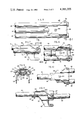
- FIG. 1 is a perspective view of a tent formed in accordance with the invention
- FIG. 2 is a perspective view of the tent of FIG. 1 without the fly;
- FIG. 3 is an exploded perspective view of the frame assembly of the tent
- FIG. 4 is a perspective view of one of the brackets in a folded condition
- FIG. 5 is a fragmentary perspective view of one of the brackets in an unfolded condition
- FIG. 6 is a fragmentary top plan view of the bracket of FIG. 4;
- FIG. 7 is a fragmentary side elevational view of the bracket taken along the line 7--7 of FIG. 6;
- FIG. 8 is a fragmentary bottom plan view of the bracket
- FIG. 9 is an end elevational view of the bracket taken along the line 9--9 of FIG. 7;
- FIG. 10 is a fragmentary top plan view of the unfolded bracket of FIG. 5;
- FIG. 11 is a fragmentary side elevational view of the unfolded bracket
- FIG. 12 is a perspective view of the tent fabric laid on the ground before erecting the tent;
- FIG. 13 illustrates the spreader rods being connected to the tent fabric
- FIG. 14 is a fragmentary perspective view showing one of the brackets connected to one of the spreader rods
- FIG. 15 illustrates the second bracket being connected to the other spreader rod
- FIG. 16 is a fragmentary perspective view of one of the brackets after both brackets are connected to the spreader rods;
- FIG. 17 is a perspective view of the tent showing the fly being attached
- FIG. 18 is a perspective view similar to FIG. 16 showing the attachment of one of the fly support rods to one of the brackets;
- FIG. 19 is an enlarged fragmentary perspective view showing the connection between the fly and one of the fly support rods
- FIG. 20 is an enlarged fragmentary perspective view showing the connection between the bottom of one of the upright poles and the tent fabric and the fly;
- FIG. 21 is a fragmentary perspective view of one of the enforcing patches on the fly.
- a tent 25 comprises a cover or tent fabric 26, a frame assembly 27, and a fly 28.
- the tent fabric includes a top portion 29, a bottom portion 30, a pair of side portions 31 and 32, and a pair of end portions 33 and 34 which form a tent enclosure.
- the various portions of the tent fabric can be provided by panels which are stitched together.
- the side portion 31 includes a generally rectangular door panel 35 which can be detached from the remainder of the side portion around three sides by a slide fastener 36.
- the door panel is rolled up and secured by ties 37.
- Each of the end portions of the tent fabric is provided with a window 38 which is covered with mesh fabric.
- the frame assembly is illustrated in FIG. 3 and includes a pair of brackets 39 and 40, each of which includes three tubes 41, 42 and 43; a ridge pole 44, which is connected to each of the tubes 41 of the brackets; four spreader rods 45-48, which are connected to the brackets; eight upright pole sections 49-56 which are connected to the tubes 42 and 43 of the brackets; and two fly support rods 57 and 58, which are telescopingly connected to the tubes 41 of the brackets.
- the spreader rod 45 has a sleeve 59 attached thereto so that the spreader rod 46 can be connected to the spreader rod 45 by inserting the spreader rod 46 into the sleeve.
- the spreader rod 47 includes a sleeve 60 for connecting the spreader rods 47 and 48.
- the brackets 39 and 40 are identical, and the details of bracket 39 are illustrated in FIGS. 4-11.
- the bracket includes upper and lower mounting plates 62 and 63 which are connected to the tube 41 by a rivet 64.
- the upper mounting plate includes a flat central portion 65 and a pair of angled side portions 66 and 67 which diverge outwardly from the central portion to form an included angle of about 110° (see particularly FIG. 9).
- the bottom mounting plate similarly includes a flat central portion 68 and a pair of angled side portions 69 and 70 which extend parallel to the corresponding portions of the upper mounting plate.
- a pair of hook portions 71 and 72 extend from the side portions generally perpendicularly to the central portion 68.
- the end of the lower mounting plate opposite the hook portions terminates in a curved trough 73 (FIGS. 8 and 11) which extends through a transversely extending tab portion 74 on the upper mounting plate.
- the tube 41 also extends through the tab portion and is thereby prevented from pivoting with respect to the rivet 64.
- the tube 42 is pivotally connected to the side portions 66 and 69 of the upper and lower mounting plates by a rivet 76
- the tube 43 is pivotally connected to the side portions 67 and 70 of the upper and lower mounting plates by a rivet 77.
- the tubes 42 and 43 are pivotable between a storage position illustrated in FIGS. 4 and 6-8 in which the tubes extends alongside and parallel to the stationary tube 41 and an unfolded position illustrated in FIGS. 5, 10, and 11 in which the tubes 42 and 43 extend parallel to but away from the middle tube 41.
- the free ends 78 and 79 (FIG. 4) of the tubes 42 and 43 have a reduced cross section to facilitate inserting the tubes into the upright pole sections 49 and 51 (FIG. 3).
- the tent fabric 26 is illustrated in FIG. 12 laid out on the ground in preparation for erecting the tent.
- a pair of stake loops 81 and 82 are attached to the lower edge of the front side portion 31 of the tent fabric, and a pair of stake loops 83 and 84 are attached to the lower edge of the back side portion 32 of the tent fabric. Stakes 85 are driven through these loops to hold the side portion taut, but the tent can be erected without using these stakes.
- a pair of elastic straps 86 and 87 are attached to the lower corners of the end portion 33 (see also FIG. 20) for securing the upright poles to the tent fabric.
- each elastic strap passes through a ring 88, and a second strap 89 passes through the ring 88 and a second ring 90.
- Identical strap-and-ring assemblies 91 and 92 are attached to the corners of the other end panel 34.
- a ridge sleeve 94 is attached to the middle of the top panel 35 of the tent fabric and extends parallel to the upper and lower edges of the side portions.
- a pair of spaced-apart sleeves 95 and 96 are attached to the top portion at the juncture or seam between the top panel and the end portion 33, and a pair of sleeves 97 and 98 are attached to the seam between the top panel and the other end portion 34.
- the sleeves 95-98 extend generally perpendicularly to the ridge sleeve 94, although in the preferred embodiment each pair of sleeves bows outwardly somewhat away from the ridge sleeve.
- FIG. 13 illustrates the tent after the spreader rods 45 and 46 (see FIG. 3) are joined together by the connecting sleeve 59 and inserted through the tent sleeves 95 and 96.
- the user is in the process of inserting the connected spreader rods 47 and 48 through the sleeves 97 and 98 on the tent fabric.
- the spreader rods are centered within the fabric sleeves so that the metal connecting sleeves 59 and 60 are positioned in the space between the fabric sleeves.
- the ridge pole 44 is inserted through the ridge sleeve 94 on the tent, and one end of the ridge pole is inserted into the middle or stationary tube 41 of the bracket 40.
- the tube 41 is provided with a stop which limits the distance which the ridge pole can be inserted into the tube to, for example, about two inches.
- the pivotable tubes 42 and 43 of the bracket 40 are unfolded before the ridge pole is inserted into the tube 41, and the hook portions 71 and 72 of the lower mounting plate are hooked over the metal connecting sleeve 60 (FIG. 14).
- FIG. 15 illustrates the user pulling the spreader rod 45 with one hand while pushing on the unfolded tubes 42 and 43 of the bracket with the other hand.
- the spreader rods and the ridge pole are formed of flexible and resilient material such as fiberglass to facilitate the flexing of the spreader rods, and the ridge pole will bow upwardly as shown in FIGS. 15 and 17 to permit the hook portions of the bracket 39 to be passed over the connecting sleeve 59. Once the hook portions are in place, the tensioned ridge pole and brackets will maintain a separating force on the spreader rods and will maintain the top of the tent stretched and taut.
- the four pairs of upright pole sections 49-50, 51-52, 53-54, and 55-56 are joined together and inserted over the tapered ends of the tubes 42 and 43 of the two brackets 39 and 40.
- Each of the upright pole sections has a tapered end to facilitate its insertion into the untapered end of another pole section.
- the upright pole sections and the tubes 42 and 43 can then be pivoted away from each other. Since the tubes 42 and 43 are secured to the angled portions of the upper and lower mounting plates (see, e.g., FIG. 9) pivoting the tubes 42 and 43 away from parallelism with the middle tube 41 will cause the ends of the upright poles to move downwardly relative to the tube 41.
- the upright poles will therefore support the ridge pole above the ground as illustrated in FIG. 2.
- the ends of the upright poles will move apart.
- the tapered lower ends of the upright poles are inserted through the rings 88 (FIG. 20) which are attached to the four corners of the tent by the elastic straps 86.
- the second ring 90 can be used to pull the ring 88 into position below the end of the upright pole.
- the ends of the upright poles are prevented from being spread apart any farther then they are in FIG. 2 by the taut end portions 33 and 34.
- the ends of the upright poles are prevented from being moved toward each other by the taut side portions 31 and 32.
- the tubes 41 and 42 In order for the ends of the upright poles at one end of the tent to be moved toward each other, the tubes 41 and 42 must pivot upwardly toward parallelism with the tube 41 and the distance between the ends of the upright poles at one end of the tent and the upright poles at the other end of the tent must be increased. This is prevented by the side panels of the tent fabric. It will therefore be appreciated that the combination of the various frame members and the tent fabric act together to resist any force, e.g., the weight of the tent, which tends to change the angle between the upright poles.
- the tent is therefore supported in a stable manner without being attached to the ground.
- the stakes 85 at the front and back of the tent are not necessary to support the tent, and the erected tent can be moved by removing the stakes and picking the tent up by the ridge pole or the upright poles.
- the tubes 42 and 43 are in position to maintain the connecting sleeves 59 and 60 of the spreader rods in the hook portions of the brackets 39 and 40. This is illustrated in FIG. 16.
- the engagement between the connecting sleeves and the tubes 42 and 43 not only prevents the spreader rods from being disconnected from the brackets but also provides a stop which prevents the tubes 42 and 43 from pivoting too far toward perpendicularity with the tube 41. Accordingly, the force required to prevent further separation of the ends of the upright poles need not be provided entirely by the tent fabric but can also be provided by the engagement of the tubes 42 and 43 with the connecting sleeves.
- the upright poles can be further secured if desired by driving stakes through the four corner rings 90 into the ground.
- FIG. 17 illustrates the fly or cover 28 being attached to the tent.
- fly support rods 57 and 58 are inserted into the ends of the tubes 41 and 42 of the brackets 39 and 40 (compare FIGS. 16 and 18).
- the fly is a generally rectangular sheet, and sleeves 101 (FIGS. 17 and 19) are attached to opposite edges of the fly along the midline.
- the ends of the fly support poles 57 and 58 are inserted into the sleeves, and the fly is spread over the top of the tent.
- An elastic strap 102 is attached to each corner of the fly, and an S-shaped hook 103 (FIG. 20) is attached to the end of each elastic strap.
- Each of the S hooks is hooked to the lower end of one of the upright poles to draw the fly taut over the top of the tent.
- the fly covers the windows 38 in the end portions and the upper portion of the door opening so that the windows can be opened to prevent condensation inside the tent under humid conditions.
- the fly is drawn outwardly over the ends of the spreader rods 45-48, and four reinforcing pads 104 (FIGS. 1 and 21) are sewn to the bottom surface of the fly to prevent the rods from poking through the fly.
- the tent is disassembled by following the reverse procedure, and the tent can be erected and disassembled in a matter of minutes.
- the brackets 39 and 40 can be folded into a compact storage configuration shown in FIG. 4, and the folded brackets and the individual pole sections can be very short, for example, less than two feet long.
- the tent fabric can be a lightweight material such as nylon, and the brackets and upright pole sections can be aluminum. Accordingly, the tent is lightweight and can be carried compactly by a backpacker.
- the unique support system of the invention provides a number of advantages, including:
- the tent support system allows the fly to protect the windows from all forms of precipitation so that the windows may be opened to prevent condensation inside the tent;
- a plurality of interconnected ridge poles can be used with a tent that has a longer top portion in order to provide additional head room inside the tent and more vertical end walls.
Landscapes
- Engineering & Computer Science (AREA)
- Architecture (AREA)
- Civil Engineering (AREA)
- Structural Engineering (AREA)
- Tents Or Canopies (AREA)
Abstract
Description
Claims (15)
Priority Applications (1)
| Application Number | Priority Date | Filing Date | Title |
|---|---|---|---|
| US06/089,960 US4285355A (en) | 1979-10-31 | 1979-10-31 | Tent |
Applications Claiming Priority (1)
| Application Number | Priority Date | Filing Date | Title |
|---|---|---|---|
| US06/089,960 US4285355A (en) | 1979-10-31 | 1979-10-31 | Tent |
Publications (1)
| Publication Number | Publication Date |
|---|---|
| US4285355A true US4285355A (en) | 1981-08-25 |
Family
ID=22220394
Family Applications (1)
| Application Number | Title | Priority Date | Filing Date |
|---|---|---|---|
| US06/089,960 Expired - Lifetime US4285355A (en) | 1979-10-31 | 1979-10-31 | Tent |
Country Status (1)
| Country | Link |
|---|---|
| US (1) | US4285355A (en) |
Cited By (47)
| Publication number | Priority date | Publication date | Assignee | Title |
|---|---|---|---|---|
| US4355650A (en) * | 1980-06-02 | 1982-10-26 | Jean Beaudry | Portable shelter |
| US4541445A (en) * | 1984-05-24 | 1985-09-17 | Oyster Tent Company | Tent |
| US4709718A (en) * | 1985-05-09 | 1987-12-01 | Nichols Philip T | Tent fly apparatus and method |
| US5035012A (en) * | 1989-08-02 | 1991-07-30 | Gleason Corporation | Portable hammock kit and improved portable hammock |
| US5168889A (en) * | 1989-11-08 | 1992-12-08 | Diestel Daniel G | Wheelchair weather breaker cover |
| US5185972A (en) * | 1991-02-27 | 1993-02-16 | Markiewicz Richard A | Modular canopy |
| US5255698A (en) * | 1992-04-13 | 1993-10-26 | Orville Riley | Collapsible tent frame |
| WO1995019483A1 (en) * | 1994-01-18 | 1995-07-20 | Lynch James P | Configurable shade structure |
| US5638848A (en) * | 1993-11-09 | 1997-06-17 | Acadamy Broadway Corp. | Tent |
| US5638850A (en) * | 1994-02-03 | 1997-06-17 | Hazinski; Daniel P. | Tent rain fly and method |
| US6463948B2 (en) * | 1998-07-16 | 2002-10-15 | Youn Jae Lee | Tent with exterior screen house |
| US20040173251A1 (en) * | 2003-04-24 | 2004-09-09 | Robert Cantwell | Waterproof tent |
| US6796320B2 (en) * | 1998-08-07 | 2004-09-28 | Mark C. Carter | Triangular erectable shelter with flexible roof assembly |
| US20050044630A1 (en) * | 2003-08-27 | 2005-03-03 | Danaher Thomas C. | Bed-tent |
| US20050258294A1 (en) * | 2001-03-29 | 2005-11-24 | Dickson Craig C | Backpack |
| US7182092B1 (en) * | 2004-01-30 | 2007-02-27 | North Pole Limited | Tent eve |
| US20070044827A1 (en) * | 2005-08-25 | 2007-03-01 | Yul Lee P | Moisture diversion system for a collapsible structure |
| US20070193614A1 (en) * | 2006-02-21 | 2007-08-23 | Egstad Gary A | High visibility cover for camo hunting blind |
| US20080142065A1 (en) * | 2006-12-14 | 2008-06-19 | Nengsen Chen | Light-duty structural shed or house with skylights |
| US7673642B1 (en) * | 2005-09-06 | 2010-03-09 | Shires Henry C | Single pole freestanding shelter |
| US20110030750A1 (en) * | 2009-03-17 | 2011-02-10 | YJIP, Inc. | Portable shelter having resiliently supported awning |
| US20120125389A1 (en) * | 2009-07-29 | 2012-05-24 | The Coleman Company | Vent for a tent or shelter |
| US20130061896A1 (en) * | 2011-09-12 | 2013-03-14 | Nomadic Comfort Llc | Ventilation panels having curved openings and structures incorporating such ventilation panels |
| US20140076372A1 (en) * | 2012-09-19 | 2014-03-20 | Ki Ho Jin | Foldable tent |
| US8776813B2 (en) | 2010-06-14 | 2014-07-15 | Easton Technical Products, Inc. | Tent pole connection system and methods |
| US8893737B2 (en) * | 2012-12-25 | 2014-11-25 | Zhenjiang Hengfeng Top Leisure Co., Ltd. | Tent skeleton and tent |
| US20150167344A1 (en) * | 2013-12-12 | 2015-06-18 | Ki Ho Jin | Foldable Tent |
| US20150167346A1 (en) * | 2013-12-17 | 2015-06-18 | Ki Ho Jin | Tent Awning |
| FR3014926A1 (en) * | 2013-12-17 | 2015-06-19 | Decathlon Sa | RECOVERY COVER FOR TENT WITH AN AWNING |
| US20150292231A1 (en) * | 2014-03-21 | 2015-10-15 | Isla Llc | Collapsible sun shelter |
| USD766394S1 (en) | 2015-03-20 | 2016-09-13 | Isla Llc | Sun shelter |
| US20160290001A1 (en) * | 2013-05-08 | 2016-10-06 | Campvalley(Xiamen) Co., Ltd. | Tent having enhanced tent top |
| US20170167158A1 (en) * | 2015-12-11 | 2017-06-15 | Ardisam International, Inc. | Collapsible shelter |
| US20170191285A1 (en) * | 2015-12-30 | 2017-07-06 | Xiamen Roadzup Outdoor Products Co., Ltd. | Tent rack |
| US9752345B1 (en) * | 2016-02-12 | 2017-09-05 | Clam Corporation | Convertible shelter systems |
| US9784009B2 (en) | 2015-03-24 | 2017-10-10 | Campvalley (Xiamen) Co., Ltd. | Integrated tent having multiple tent units |
| US9856673B2 (en) * | 2015-04-01 | 2018-01-02 | Topsun Creative Design | Tent |
| US20180155952A1 (en) * | 2016-12-02 | 2018-06-07 | Plano Molding Company | Enclosure and expansion structure therefor |
| US10012007B2 (en) | 2016-04-07 | 2018-07-03 | Xiamen Innovation Metal Products Co., Ltd. | Tent frame and tent with slidably coupled top poles |
| US10253522B2 (en) | 2013-02-05 | 2019-04-09 | Campvalley (Xiamen) Co., Ltd. | Shelter frame with transverse member |
| US20190116947A1 (en) * | 2017-10-23 | 2019-04-25 | William Kuypers | Portable Sun shade |
| US10329790B2 (en) | 2017-04-21 | 2019-06-25 | Campvalley (Xiamen) Co., Ltd. | Tent frame and tent with extended top |
| USD852917S1 (en) | 2015-03-20 | 2019-07-02 | Isla Llc | Sun shelter |
| US11351079B2 (en) * | 2019-03-22 | 2022-06-07 | Donald Nellis | Vaporizer containment tent |
| JP2022528766A (en) * | 2019-04-10 | 2022-06-15 | ジェイケーエル コーポレイション | tent |
| USD983922S1 (en) * | 2021-04-30 | 2023-04-18 | Jeh Kun LAH | Tent frame |
| WO2024022724A1 (en) * | 2022-07-26 | 2024-02-01 | Decathlon | Tent that has a roof comprising a spacing element |
Citations (9)
| Publication number | Priority date | Publication date | Assignee | Title |
|---|---|---|---|---|
| US2084524A (en) * | 1936-08-11 | 1937-06-22 | Eide Edgar Stanley | Tent frame construction |
| US2963030A (en) * | 1956-02-16 | 1960-12-06 | Robert L Blanchard | Portable collapsible shelter |
| US3058480A (en) * | 1958-06-09 | 1962-10-16 | Robert L Blanchard | Collapsible tent construction |
| US3128781A (en) * | 1962-10-03 | 1964-04-14 | Arthur J Kirkham | Tent |
| US3181542A (en) * | 1963-06-24 | 1965-05-04 | Hawthorn Company Division Of K | Umbrella tent frame |
| US3223098A (en) * | 1963-09-12 | 1965-12-14 | Jr Charles M Dole | Collapsible shelter construction |
| US3367348A (en) * | 1966-08-25 | 1968-02-06 | Arthur J. Kirkham | Tent support and method of erection |
| US3834410A (en) * | 1973-02-27 | 1974-09-10 | Us Army | Collapsible tent |
| US4078572A (en) * | 1976-12-27 | 1978-03-14 | Moss Charles W | Portable shelter |
-
1979
- 1979-10-31 US US06/089,960 patent/US4285355A/en not_active Expired - Lifetime
Patent Citations (9)
| Publication number | Priority date | Publication date | Assignee | Title |
|---|---|---|---|---|
| US2084524A (en) * | 1936-08-11 | 1937-06-22 | Eide Edgar Stanley | Tent frame construction |
| US2963030A (en) * | 1956-02-16 | 1960-12-06 | Robert L Blanchard | Portable collapsible shelter |
| US3058480A (en) * | 1958-06-09 | 1962-10-16 | Robert L Blanchard | Collapsible tent construction |
| US3128781A (en) * | 1962-10-03 | 1964-04-14 | Arthur J Kirkham | Tent |
| US3181542A (en) * | 1963-06-24 | 1965-05-04 | Hawthorn Company Division Of K | Umbrella tent frame |
| US3223098A (en) * | 1963-09-12 | 1965-12-14 | Jr Charles M Dole | Collapsible shelter construction |
| US3367348A (en) * | 1966-08-25 | 1968-02-06 | Arthur J. Kirkham | Tent support and method of erection |
| US3834410A (en) * | 1973-02-27 | 1974-09-10 | Us Army | Collapsible tent |
| US4078572A (en) * | 1976-12-27 | 1978-03-14 | Moss Charles W | Portable shelter |
Cited By (69)
| Publication number | Priority date | Publication date | Assignee | Title |
|---|---|---|---|---|
| US4355650A (en) * | 1980-06-02 | 1982-10-26 | Jean Beaudry | Portable shelter |
| US4541445A (en) * | 1984-05-24 | 1985-09-17 | Oyster Tent Company | Tent |
| US4709718A (en) * | 1985-05-09 | 1987-12-01 | Nichols Philip T | Tent fly apparatus and method |
| US5035012A (en) * | 1989-08-02 | 1991-07-30 | Gleason Corporation | Portable hammock kit and improved portable hammock |
| US5168889A (en) * | 1989-11-08 | 1992-12-08 | Diestel Daniel G | Wheelchair weather breaker cover |
| US5185972A (en) * | 1991-02-27 | 1993-02-16 | Markiewicz Richard A | Modular canopy |
| US5255698A (en) * | 1992-04-13 | 1993-10-26 | Orville Riley | Collapsible tent frame |
| US5638848A (en) * | 1993-11-09 | 1997-06-17 | Acadamy Broadway Corp. | Tent |
| WO1995019483A1 (en) * | 1994-01-18 | 1995-07-20 | Lynch James P | Configurable shade structure |
| US5918614A (en) * | 1994-01-18 | 1999-07-06 | Lynch; James P. | Configurable shade structure including a kit and method therefor |
| US5638850A (en) * | 1994-02-03 | 1997-06-17 | Hazinski; Daniel P. | Tent rain fly and method |
| US6463948B2 (en) * | 1998-07-16 | 2002-10-15 | Youn Jae Lee | Tent with exterior screen house |
| US6796320B2 (en) * | 1998-08-07 | 2004-09-28 | Mark C. Carter | Triangular erectable shelter with flexible roof assembly |
| US20050258294A1 (en) * | 2001-03-29 | 2005-11-24 | Dickson Craig C | Backpack |
| US20080029142A1 (en) * | 2003-04-24 | 2008-02-07 | Robert Cantwell | Tent having an outer skirt and tub floor |
| US20040173251A1 (en) * | 2003-04-24 | 2004-09-09 | Robert Cantwell | Waterproof tent |
| US8161992B2 (en) * | 2003-04-24 | 2012-04-24 | Northpole Limited | Tent having an outer skirt and tub floor |
| US7222635B2 (en) * | 2003-04-24 | 2007-05-29 | North Pole, Ltd. | Tent having an outer skirt and tub floor |
| US6952844B2 (en) * | 2003-08-27 | 2005-10-11 | Danaher Thomas C | Bed-tent |
| US20050274406A1 (en) * | 2003-08-27 | 2005-12-15 | Danaher Thomas C | Bed-tent |
| US7174584B2 (en) | 2003-08-27 | 2007-02-13 | Danaher Thomas C | Bed-tent |
| US20050044630A1 (en) * | 2003-08-27 | 2005-03-03 | Danaher Thomas C. | Bed-tent |
| US7182092B1 (en) * | 2004-01-30 | 2007-02-27 | North Pole Limited | Tent eve |
| US8113224B2 (en) | 2005-08-25 | 2012-02-14 | North Pole Limited | Moisture diversion system for a collapsible structure |
| US7721746B2 (en) * | 2005-08-25 | 2010-05-25 | North Pole Limited | Moisture diversion system for a collapsible structure |
| US20100200036A1 (en) * | 2005-08-25 | 2010-08-12 | Lee Pil Yul | Moisture diversion system for a collapsible structure |
| US20070044827A1 (en) * | 2005-08-25 | 2007-03-01 | Yul Lee P | Moisture diversion system for a collapsible structure |
| US7673642B1 (en) * | 2005-09-06 | 2010-03-09 | Shires Henry C | Single pole freestanding shelter |
| US20070193614A1 (en) * | 2006-02-21 | 2007-08-23 | Egstad Gary A | High visibility cover for camo hunting blind |
| US20080142065A1 (en) * | 2006-12-14 | 2008-06-19 | Nengsen Chen | Light-duty structural shed or house with skylights |
| US20110030750A1 (en) * | 2009-03-17 | 2011-02-10 | YJIP, Inc. | Portable shelter having resiliently supported awning |
| US20120125389A1 (en) * | 2009-07-29 | 2012-05-24 | The Coleman Company | Vent for a tent or shelter |
| JP2013501170A (en) * | 2009-07-29 | 2013-01-10 | ザ・コールマン・カンパニー・インコーポレイテッド | Vent for tent or shelter |
| US8701688B2 (en) * | 2009-07-29 | 2014-04-22 | Nicholas W. Vaughn | Vent for a tent or shelter |
| US8776813B2 (en) | 2010-06-14 | 2014-07-15 | Easton Technical Products, Inc. | Tent pole connection system and methods |
| US20130061896A1 (en) * | 2011-09-12 | 2013-03-14 | Nomadic Comfort Llc | Ventilation panels having curved openings and structures incorporating such ventilation panels |
| US20140076372A1 (en) * | 2012-09-19 | 2014-03-20 | Ki Ho Jin | Foldable tent |
| US9140030B2 (en) * | 2012-09-19 | 2015-09-22 | Ki Ho Jin | Foldable tent |
| US8893737B2 (en) * | 2012-12-25 | 2014-11-25 | Zhenjiang Hengfeng Top Leisure Co., Ltd. | Tent skeleton and tent |
| US10253522B2 (en) | 2013-02-05 | 2019-04-09 | Campvalley (Xiamen) Co., Ltd. | Shelter frame with transverse member |
| US10227792B2 (en) * | 2013-05-08 | 2019-03-12 | Campvalley (Xiamen) Co., Ltd. | Tent having enhanced tent top |
| US20160290001A1 (en) * | 2013-05-08 | 2016-10-06 | Campvalley(Xiamen) Co., Ltd. | Tent having enhanced tent top |
| US9366054B2 (en) * | 2013-12-12 | 2016-06-14 | Ki Ho Jin | Foldable tent |
| US20150167344A1 (en) * | 2013-12-12 | 2015-06-18 | Ki Ho Jin | Foldable Tent |
| FR3014926A1 (en) * | 2013-12-17 | 2015-06-19 | Decathlon Sa | RECOVERY COVER FOR TENT WITH AN AWNING |
| WO2015092231A1 (en) * | 2013-12-17 | 2015-06-25 | Decathlon | Cover for a tent provided with an awning |
| US20150167346A1 (en) * | 2013-12-17 | 2015-06-18 | Ki Ho Jin | Tent Awning |
| US20150292231A1 (en) * | 2014-03-21 | 2015-10-15 | Isla Llc | Collapsible sun shelter |
| US9562368B2 (en) * | 2014-03-21 | 2017-02-07 | Isla Llc | Collapsible sun shelter |
| USD766394S1 (en) | 2015-03-20 | 2016-09-13 | Isla Llc | Sun shelter |
| USD852917S1 (en) | 2015-03-20 | 2019-07-02 | Isla Llc | Sun shelter |
| US9784009B2 (en) | 2015-03-24 | 2017-10-10 | Campvalley (Xiamen) Co., Ltd. | Integrated tent having multiple tent units |
| US9856673B2 (en) * | 2015-04-01 | 2018-01-02 | Topsun Creative Design | Tent |
| US9976318B2 (en) * | 2015-12-11 | 2018-05-22 | Ardisam, Inc. | Collapsible shelter |
| US20170167158A1 (en) * | 2015-12-11 | 2017-06-15 | Ardisam International, Inc. | Collapsible shelter |
| US20170191285A1 (en) * | 2015-12-30 | 2017-07-06 | Xiamen Roadzup Outdoor Products Co., Ltd. | Tent rack |
| US10138652B2 (en) * | 2015-12-30 | 2018-11-27 | Xiamen Roadzup Outdoor Products Co., Ltd. | Foldable tent rack |
| US9752345B1 (en) * | 2016-02-12 | 2017-09-05 | Clam Corporation | Convertible shelter systems |
| US10012007B2 (en) | 2016-04-07 | 2018-07-03 | Xiamen Innovation Metal Products Co., Ltd. | Tent frame and tent with slidably coupled top poles |
| US20180155952A1 (en) * | 2016-12-02 | 2018-06-07 | Plano Molding Company | Enclosure and expansion structure therefor |
| US10633884B2 (en) * | 2016-12-02 | 2020-04-28 | Plano Molding Company | Enclosure and expansion structure therefor |
| US10329790B2 (en) | 2017-04-21 | 2019-06-25 | Campvalley (Xiamen) Co., Ltd. | Tent frame and tent with extended top |
| US20190116947A1 (en) * | 2017-10-23 | 2019-04-25 | William Kuypers | Portable Sun shade |
| US10477930B2 (en) * | 2017-10-23 | 2019-11-19 | William Kuypers | Portable sun shade |
| US11351079B2 (en) * | 2019-03-22 | 2022-06-07 | Donald Nellis | Vaporizer containment tent |
| JP2022528766A (en) * | 2019-04-10 | 2022-06-15 | ジェイケーエル コーポレイション | tent |
| USD983922S1 (en) * | 2021-04-30 | 2023-04-18 | Jeh Kun LAH | Tent frame |
| WO2024022724A1 (en) * | 2022-07-26 | 2024-02-01 | Decathlon | Tent that has a roof comprising a spacing element |
| FR3138462A1 (en) * | 2022-07-26 | 2024-02-02 | Decathlon | Tent having a roof including a spacer |
Similar Documents
| Publication | Publication Date | Title |
|---|---|---|
| US4285355A (en) | Tent | |
| US10364588B2 (en) | Shelter system | |
| US4827958A (en) | Tent | |
| US4632138A (en) | Portable shelter | |
| US4102352A (en) | Insulated tent | |
| US5628338A (en) | Collapsible blind | |
| US7673642B1 (en) | Single pole freestanding shelter | |
| US7178537B2 (en) | Ring and pole connector assembly for a tent corner | |
| US5738130A (en) | Vehicle supported tent | |
| US11639613B2 (en) | Portable room with ceiling pockets | |
| US3965915A (en) | Tent structure | |
| US6273115B1 (en) | Wind and weather protective device in the form of a folding roof and/or partition | |
| US11156012B2 (en) | Convertible hammock-shade tent | |
| WO2001048338A1 (en) | Unitary, collapsible tri-panel structures__ | |
| US11002037B2 (en) | Portable room | |
| US10934738B2 (en) | Portable containment room | |
| US20090242009A1 (en) | Protective shelter | |
| US2059463A (en) | Tent | |
| US20040129307A1 (en) | Collapsible and foldable canvas structure | |
| US11560733B2 (en) | Ten-device-in-one reconfigurable adjustable carport, capable of functioning as privacy screen, wind screen, cabana, dog run, retail-tradeshow booth, attic, storage, picnic table, kennel, and carport | |
| US3943953A (en) | Umbrella tent | |
| US3468321A (en) | Convertible tent structure | |
| US2865385A (en) | Tent | |
| US2793646A (en) | Folding camp tent | |
| JPH0413003Y2 (en) |
Legal Events
| Date | Code | Title | Description |
|---|---|---|---|
| STCF | Information on status: patent grant |
Free format text: PATENTED CASE |
|
| AS | Assignment |
Owner name: CITIBANK, N.A., 399 PARK AVENUE, NEW YORK, NY 1004 Free format text: SECURITY INTEREST;ASSIGNORS:COLEMAN OUTDOOR PRODUCTS, INC.;COLEMAN HEATING AND AIR CONDITIONING PRODUCTS, INC.;CROSMAN PRODUCTS, INC.;AND OTHERS;REEL/FRAME:005260/0006 Effective date: 19890831 |
|
| AS | Assignment |
Owner name: COLEMAN OUTDOOR PRODUCTS, INC., A CORP OF DE, KANS Free format text: RELEASED BY SECURED PARTY;ASSIGNOR:CITIBANK, N.A.,;REEL/FRAME:005427/0464 Effective date: 19900830 Owner name: CREDIT SUISSE, Free format text: SECURITY INTEREST;ASSIGNORS:COLEMAN COMPANY, INC., THE,;COLEMAN OUTDOOR PRODUCTS, INC.,;COLEMAN POWERMATE, INC.,;AND OTHERS;REEL/FRAME:005430/0501 Effective date: 19900830 |
|
| AS | Assignment |
Owner name: COLEMAN COMPANY, INC., THE, KANSAS Free format text: ASSIGNMENT OF ASSIGNORS INTEREST.;ASSIGNOR:COLEMAN OUT DOOR PRODUCTS, INC.;REEL/FRAME:006040/0404 Effective date: 19920226 |
|
| AS | Assignment |
Owner name: COLEMAN COMPANY, INC., THE Free format text: SECURITY INTEREST;ASSIGNOR:CREDIT SUISSE;REEL/FRAME:006083/0007 Effective date: 19920304 |
|
| AS | Assignment |
Owner name: CREDIT SUISSE, NEW YORK Free format text: SECURITY INTEREST;ASSIGNOR:COLEMAN COMPANY, INC., THE;REEL/FRAME:006088/0438 Effective date: 19920226 |
|
| AS | Assignment |
Owner name: FIRST UNION NATIONAL BANK, AS ADMINISTRATIVE AGENT Free format text: SECURITY INTEREST;ASSIGNOR:COLEMAN COMPANY, INC., THE (DELAWARE CORPORATION);REEL/FRAME:010238/0384 Effective date: 19990514 |
|
| AS | Assignment |
Owner name: O'BRIEN INTERNATIONAL, INC. (WA CORPORATION), FLOR Free format text: RELEASE AND REASSIGNMENT;ASSIGNOR:CREDIT SUISSE FIRST BOSTON (NEW YORK BRANCH OF SWISS BANK);REEL/FRAME:011295/0131 Effective date: 20000630 Owner name: COLEMAN COMPANY, INC., THE (KS CORPORATION), FLORI Free format text: RELEASE AND REASSIGNMENT;ASSIGNOR:CREDIT SUISSE FIRST BOSTON (NEW YORK BRANCH OF SWISS BANK);REEL/FRAME:011295/0131 Effective date: 20000630 Owner name: COLEMAN OUTDOOR PRODUCTS, INC. (DE CORPORATION), F Free format text: RELEASE AND REASSIGNMENT;ASSIGNOR:CREDIT SUISSE FIRST BOSTON (NEW YORK BRANCH OF SWISS BANK);REEL/FRAME:011295/0131 Effective date: 20000630 Owner name: COLEMAN POWERMATE, INC. (NE CORPORATION), FLORIDA Free format text: RELEASE AND REASSIGNMENT;ASSIGNOR:CREDIT SUISSE FIRST BOSTON (NEW YORK BRANCH OF SWISS BANK);REEL/FRAME:011295/0131 Effective date: 20000630 Owner name: COLEMAN SPAS, INC. (CA CORPORATION), FLORIDA Free format text: RELEASE AND REASSIGNMENT;ASSIGNOR:CREDIT SUISSE FIRST BOSTON (NEW YORK BRANCH OF SWISS BANK);REEL/FRAME:011295/0131 Effective date: 20000630 Owner name: MASTER CRAFT BOAT COMPANY (TN CORPORATION), FLORID Free format text: RELEASE AND REASSIGNMENT;ASSIGNOR:CREDIT SUISSE FIRST BOSTON (NEW YORK BRANCH OF SWISS BANK);REEL/FRAME:011295/0131 Effective date: 20000630 Owner name: SKEETER PRODUCTS, INC. (TX CORPORATION), FLORIDA Free format text: RELEASE AND REASSIGNMENT;ASSIGNOR:CREDIT SUISSE FIRST BOSTON (NEW YORK BRANCH OF SWISS BANK);REEL/FRAME:011295/0131 Effective date: 20000630 Owner name: SONIFORM, INC. (CA CORPORATION), FLORIDA Free format text: RELEASE AND REASSIGNMENT;ASSIGNOR:CREDIT SUISSE FIRST BOSTON (NEW YORK BRANCH OF SWISS BANK);REEL/FRAME:011295/0131 Effective date: 20000630 Owner name: COLEMAN COMPANY, INC., THE (DE CORPORATION), FLORI Free format text: RELEASE AND REASSIGNMENT;ASSIGNOR:CREDIT SUISSE FIRST BOSTON (NEW YORK BRANCH OF SWISS BANK);REEL/FRAME:011295/0131 Effective date: 20000630 |
|
| AS | Assignment |
Owner name: COLEMAN COMPANY, THE, KANSAS Free format text: TERMINATION AND RELEASE OF SECURITY INTEREST;ASSIGNOR:WACHOVIA BANK, NATIONAL ASSOCIATION (FORMERLY FIRST UNION NATIONAL BANK);REEL/FRAME:013986/0833 Effective date: 20021213 |