US4246024A - Method for the gaseous reduction of metal ores using reducing gas produced by gasification of solid or liquid fossil fuels - Google Patents
Method for the gaseous reduction of metal ores using reducing gas produced by gasification of solid or liquid fossil fuels Download PDFInfo
- Publication number
- US4246024A US4246024A US06/089,902 US8990279A US4246024A US 4246024 A US4246024 A US 4246024A US 8990279 A US8990279 A US 8990279A US 4246024 A US4246024 A US 4246024A
- Authority
- US
- United States
- Prior art keywords
- zone
- reactor
- gas
- cooling
- reducing
- Prior art date
- Legal status (The legal status is an assumption and is not a legal conclusion. Google has not performed a legal analysis and makes no representation as to the accuracy of the status listed.)
- Expired - Lifetime
Links
Images
Classifications
-
- C—CHEMISTRY; METALLURGY
- C21—METALLURGY OF IRON
- C21B—MANUFACTURE OF IRON OR STEEL
- C21B13/00—Making spongy iron or liquid steel, by direct processes
- C21B13/02—Making spongy iron or liquid steel, by direct processes in shaft furnaces
-
- C—CHEMISTRY; METALLURGY
- C21—METALLURGY OF IRON
- C21B—MANUFACTURE OF IRON OR STEEL
- C21B13/00—Making spongy iron or liquid steel, by direct processes
- C21B13/0073—Selection or treatment of the reducing gases
-
- C—CHEMISTRY; METALLURGY
- C21—METALLURGY OF IRON
- C21B—MANUFACTURE OF IRON OR STEEL
- C21B13/00—Making spongy iron or liquid steel, by direct processes
- C21B13/02—Making spongy iron or liquid steel, by direct processes in shaft furnaces
- C21B13/029—Introducing coolant gas in the shaft furnaces
-
- C—CHEMISTRY; METALLURGY
- C21—METALLURGY OF IRON
- C21B—MANUFACTURE OF IRON OR STEEL
- C21B2100/00—Handling of exhaust gases produced during the manufacture of iron or steel
- C21B2100/20—Increasing the gas reduction potential of recycled exhaust gases
- C21B2100/22—Increasing the gas reduction potential of recycled exhaust gases by reforming
-
- C—CHEMISTRY; METALLURGY
- C21—METALLURGY OF IRON
- C21B—MANUFACTURE OF IRON OR STEEL
- C21B2100/00—Handling of exhaust gases produced during the manufacture of iron or steel
- C21B2100/20—Increasing the gas reduction potential of recycled exhaust gases
- C21B2100/24—Increasing the gas reduction potential of recycled exhaust gases by shift reactions
-
- C—CHEMISTRY; METALLURGY
- C21—METALLURGY OF IRON
- C21B—MANUFACTURE OF IRON OR STEEL
- C21B2100/00—Handling of exhaust gases produced during the manufacture of iron or steel
- C21B2100/20—Increasing the gas reduction potential of recycled exhaust gases
- C21B2100/28—Increasing the gas reduction potential of recycled exhaust gases by separation
- C21B2100/282—Increasing the gas reduction potential of recycled exhaust gases by separation of carbon dioxide
-
- C—CHEMISTRY; METALLURGY
- C21—METALLURGY OF IRON
- C21B—MANUFACTURE OF IRON OR STEEL
- C21B2100/00—Handling of exhaust gases produced during the manufacture of iron or steel
- C21B2100/60—Process control or energy utilisation in the manufacture of iron or steel
- C21B2100/64—Controlling the physical properties of the gas, e.g. pressure or temperature
-
- Y—GENERAL TAGGING OF NEW TECHNOLOGICAL DEVELOPMENTS; GENERAL TAGGING OF CROSS-SECTIONAL TECHNOLOGIES SPANNING OVER SEVERAL SECTIONS OF THE IPC; TECHNICAL SUBJECTS COVERED BY FORMER USPC CROSS-REFERENCE ART COLLECTIONS [XRACs] AND DIGESTS
- Y02—TECHNOLOGIES OR APPLICATIONS FOR MITIGATION OR ADAPTATION AGAINST CLIMATE CHANGE
- Y02P—CLIMATE CHANGE MITIGATION TECHNOLOGIES IN THE PRODUCTION OR PROCESSING OF GOODS
- Y02P10/00—Technologies related to metal processing
- Y02P10/10—Reduction of greenhouse gas [GHG] emissions
- Y02P10/122—Reduction of greenhouse gas [GHG] emissions by capturing or storing CO2
-
- Y—GENERAL TAGGING OF NEW TECHNOLOGICAL DEVELOPMENTS; GENERAL TAGGING OF CROSS-SECTIONAL TECHNOLOGIES SPANNING OVER SEVERAL SECTIONS OF THE IPC; TECHNICAL SUBJECTS COVERED BY FORMER USPC CROSS-REFERENCE ART COLLECTIONS [XRACs] AND DIGESTS
- Y02—TECHNOLOGIES OR APPLICATIONS FOR MITIGATION OR ADAPTATION AGAINST CLIMATE CHANGE
- Y02P—CLIMATE CHANGE MITIGATION TECHNOLOGIES IN THE PRODUCTION OR PROCESSING OF GOODS
- Y02P10/00—Technologies related to metal processing
- Y02P10/10—Reduction of greenhouse gas [GHG] emissions
- Y02P10/134—Reduction of greenhouse gas [GHG] emissions by avoiding CO2, e.g. using hydrogen
Definitions
- This invention relates generally to a method for the gaseous reduction of particulate ores to metals in particulate form in a moving bed, vertical shaft reactor, and more particularly, to a method for the reduction of the ore and the cooling of the resulting metal particles using a reducing gas externally supplied from a solid or liquid fossil fuel gasification unit.
- This invention is particularly suitable to the reduction of iron ore to sponge iron and is illustratively described with particular reference thereto.
- the terms "reforming,” “reforming zone,” etc. specifically refer to chemical reactions whereby the H 2 to CO ratio of the reducing gas supplied to the moving bed, vertical shaft reactor is increased.
- the production of sponge iron in a typical vertical shaft, moving bed reactor involves two principal steps, namely, reduction of the ore with a suitable hot reducing gas in a reduction zone of the reactor and then subsequent cooling of the resulting sponge iron with a gaseous coolant in a cooling zone of the reactor.
- the reducing gas is typically a gas largely composed of carbon monoxide and hydrogen injected into the reactor at temperatures in the range of 850° C. to 1100° C., preferably 900° C. to 1000° C.
- the hot reducing gas may be introduced into the reactor at the bottom of the reduction zone and passed upwardly through the reactor to flow counter-currently to the downwardly moving ore, or alternatively, the hot reducing gas may be introduced at the top of the reduction zone and caused to flow co-currently with the downwardly moving ore. It is well known in the art to cool the sponge iron by injecting a cooling gas at relatively low temperature into the cooling zone of the reactor and passing the cooling gas upwardly through the reactor whereby the cooling gas temperature is increased and the temperature of the sponge iron is reduced.
- the reducing gas used in the direct reduction of iron ores has been derived from a number of sources, e.g., the catalytic reforming of hydrocarbons and steam.
- Systems using natural gas and steam to generate a reducing gas require the use of catalytic reforming units.
- additional equipment has been required to enrich the gas so that it may be effectively used for reduction purposes.
- a metal ore e.g., iron ore
- sponge metal e.g., sponge iron
- the objects and advantages of the present invention may be generally achieved by providing a reforming zone within the reactor to reform a reducing gas produced in a suitable gasification unit. Since the gas diffusion rate into the ore particles is essentially temperature independent and depends primarily upon the concentration of hydrogen present in the reducing gas, the reducing gas should desirably have a relatively high hydrogen content.
- a reducing gas which may be prepared by the gasification of coal with oxygen and water vapor is mixed with steam and heated. The heated gas mixture is injected into the reactor and reformed in a reforming zone located in the upper portion of the reactor to produce a higher and more desirable H 2 to CO ratio.
- the H 2 to CO ratio which is typically in the range of about 0.5:1 to 1:1 is raised to a suitable value for iron ore reduction, i.e., in the range of about 2.5:1 to 5:1 by means of the water-gas shift reaction:
- the iron-bearing material in the reactor acts as a particularly effective catalyst for this reaction.
- the composition of a typical effluent gas from a liquid fossil fuel gasifier unit as reported in S. C. Singer, Jr. and L. W. Ternhaar “Reducing Gases by Partial Oxidation of Hydrocarbons," Chemical Engineering Progress, Vol. 57, No. 7, (July 1961), pp. 68-74, is as follows:
- composition of a typical effluent gas from a solid fuel gasifier unit as reported in the "Institute of Gas Technology Hydrogen Production From Coal Interim Report Project 8963" presented at N.A.S.A. Marshall Space Flight Center, Alabama, Apr. 24, 1975, and distributed by N.T.I.S. N75-24113, is as follows:
- This higher H 2 to CO ratio is desirable because the reduction reaction rate using hydrogen is higher than that of carbon monoxide thereby decreasing the residence time of the ore in the reactor.
- the increased proportion of hydrogen will minimize such deposition.
- the change in the CO content also allows for better control of carburization.
- the reformed gas produced in the upper portion of the reactor is removed from the reforming zone of the reactor to an external loop wherein it is cooled, compressed and caused to flow through an absorption tower to remove carbon dioxide.
- the reformed and treated gas is then transferred to a heater in which it is heated to an elevated temperature in the range of about 750° C. to 1000° C. after which it is injected into the reduction zone as a reducing gas.
- the reducing gas passes through the reduction zone of the reactor in contact with the metal ore thereby effectuating a reduction of the ore after which it is removed from the reduction zone and cooled to remove water therefrom.
- the cooled reducing gas is then combined with the reformed and treated gas stream being recirculated to the reduction zone of the reactor.
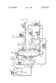
- numeral 10 generally designates a vertical shaft, moving bed reactor having a reforming zone 12 in the upper portion thereof, a cooling zone 16 in the lower portion, and a reduction zone 14 located between the reforming and cooling zones.
- the reactor 10 is suitably heat-insulated and interiorly lined with a refractory material in a manner known in the art.
- the particulate ore which is to be treated is introduced into the reactor 10 through a charging pipe 18.
- the ore charged to the reactor may be in the form of either lumps, pre-formed pellets, or mixtures thereof.
- the reactor Near the bottom of the reforming zone 12, the reactor is provided with an annular plenum chamber 38 which extends around the periphery of the reactor to provide a means whereby a heated gaseous mixture of reducing gas and steam is fed to the reactor.
- the vertical baffle 40 together with the wall of the reactor defines the annular space 38. The ore moves downwardly through the reforming zone wherein it is heated and partially reduced by the upwardly flowing reformed gas.
- the iron ore leaving the reforming zone and entering the reduction zone 14 essentially consists of ferric oxide.
- a second annular plenum chamber 46 similar to plenum chamber 38, through which reformed and treated reducing gas may be fed into the reactor.
- a frusto-conical baffle 48 is also provided which together with the wall of the reactor defines the annular space 46.
- the iron ore moving downwardly through the reduction zone 14 is reduced by the reducing gas passing through the reduction zone.
- the reducing gas leaves the reactor through annular plenum chamber 42.
- the plenum chamber 42 and the frusto-conical baffle 44 are similar to plenum chamber 46 and baffle 48.
- the ore leaving this zone and entering the cooling zone 16 is highly metallized and of low carbon content.
- a frusto-conical baffle 56 is also provided similar to baffles 44 and 48. As the sponge iron moves downwardly through the cooling zone 16, it is cooled by the cooling gas flowing therethrough and leaves through the reactor outlet 58.
- the reducing gas is produced in a coal gasification unit 20 and flows through pipe 22 at a rate controlled by the flow controller 21 and into pipe 24.
- Steam flowing through pipe 28 and controlled by flow controller 26 is mixed with the gas from the coal gasification unit 20 and enters pipe 30.
- the gaseous mixture flows through pipe 30 to a heating coil 34 of a heater 32 wherein it is heated to a temperature in the range of about 300° to 600° C.
- the heated mixture leaves heater 32 through pipe 36 and flows into the plenum chamber 38.
- the gas flowing through plenum chamber 38 enters the reactor near the bottom of the reforming zone 12.
- the heated mixture Upon entering the reforming zone of the reactor, the heated mixture is reformed to obtain a higher and more desirable hydrogen to carbon monoxide ratio.
- the reformed gas flows upwardly through the reforming zone and is removed near the top of the reactor through an outlet connection 60 and pipe 62.
- a portion of the reducing gas produced in the coal gasification unit 20 is injected at low temperature into the cooling zone of the reactor to aid in the cooling of the sponge iron.
- a substantially inert gas from a suitable source may be used as the cooling gas. If all or part of the cooling gas supplied to the cooling zone of the reactor is supplied from the coal gasification system, then a portion of the cooling gas effluent from the cooling zone of the reactor may also be transferred to the reduction loop.
- the reformed gas leaving the reactor through pipe 62 enters a quench cooler 64 into which water is introduced through pipe 66 to cool and effectuate the removal of water therefrom.
- the gas leaves cooler 64 through pipe 68 and flows into pipe 74 which connects with the suction side of pump 76.
- a portion of the gas stream flowing through pipe 68 may flow through pipe 72 to a suitable point of use (not shown).
- Pipe 72 is provided with a back pressure regulator 70 having an adjustable set point so that it may be adjusted to maintain a desired positive and constant pressure in the system to improve the efficiency of reactor 10.
- the gas mixture flowing to pump 76 is discharged through pipe 78 and enters a carbon dioxide absorber 80.
- the carbon dioxide in the stream entering the absorber 80 is removed by a method known in the art by a suitable absorbing medium entering the absorber 80 through pipe 82.
- the gas leaving the absorber through pipe 84 contains only small amounts of carbon dioxide.
- Gas flowing through pipe 84 enters pipe 86 and flows through pipe 88 to the heating coil 92 of heater 90.
- the gas is heated in heater 90 to a temperature in the range of about 850° to 1000° C. and preferably in the range of 850° to 900° C.
- the heated gas leaves heater 90 and flows through pipe 94 into plenum chamber 46 through which it enters the reactor near the bottom of the reduction zone 14.
- the reducing gas passes upwardly through the reduction zone and flows into plenum chamber 42 through which it leaves the reactor.
- the reducing gas stream leaves the reactor through pipe 96 and enters the quench cooler 100 into which water is introduced through pipe 98 to cool and effectuate the removal of water from the reformed gas.
- the gas leaves cooler 100 through pipe 102 and a portion flows through pipe 108 into the suction side of pump 110.
- a portion of the gas flowing through pipe 102 flows through pipe 106 to a suitable point of use.
- Pipe 106 is provided with a back pressure regulator 104 having an adjustable set point so that it may be adjusted to maintain a desired positive and constant pressure in the system to improve the efficiency of reactor 10.
- the gas flows through pump 110 into the discharge pipe 112 and is mixed with the reformed gas leaving the carbon dioxide absorber 80 through pipe 84.
- the combined gas stream then flows through pipes 86 and 88, heater 90 and pipe 94 from which it is fed back into the bottom of the reduction zone 14.
- the inert make-up gas may be supplied from a suitable source (not shown) through pipe 120 at a rate controlled by the flow controller 122.
- the inert gas flowing through pipe 120 then flows through pipe 124 into plenum chamber 54 and into the reactor near the bottom of the cooling zone 16.
- a frusto-conical baffle 56 together with the wall of the reactor defines the annular chamber 54.
- the make-up inert gas flows upwardly through the cooling zone 16 of the reactor and is removed through annular chamber 50.
- the effluent cooling gas flows through pipe 126 into quench cooler 130 into which water is introduced through pipe 128 to cool and effectuate the removal of water in the effluent gas.
- Pipe 134 is also provided with a back pressure regulator 136 having an adjustable set point so that it may be adjusted to maintain a desired positive and constant pressure in the system to improve the efficiency of reactor 10.
- the gas is then discharged by pump 140 through pipe 142 where it may be mixed with make-up inert gas flowing through pipe 120 to enter pipe 123. This gas stream is then recycled back through pipe 124 and plenum chamber 54 into the cooling zone 16 of the reactor. Alternatively, a portion of the gas flowing through pipe 142 is directed to the reducing loop via pipe 150 at a rate controlled by flow controller 152 and mixed with the reformed and treated gas flowing through pipe 86.
- a portion of the gas from the coal gasification unit 20 may be caused to flow through pipe 144 at a rate controlled by flow controller 146.
- the gas then flows through pipe 124 into plenum chamber 54 and into the bottom of the cooling zone 16.
Landscapes
- Engineering & Computer Science (AREA)
- Chemical & Material Sciences (AREA)
- Manufacturing & Machinery (AREA)
- Materials Engineering (AREA)
- Metallurgy (AREA)
- Organic Chemistry (AREA)
- Manufacture Of Iron (AREA)
- Industrial Gases (AREA)
Abstract
A method for the gaseous reduction of particulate ores to metals in a moving bed, vertical shaft reactor using a reducing gas externally supplied from a solid or liquid fossil fuel gasification unit. The reducing gas is reformed in a reforming zone located within the reactor and treated prior to injection into the reduction zone of the reactor. A portion of the reducing gas produced in a coal gasification unit may be used to cool the metal in the cooling zone of the reactor.
Description
This invention relates generally to a method for the gaseous reduction of particulate ores to metals in particulate form in a moving bed, vertical shaft reactor, and more particularly, to a method for the reduction of the ore and the cooling of the resulting metal particles using a reducing gas externally supplied from a solid or liquid fossil fuel gasification unit. This invention is particularly suitable to the reduction of iron ore to sponge iron and is illustratively described with particular reference thereto.
For purposes of describing the present invention the terms "reforming," "reforming zone," etc., specifically refer to chemical reactions whereby the H2 to CO ratio of the reducing gas supplied to the moving bed, vertical shaft reactor is increased.
In general, the production of sponge iron in a typical vertical shaft, moving bed reactor involves two principal steps, namely, reduction of the ore with a suitable hot reducing gas in a reduction zone of the reactor and then subsequent cooling of the resulting sponge iron with a gaseous coolant in a cooling zone of the reactor. The reducing gas is typically a gas largely composed of carbon monoxide and hydrogen injected into the reactor at temperatures in the range of 850° C. to 1100° C., preferably 900° C. to 1000° C. The hot reducing gas may be introduced into the reactor at the bottom of the reduction zone and passed upwardly through the reactor to flow counter-currently to the downwardly moving ore, or alternatively, the hot reducing gas may be introduced at the top of the reduction zone and caused to flow co-currently with the downwardly moving ore. It is well known in the art to cool the sponge iron by injecting a cooling gas at relatively low temperature into the cooling zone of the reactor and passing the cooling gas upwardly through the reactor whereby the cooling gas temperature is increased and the temperature of the sponge iron is reduced.
In previously proposed processes, the reducing gas used in the direct reduction of iron ores has been derived from a number of sources, e.g., the catalytic reforming of hydrocarbons and steam. Systems using natural gas and steam to generate a reducing gas require the use of catalytic reforming units. In prior processes where solid or liquid fuels are used to generate the reducing gas as opposed to those processes which utilize natural gas, additional equipment has been required to enrich the gas so that it may be effectively used for reduction purposes.
It is accordingly an object of the present invention to provide a metal ore reduction process in which a metal ore, e.g., iron ore, is reduced to sponge metal, e.g., sponge iron, by a reducing gas produced by the gasification of solid or liquid fossil fuels which is reformed within the reactor to increase its reducing efficiency.
It is another object of the invention to provide a reducing gas from a gasification unit which is reformed within the reactor and treated prior to being used to reduce the metal ore.
It is still a further object of the invention to provide a reducing gas with a desirable hydrogen to carbon monoxide ratio which substantially increases the reduction reaction rate of the metal ore and thereby decreases the residence time of the ore through the reactor.
Other objects of the invention will be in part obvious and in part pointed out hereafter.
The objects and advantages of the present invention may be generally achieved by providing a reforming zone within the reactor to reform a reducing gas produced in a suitable gasification unit. Since the gas diffusion rate into the ore particles is essentially temperature independent and depends primarily upon the concentration of hydrogen present in the reducing gas, the reducing gas should desirably have a relatively high hydrogen content. In accordance with the invention, a reducing gas which may be prepared by the gasification of coal with oxygen and water vapor is mixed with steam and heated. The heated gas mixture is injected into the reactor and reformed in a reforming zone located in the upper portion of the reactor to produce a higher and more desirable H2 to CO ratio. In the reforming zone the H2 to CO ratio which is typically in the range of about 0.5:1 to 1:1 is raised to a suitable value for iron ore reduction, i.e., in the range of about 2.5:1 to 5:1 by means of the water-gas shift reaction:
CO+H.sub.2 O→H.sub.2 +CO.sub.2
The iron-bearing material in the reactor acts as a particularly effective catalyst for this reaction. The composition of a typical effluent gas from a liquid fossil fuel gasifier unit as reported in S. C. Singer, Jr. and L. W. Ternhaar "Reducing Gases by Partial Oxidation of Hydrocarbons," Chemical Engineering Progress, Vol. 57, No. 7, (July 1961), pp. 68-74, is as follows:
______________________________________
              % Volume, Dry Basis
______________________________________
H.sub.2         46.1
CO              46.9
CO.sub.2        4.3
N.sub.2         1.4
CH.sub.4        0.4
H.sub.2 O       0.9
                100.0
______________________________________
The composition of a typical effluent gas from a solid fuel gasifier unit as reported in the "Institute of Gas Technology Hydrogen Production From Coal Interim Report Project 8963" presented at N.A.S.A. Marshall Space Flight Center, Alabama, Apr. 24, 1975, and distributed by N.T.I.S. N75-24113, is as follows:
______________________________________
              % Volume, Dry Basis
______________________________________
H.sub.2         30.4
CO              58.3
CO.sub.2        10.0
N.sub.2         1.0
CH.sub.4        0.0
H.sub.2 O       0.3
                100.0
______________________________________
This higher H2 to CO ratio is desirable because the reduction reaction rate using hydrogen is higher than that of carbon monoxide thereby decreasing the residence time of the ore in the reactor. In addition, since a higher amount of CO tends to deposit elemental carbon on the ore, the increased proportion of hydrogen will minimize such deposition. The change in the CO content also allows for better control of carburization.
The reformed gas produced in the upper portion of the reactor is removed from the reforming zone of the reactor to an external loop wherein it is cooled, compressed and caused to flow through an absorption tower to remove carbon dioxide. The reformed and treated gas is then transferred to a heater in which it is heated to an elevated temperature in the range of about 750° C. to 1000° C. after which it is injected into the reduction zone as a reducing gas. The reducing gas passes through the reduction zone of the reactor in contact with the metal ore thereby effectuating a reduction of the ore after which it is removed from the reduction zone and cooled to remove water therefrom. The cooled reducing gas is then combined with the reformed and treated gas stream being recirculated to the reduction zone of the reactor.
While it is known to use a reducing gas produced in a coal gasification system in the direct reduction of metal ores, reforming the gas within the reactor to increase the H2 to CO ratio has not been previously disclosed. Similarly, the method of reforming the reducing gas supplied from a solid or liquid fossil fuel gasification unit within the reactor followed by treating such gas prior to injection into the reduction zone of the reactor has heretofore been unknown in the prior art. The invention provides a method whereby a reducing gas produced in a fuel gasification system can be more efficiently and economically utilized for the reduction of metal ores. Additionally, through this invention the reducing gas is reformed within the reactor thereby eliminating the need for a separate reforming unit or reactor resulting in an energy and capital cost saving.
The many objects and advantages of the present invention can best be understood and appreciated by reference to the accompanying drawing which illustrates a sponge iron production system incorporating several modifications of the invention and comprising a vertical shaft moving bed reactor with a reforming zone located in the upper portion thereof. For purposes of this description the reducing gas is produced in a coal gasification unit.
Referring to the drawing, numeral 10 generally designates a vertical shaft, moving bed reactor having a reforming zone 12 in the upper portion thereof, a cooling zone 16 in the lower portion, and a reduction zone 14 located between the reforming and cooling zones. The reactor 10 is suitably heat-insulated and interiorly lined with a refractory material in a manner known in the art.
The particulate ore which is to be treated is introduced into the reactor 10 through a charging pipe 18. The ore charged to the reactor may be in the form of either lumps, pre-formed pellets, or mixtures thereof. Near the bottom of the reforming zone 12, the reactor is provided with an annular plenum chamber 38 which extends around the periphery of the reactor to provide a means whereby a heated gaseous mixture of reducing gas and steam is fed to the reactor. The vertical baffle 40 together with the wall of the reactor defines the annular space 38. The ore moves downwardly through the reforming zone wherein it is heated and partially reduced by the upwardly flowing reformed gas.
The iron ore leaving the reforming zone and entering the reduction zone 14 essentially consists of ferric oxide. Near the bottom of the reduction zone 14 there is a second annular plenum chamber 46, similar to plenum chamber 38, through which reformed and treated reducing gas may be fed into the reactor. A frusto-conical baffle 48 is also provided which together with the wall of the reactor defines the annular space 46.
The iron ore moving downwardly through the reduction zone 14 is reduced by the reducing gas passing through the reduction zone. The reducing gas leaves the reactor through annular plenum chamber 42. The plenum chamber 42 and the frusto-conical baffle 44 are similar to plenum chamber 46 and baffle 48.
As a result of the reduction achieved in the reduction zone, the ore leaving this zone and entering the cooling zone 16 is highly metallized and of low carbon content. Near the bottom of the cooling zone 16 there is another annular plenum chamber 54 through which substantially inert cooling gas can be fed into the reactor if desired. A frusto-conical baffle 56 is also provided similar to baffles 44 and 48. As the sponge iron moves downwardly through the cooling zone 16, it is cooled by the cooling gas flowing therethrough and leaves through the reactor outlet 58.
Turning now to the gas flows in the present system, the reducing gas is produced in a coal gasification unit 20 and flows through pipe 22 at a rate controlled by the flow controller 21 and into pipe 24. Steam flowing through pipe 28 and controlled by flow controller 26 is mixed with the gas from the coal gasification unit 20 and enters pipe 30. The gaseous mixture flows through pipe 30 to a heating coil 34 of a heater 32 wherein it is heated to a temperature in the range of about 300° to 600° C. The heated mixture leaves heater 32 through pipe 36 and flows into the plenum chamber 38. The gas flowing through plenum chamber 38 enters the reactor near the bottom of the reforming zone 12. Upon entering the reforming zone of the reactor, the heated mixture is reformed to obtain a higher and more desirable hydrogen to carbon monoxide ratio. The reformed gas flows upwardly through the reforming zone and is removed near the top of the reactor through an outlet connection 60 and pipe 62.
In one modification of the invention a portion of the reducing gas produced in the coal gasification unit 20 is injected at low temperature into the cooling zone of the reactor to aid in the cooling of the sponge iron. However, if a low carbon content in the sponge iron is desired, a substantially inert gas from a suitable source may be used as the cooling gas. If all or part of the cooling gas supplied to the cooling zone of the reactor is supplied from the coal gasification system, then a portion of the cooling gas effluent from the cooling zone of the reactor may also be transferred to the reduction loop.
The reformed gas leaving the reactor through pipe 62 enters a quench cooler 64 into which water is introduced through pipe 66 to cool and effectuate the removal of water therefrom. The gas leaves cooler 64 through pipe 68 and flows into pipe 74 which connects with the suction side of pump 76. A portion of the gas stream flowing through pipe 68 may flow through pipe 72 to a suitable point of use (not shown). Pipe 72 is provided with a back pressure regulator 70 having an adjustable set point so that it may be adjusted to maintain a desired positive and constant pressure in the system to improve the efficiency of reactor 10.
The gas mixture flowing to pump 76 is discharged through pipe 78 and enters a carbon dioxide absorber 80. The carbon dioxide in the stream entering the absorber 80 is removed by a method known in the art by a suitable absorbing medium entering the absorber 80 through pipe 82. The gas leaving the absorber through pipe 84 contains only small amounts of carbon dioxide. Gas flowing through pipe 84 enters pipe 86 and flows through pipe 88 to the heating coil 92 of heater 90. The gas is heated in heater 90 to a temperature in the range of about 850° to 1000° C. and preferably in the range of 850° to 900° C. The heated gas leaves heater 90 and flows through pipe 94 into plenum chamber 46 through which it enters the reactor near the bottom of the reduction zone 14.
The reducing gas passes upwardly through the reduction zone and flows into plenum chamber 42 through which it leaves the reactor. The reducing gas stream leaves the reactor through pipe 96 and enters the quench cooler 100 into which water is introduced through pipe 98 to cool and effectuate the removal of water from the reformed gas. The gas leaves cooler 100 through pipe 102 and a portion flows through pipe 108 into the suction side of pump 110. A portion of the gas flowing through pipe 102 flows through pipe 106 to a suitable point of use. Pipe 106 is provided with a back pressure regulator 104 having an adjustable set point so that it may be adjusted to maintain a desired positive and constant pressure in the system to improve the efficiency of reactor 10.
The gas flows through pump 110 into the discharge pipe 112 and is mixed with the reformed gas leaving the carbon dioxide absorber 80 through pipe 84. The combined gas stream then flows through pipes 86 and 88, heater 90 and pipe 94 from which it is fed back into the bottom of the reduction zone 14.
The inert make-up gas, preferably nitrogen, may be supplied from a suitable source (not shown) through pipe 120 at a rate controlled by the flow controller 122. The inert gas flowing through pipe 120 then flows through pipe 124 into plenum chamber 54 and into the reactor near the bottom of the cooling zone 16. A frusto-conical baffle 56 together with the wall of the reactor defines the annular chamber 54. The make-up inert gas flows upwardly through the cooling zone 16 of the reactor and is removed through annular chamber 50. The effluent cooling gas flows through pipe 126 into quench cooler 130 into which water is introduced through pipe 128 to cool and effectuate the removal of water in the effluent gas. The gas leaves cooler 130 through pipe 132 and flows into pipe 138 which connects with the suction side of pump 140. A portion of the gas stream flowing through pipe 132 may flow through pipe 134 to a suitable point of use not shown. Pipe 134 is also provided with a back pressure regulator 136 having an adjustable set point so that it may be adjusted to maintain a desired positive and constant pressure in the system to improve the efficiency of reactor 10.
The gas is then discharged by pump 140 through pipe 142 where it may be mixed with make-up inert gas flowing through pipe 120 to enter pipe 123. This gas stream is then recycled back through pipe 124 and plenum chamber 54 into the cooling zone 16 of the reactor. Alternatively, a portion of the gas flowing through pipe 142 is directed to the reducing loop via pipe 150 at a rate controlled by flow controller 152 and mixed with the reformed and treated gas flowing through pipe 86.
It is to be understood that the foregoing description is intended to be illustrative only and that the embodiments described can be modified in various ways within the scope of the invention. For example, a portion of the gas from the coal gasification unit 20 may be caused to flow through pipe 144 at a rate controlled by flow controller 146. The gas then flows through pipe 124 into plenum chamber 54 and into the bottom of the cooling zone 16.
The terms and expressions which have been employed are used as terms of description and not of limitation, and there is no intention in the use of such terms and expressions of excluding any equivalents of the features shown and described or portions thereof, it being recognized that various modifications are possible within the scope of the invention.
Claims (8)
1. A method for reducing a particulate iron ore to sponge iron in a vertical shaft, moving bed reactor having a reforming zone in the upper portion thereof to which the iron ore is fed, a cooling zone in the lower portion thereof for cooling the sponge iron, and a reducing zone between the reforming and cooling zones for reducing the iron ore to sponge iron which comprises preparing a reducing gas by the gasification of solid or liquid fossil fuels with oxygen and water vapor, mixing the reducing gas with steam, heating the resulting mixture to a temperature in the range of 300° to 600° C., passing the heated mixture through the reforming zone in contact with iron-bearing material therein to reform the gaseous mixture to increase the hydrogen to carbon monoxide ratio thereof, removing the reformed gas from the reforming zone and removing a portion of the carbon dioxide content and using the reformed gas to reduce iron ore in the reduction zone of said reactor.
2. A method according to claim 1 wherein the reduced ore in the cooling zone is cooled by circulating an inert gas therethrough wherein said inert gas is fed to the cooling zone and caused to flow upwardly through said cooling zone of the reactor.
3. A method according to claim 2 wherein the inert gas consists essentially of nitrogen.
4. A method according to claim 1 wherein a portion of the reducing gas at low temperature is fed to the cooling zone of the reactor and passed upwardly through the cooling zone to cool the reduced ore.
5. A method for reducing a particulate iron ore to sponge iron in a vertical shaft, moving bed reactor having a reforming zone in the upper portion thereof, a cooling zone in the lower portion thereof for cooling the sponge iron, and a reduction zone between the reforming and cooling zones for reducing the iron ore to sponge iron which comprises preparing a first stream of reducing gas prepared by the gasification of solid or liquid fossil fuels with oxygen and water vapor, mixing the reducing gas with steam, heating the resulting mixture to a temperature in the range of 300° to 600° C., feeding the heated mixture as a second stream to the reforming zone at a point near one end thereof, passing the gaseous mixture through the reforming zone in contact with iron-bearing material therein to reform the gaseous mixture to increase the hydrogen to carbon monoxide ratio thereof, removing from a point near the other end of the reforming zone the reformed gas as a third stream, cooling the third stream to remove water therefrom to form a fourth stream of essentially hydrogen, carbon monoxide and carbon dioxide, removing at least a portion of the carbon dioxide content of the cooled fourth stream to form a reconditioned reducing gas as a fifth gas stream, heating the fifth stream, and using the reformed and reconditioned gas to reduce iron ore in the reduction zone of the reactor.
6. A method according to claim 5 wherein the reduced ore in the cooling zone is cooled by circulating an inert gas therethrough wherein said inert gas is fed to the cooling zone and caused to flow upwardly through said cooling zone of the reactor.
7. A method according to claim 5 wherein the inert gas consists essentially of nitrogen.
8. A method according to claim 5 wherein a portion of the first stream is fed to the cooling zone of the reactor and passed upwardly through the cooling zone to cool the reduced ore.
Priority Applications (19)
| Application Number | Priority Date | Filing Date | Title |
|---|---|---|---|
| US06/089,902 US4246024A (en) | 1979-10-31 | 1979-10-31 | Method for the gaseous reduction of metal ores using reducing gas produced by gasification of solid or liquid fossil fuels |
| ZA00805062A ZA805062B (en) | 1979-10-31 | 1980-08-18 | Method for the gaseous reduction of metal ores using reducing gas produced by gasification of solid or liquid fossil fuels |
| AU61641/80A AU538947B2 (en) | 1979-10-31 | 1980-08-21 | Gaseous reduction of metal ores using reducing gas produced by gasification of solid or liquid fossil fuels |
| AR282424A AR225934A1 (en) | 1979-10-31 | 1980-09-05 | METHOD FOR PRODUCING SPONGE IRON BY REDUCING A PARTICULAR IRON MINERAL IN A VERTICAL MOBILE BED REACTOR |
| ZM77/80A ZM7780A1 (en) | 1979-10-31 | 1980-09-10 | Method for the gaseous reduction of metal ores using reducing gas produced by gasification of solid or liquid fossil fuels |
| BR8005801A BR8005801A (en) | 1979-10-31 | 1980-09-11 | PROCESS TO REDUCE AN IRON ORE IN PARTICULATES FOR SPONGE IRON IN A MOVING BED REACTOR OF VERTICAL CUBA |
| IT24695/80A IT1141055B (en) | 1979-10-31 | 1980-09-16 | PROCEDURE FOR THE GASEOUS REDUCTION OF METAL MINERALS USING A REDUCING GAS PRODUCED BY GASIFICATION OF SOLID OR LIQUID FOSSIL FUELS |
| IN1128/CAL/80A IN153109B (en) | 1979-10-31 | 1980-10-03 | |
| DE3037865A DE3037865C2 (en) | 1979-10-31 | 1980-10-07 | Process for reducing a finely divided iron ore to sponge iron |
| FR8022157A FR2468650A1 (en) | 1979-10-31 | 1980-10-16 | PROCESS FOR THE GAS REDUCTION OF METALLIC ORES, IN PARTICULAR IRON ORE, USING REDUCING GAS FORMED BY GASIFYING FOSSIL, SOLID OR LIQUID FUELS |
| JP55148105A JPS5825727B2 (en) | 1979-10-31 | 1980-10-22 | Method for reducing granular iron ore to sponge iron particles |
| CA000363396A CA1153559A (en) | 1979-10-31 | 1980-10-28 | Method for the gaseous reduction of metal ores using reducing gas produced by gasification of solid or liquid fossil fuels |
| DD224782A DD153894A5 (en) | 1979-10-31 | 1980-10-28 | METHOD FOR GAS REDUCTION OF PARTICULAR ORIGINS |
| GB8034792A GB2065709B (en) | 1979-10-31 | 1980-10-29 | Gaseous reduction of metal ores using reducing gas produced by gasification of solid or liquid fossil fuels |
| SE8007603A SE448552B (en) | 1979-10-31 | 1980-10-29 | SEE THE REDUCTION OF FINE CORN IRON ORE TO IRON SPAM IN REACTOR WITH STANDING SHAKT |
| BE0/202625A BE885920A (en) | 1979-10-31 | 1980-10-29 | PROCESS FOR THE GASEOUS REDUCTION OF METAL ORES USING REDUCING GAS FORMED BY GASIFICATION OF FOSSIL FUELS |
| ES496420A ES496420A0 (en) | 1979-10-31 | 1980-10-30 | A METHOD TO REDUCE A MINERAL OF PARTICULAR IRON TO SPONGE IRON IN A VERTICAL CUBA REACTOR OF MOVING BED |
| MX184544A MX154127A (en) | 1979-10-31 | 1980-10-30 | IMPROVED METHOD TO REDUCE A MINERAL OF PARTICULAR IRON TO SPONGE IRON, THROUGH A REDUCING GAS IN A CUBA OVEN |
| SU802999796A SU1128843A3 (en) | 1979-10-31 | 1980-10-30 | Method of reduction of iron ore to sponge iron in shaft reactor |
Applications Claiming Priority (1)
| Application Number | Priority Date | Filing Date | Title |
|---|---|---|---|
| US06/089,902 US4246024A (en) | 1979-10-31 | 1979-10-31 | Method for the gaseous reduction of metal ores using reducing gas produced by gasification of solid or liquid fossil fuels |
Publications (1)
| Publication Number | Publication Date |
|---|---|
| US4246024A true US4246024A (en) | 1981-01-20 |
Family
ID=22220149
Family Applications (1)
| Application Number | Title | Priority Date | Filing Date |
|---|---|---|---|
| US06/089,902 Expired - Lifetime US4246024A (en) | 1979-10-31 | 1979-10-31 | Method for the gaseous reduction of metal ores using reducing gas produced by gasification of solid or liquid fossil fuels |
Country Status (19)
| Country | Link |
|---|---|
| US (1) | US4246024A (en) |
| JP (1) | JPS5825727B2 (en) |
| AR (1) | AR225934A1 (en) |
| AU (1) | AU538947B2 (en) |
| BE (1) | BE885920A (en) |
| BR (1) | BR8005801A (en) |
| CA (1) | CA1153559A (en) |
| DD (1) | DD153894A5 (en) |
| DE (1) | DE3037865C2 (en) |
| ES (1) | ES496420A0 (en) |
| FR (1) | FR2468650A1 (en) |
| GB (1) | GB2065709B (en) |
| IN (1) | IN153109B (en) |
| IT (1) | IT1141055B (en) |
| MX (1) | MX154127A (en) |
| SE (1) | SE448552B (en) |
| SU (1) | SU1128843A3 (en) |
| ZA (1) | ZA805062B (en) |
| ZM (1) | ZM7780A1 (en) |
Cited By (15)
| Publication number | Priority date | Publication date | Assignee | Title |
|---|---|---|---|---|
| US4325731A (en) * | 1979-03-24 | 1982-04-20 | Metallgesellschaft Aktiengesellschaft | Process of producing reducing gas from solid fuels |
| EP0128347A2 (en) * | 1983-05-16 | 1984-12-19 | HYLSA, S.A. de C.V. | Method for reducing iron ore |
| FR2570082A1 (en) * | 1984-09-10 | 1986-03-14 | Midrex Int Bv | METHOD FOR REDUCING METAL OXIDE USING REDUCING GASES FROM REFORMING PENTANE OR SUPERIOR HYDROCARBONS |
| WO2001032940A1 (en) * | 1999-11-05 | 2001-05-10 | Crg Kohlenstoffrecycling Ges.Mbh | Method and devices used in the production of iron for increasing output and reducing fuel consumption |
| US20050151307A1 (en) * | 2003-09-30 | 2005-07-14 | Ricardo Viramontes-Brown | Method and apparatus for producing molten iron |
| WO2007122509A2 (en) * | 2006-04-24 | 2007-11-01 | Hyl Technologies, S.A. De C.V. | Method and apparatus for producing direct reduced iron |
| WO2008146112A1 (en) * | 2007-05-25 | 2008-12-04 | Hyl Technologies, S.A. De C.V | Method and apparatus for the direct reduction of iron ores utilizing syngas |
| CN110438278A (en) * | 2019-09-11 | 2019-11-12 | 武汉科思瑞迪科技有限公司 | A kind of Shaft Furnace Direct Reduction Process of gas base and the combination of coal base phase |
| CN110453027A (en) * | 2019-09-11 | 2019-11-15 | 武汉科思瑞迪科技有限公司 | A kind of Shaft Furnace Direct Reduction Process of gas base and the combination of coal base phase |
| WO2021094195A1 (en) * | 2019-11-15 | 2021-05-20 | Thyssenkrupp Steel Europe Ag | Method for the direct reduction of iron ore |
| WO2022109245A1 (en) * | 2020-11-20 | 2022-05-27 | Carbon Technology Holdings, LLC | Biomass pyrolysis integrated with bio-reduction of metal ores, hydrogen production, and/or activated- carbon production |
| US11674101B2 (en) | 2011-04-15 | 2023-06-13 | Carbon Technology Holdings, LLC | Process for producing high-carbon biogenic reagents |
| US11753698B2 (en) | 2020-09-25 | 2023-09-12 | Carbon Technology Holdings, LLC | Bio-reduction of metal ores integrated with biomass pyrolysis |
| US11932814B2 (en) | 2021-04-27 | 2024-03-19 | Carbon Technology Holdings, LLC | Biocarbon blends with optimized fixed carbon content, and methods for making and using the same |
| US11987763B2 (en) | 2021-07-09 | 2024-05-21 | Carbon Technology Holdings, LLC | Processes for producing biocarbon pellets with high fixed-carbon content and optimized reactivity, and biocarbon pellets obtained therefrom |
Families Citing this family (8)
| Publication number | Priority date | Publication date | Assignee | Title |
|---|---|---|---|---|
| US4381939A (en) * | 1981-01-29 | 1983-05-03 | Midrex Corporation | Method for selective reduction of metallic oxides |
| DE3317701C2 (en) * | 1983-05-16 | 1986-08-07 | Hylsa S.A., Monterrey, N.L. | A method of operating a vertical shaft moving bed reduction reactor for reducing iron ore to sponge iron |
| DE3422186A1 (en) * | 1984-06-12 | 1985-12-12 | Korf Engineering GmbH, 4000 Düsseldorf | Process for the direct reduction of iron ore or iron oxide pellets to give sponge iron, and system for carrying out this process |
| AT382166B (en) * | 1985-05-13 | 1987-01-26 | Voest Alpine Ag | METHOD FOR DIRECTLY REDUCING PARTICULAR IRON-OXIDATING MATERIAL |
| CA1336359C (en) * | 1987-11-02 | 1995-07-25 | Corporacion Venezolana De Guayana (Cvg) | Method and apparatus for the direct reduction of iron |
| USD435707S (en) | 1999-09-07 | 2000-12-26 | Amptek Company Limited | Vacuum cleaner |
| KR101376138B1 (en) | 2012-12-27 | 2014-03-19 | 주식회사 포스코 | Apparatus for manufacturing molten iron and method for manufacturing thereof |
| DE102021122351A1 (en) * | 2021-08-30 | 2023-03-02 | Thyssenkrupp Steel Europe Ag | Process for the production of an iron melt |
Citations (7)
| Publication number | Priority date | Publication date | Assignee | Title |
|---|---|---|---|---|
| US1112007A (en) * | 1912-06-13 | 1914-09-29 | Karl Albert Fredrik Hiorth | Process of producing iron and steel directly from the ore |
| US3853538A (en) * | 1973-07-20 | 1974-12-10 | Steel Corp | Use of reducing gas by coal gasification for direct iron ore reduction |
| US3905806A (en) * | 1973-02-20 | 1975-09-16 | Armco Steel Corp | Method for the direct reduction of iron ores |
| US4019724A (en) * | 1973-02-20 | 1977-04-26 | Armco Steel Corporation | Apparatus for the direct reduction of iron ores |
| US4046555A (en) * | 1974-08-13 | 1977-09-06 | Thyssen Purofe Gmbh | Method of direct reduction of iron ore |
| US4108636A (en) * | 1974-08-13 | 1978-08-22 | Thyssen Purofer Gmbh | Method of the direct reduction of iron ore |
| US4150972A (en) * | 1977-11-17 | 1979-04-24 | Fierro Esponja, S.A. | Controlling carburization in the reduction of iron ore to sponge iron |
Family Cites Families (5)
| Publication number | Priority date | Publication date | Assignee | Title |
|---|---|---|---|---|
| US3827879A (en) * | 1973-02-22 | 1974-08-06 | Fierro Esponja | Method for the gaseous reduction of metal ores |
| DE2431537A1 (en) * | 1974-07-01 | 1976-01-22 | Metallgesellschaft Ag | Direct redn of iron ore to sponge iron in shaft furnace - with redn. gas obtd from high-pressure gasification of coal |
| SE387366C (en) * | 1974-12-12 | 1980-03-27 | Stora Kopparbergs Bergslags Ab | SET FOR REDUCING FINALLY DISTRIBUTED METAL OXID CONTAINING MATERIAL |
| JPS52155116A (en) * | 1976-06-18 | 1977-12-23 | Kobe Steel Ltd | Reduced iron preparation using hydrocarbon gas as reducing agent |
| US4160663A (en) * | 1978-02-21 | 1979-07-10 | Jack Hsieh | Method for the direct reduction of iron ore |
-
1979
- 1979-10-31 US US06/089,902 patent/US4246024A/en not_active Expired - Lifetime
-
1980
- 1980-08-18 ZA ZA00805062A patent/ZA805062B/en unknown
- 1980-08-21 AU AU61641/80A patent/AU538947B2/en not_active Ceased
- 1980-09-05 AR AR282424A patent/AR225934A1/en active
- 1980-09-10 ZM ZM77/80A patent/ZM7780A1/en unknown
- 1980-09-11 BR BR8005801A patent/BR8005801A/en unknown
- 1980-09-16 IT IT24695/80A patent/IT1141055B/en active
- 1980-10-03 IN IN1128/CAL/80A patent/IN153109B/en unknown
- 1980-10-07 DE DE3037865A patent/DE3037865C2/en not_active Expired
- 1980-10-16 FR FR8022157A patent/FR2468650A1/en active Granted
- 1980-10-22 JP JP55148105A patent/JPS5825727B2/en not_active Expired
- 1980-10-28 CA CA000363396A patent/CA1153559A/en not_active Expired
- 1980-10-28 DD DD224782A patent/DD153894A5/en unknown
- 1980-10-29 BE BE0/202625A patent/BE885920A/en not_active IP Right Cessation
- 1980-10-29 GB GB8034792A patent/GB2065709B/en not_active Expired
- 1980-10-29 SE SE8007603A patent/SE448552B/en not_active IP Right Cessation
- 1980-10-30 MX MX184544A patent/MX154127A/en unknown
- 1980-10-30 ES ES496420A patent/ES496420A0/en active Granted
- 1980-10-30 SU SU802999796A patent/SU1128843A3/en active
Patent Citations (7)
| Publication number | Priority date | Publication date | Assignee | Title |
|---|---|---|---|---|
| US1112007A (en) * | 1912-06-13 | 1914-09-29 | Karl Albert Fredrik Hiorth | Process of producing iron and steel directly from the ore |
| US3905806A (en) * | 1973-02-20 | 1975-09-16 | Armco Steel Corp | Method for the direct reduction of iron ores |
| US4019724A (en) * | 1973-02-20 | 1977-04-26 | Armco Steel Corporation | Apparatus for the direct reduction of iron ores |
| US3853538A (en) * | 1973-07-20 | 1974-12-10 | Steel Corp | Use of reducing gas by coal gasification for direct iron ore reduction |
| US4046555A (en) * | 1974-08-13 | 1977-09-06 | Thyssen Purofe Gmbh | Method of direct reduction of iron ore |
| US4108636A (en) * | 1974-08-13 | 1978-08-22 | Thyssen Purofer Gmbh | Method of the direct reduction of iron ore |
| US4150972A (en) * | 1977-11-17 | 1979-04-24 | Fierro Esponja, S.A. | Controlling carburization in the reduction of iron ore to sponge iron |
Cited By (23)
| Publication number | Priority date | Publication date | Assignee | Title |
|---|---|---|---|---|
| US4325731A (en) * | 1979-03-24 | 1982-04-20 | Metallgesellschaft Aktiengesellschaft | Process of producing reducing gas from solid fuels |
| EP0128347A2 (en) * | 1983-05-16 | 1984-12-19 | HYLSA, S.A. de C.V. | Method for reducing iron ore |
| EP0128347A3 (en) * | 1983-05-16 | 1985-04-24 | Hylsa, S.A. | Method for reducing iron ore |
| US4528030A (en) * | 1983-05-16 | 1985-07-09 | Hylsa, S.A. | Method of reducing iron ore |
| FR2570082A1 (en) * | 1984-09-10 | 1986-03-14 | Midrex Int Bv | METHOD FOR REDUCING METAL OXIDE USING REDUCING GASES FROM REFORMING PENTANE OR SUPERIOR HYDROCARBONS |
| WO2001032940A1 (en) * | 1999-11-05 | 2001-05-10 | Crg Kohlenstoffrecycling Ges.Mbh | Method and devices used in the production of iron for increasing output and reducing fuel consumption |
| US20050151307A1 (en) * | 2003-09-30 | 2005-07-14 | Ricardo Viramontes-Brown | Method and apparatus for producing molten iron |
| WO2007122509A2 (en) * | 2006-04-24 | 2007-11-01 | Hyl Technologies, S.A. De C.V. | Method and apparatus for producing direct reduced iron |
| WO2007122509A3 (en) * | 2006-04-24 | 2008-04-17 | Hyl Technologies Sa De Cv | Method and apparatus for producing direct reduced iron |
| WO2008146112A1 (en) * | 2007-05-25 | 2008-12-04 | Hyl Technologies, S.A. De C.V | Method and apparatus for the direct reduction of iron ores utilizing syngas |
| US11674101B2 (en) | 2011-04-15 | 2023-06-13 | Carbon Technology Holdings, LLC | Process for producing high-carbon biogenic reagents |
| US11879107B2 (en) | 2011-04-15 | 2024-01-23 | Carbon Technology Holdings, LLC | High-carbon biogenic reagents and uses thereof |
| US11891582B2 (en) | 2011-04-15 | 2024-02-06 | Carbon Technology Holdings, LLC | High-carbon biogenic reagents and uses thereof |
| US11959038B2 (en) | 2011-04-15 | 2024-04-16 | Carbon Technology Holdings, LLC | High-carbon biogenic reagents and uses thereof |
| US11965139B2 (en) | 2011-04-15 | 2024-04-23 | Carbon Technology Holdings, LLC | Systems and apparatus for production of high-carbon biogenic reagents |
| CN110453027A (en) * | 2019-09-11 | 2019-11-15 | 武汉科思瑞迪科技有限公司 | A kind of Shaft Furnace Direct Reduction Process of gas base and the combination of coal base phase |
| CN110438278A (en) * | 2019-09-11 | 2019-11-12 | 武汉科思瑞迪科技有限公司 | A kind of Shaft Furnace Direct Reduction Process of gas base and the combination of coal base phase |
| WO2021094195A1 (en) * | 2019-11-15 | 2021-05-20 | Thyssenkrupp Steel Europe Ag | Method for the direct reduction of iron ore |
| CN114729409A (en) * | 2019-11-15 | 2022-07-08 | 蒂森克虏伯钢铁欧洲股份公司 | Method for direct reduction of iron ore |
| US11753698B2 (en) | 2020-09-25 | 2023-09-12 | Carbon Technology Holdings, LLC | Bio-reduction of metal ores integrated with biomass pyrolysis |
| WO2022109245A1 (en) * | 2020-11-20 | 2022-05-27 | Carbon Technology Holdings, LLC | Biomass pyrolysis integrated with bio-reduction of metal ores, hydrogen production, and/or activated- carbon production |
| US11932814B2 (en) | 2021-04-27 | 2024-03-19 | Carbon Technology Holdings, LLC | Biocarbon blends with optimized fixed carbon content, and methods for making and using the same |
| US11987763B2 (en) | 2021-07-09 | 2024-05-21 | Carbon Technology Holdings, LLC | Processes for producing biocarbon pellets with high fixed-carbon content and optimized reactivity, and biocarbon pellets obtained therefrom |
Also Published As
| Publication number | Publication date |
|---|---|
| FR2468650B1 (en) | 1984-02-17 |
| DD153894A5 (en) | 1982-02-10 |
| ZA805062B (en) | 1981-08-26 |
| ES8205865A1 (en) | 1982-06-16 |
| BR8005801A (en) | 1981-05-19 |
| IT8024695A0 (en) | 1980-09-16 |
| MX154127A (en) | 1987-05-21 |
| SE448552B (en) | 1987-03-02 |
| GB2065709A (en) | 1981-07-01 |
| DE3037865A1 (en) | 1981-05-27 |
| SE8007603L (en) | 1981-05-01 |
| ES496420A0 (en) | 1982-06-16 |
| CA1153559A (en) | 1983-09-13 |
| AU538947B2 (en) | 1984-09-06 |
| AR225934A1 (en) | 1982-05-14 |
| DE3037865C2 (en) | 1985-08-29 |
| GB2065709B (en) | 1983-09-21 |
| ZM7780A1 (en) | 1981-09-21 |
| SU1128843A3 (en) | 1984-12-07 |
| IN153109B (en) | 1984-06-02 |
| IT1141055B (en) | 1986-10-01 |
| FR2468650A1 (en) | 1981-05-08 |
| AU6164180A (en) | 1981-05-07 |
| JPS5825727B2 (en) | 1983-05-30 |
| JPS56105410A (en) | 1981-08-21 |
| BE885920A (en) | 1981-02-16 |
Similar Documents
| Publication | Publication Date | Title |
|---|---|---|
| US4246024A (en) | Method for the gaseous reduction of metal ores using reducing gas produced by gasification of solid or liquid fossil fuels | |
| KR101587199B1 (en) | Process for production of direct reduced iron | |
| US4046557A (en) | Method for producing metallic iron particles | |
| US5618032A (en) | Shaft furnace for production of iron carbide | |
| US4834792A (en) | Method for producing hot sponge iron by introducing hydrocarbon for carburizing into reduction zone | |
| US4253867A (en) | Method of using a methane-containing gas for reducing iron ore | |
| US5613997A (en) | Metallurgical process | |
| US3779741A (en) | Method for reducing particulate metal ores to sponge iron with recycled reducing gas | |
| US4261734A (en) | Method of making sponge iron | |
| KR100195306B1 (en) | Shaft furnace for production of iron carbide | |
| US4224057A (en) | Method for carburizing sponge iron | |
| US3827879A (en) | Method for the gaseous reduction of metal ores | |
| US5110350A (en) | Method of reducing iron ore | |
| US4584016A (en) | Method for controlling metallization and carburization in the reduction of metal ores to sponge iron | |
| US4216011A (en) | Method and apparatus for the secondary gaseous reduction of metal ores | |
| US3816102A (en) | Method and apparatus for reducing particulate metal ores to sponge metal and cooling the reduced metal | |
| US5840097A (en) | Method for direct reduction of oxides | |
| US4556417A (en) | Process for the direct reduction of iron ores | |
| US4734128A (en) | Direct reduction reactor with hot discharge | |
| US4897113A (en) | Direct reduction process in reactor with hot discharge | |
| US4428772A (en) | Method for reducing metal ore | |
| JP3342670B2 (en) | Manufacturing method of iron carbide | |
| EP0209861B1 (en) | Melt-reductive iron making method from iron ore | |
| US4067728A (en) | Method for gaseous reduction of metal ores | |
| US3799521A (en) | Method and apparatus for the gaseous reduction of iron ore to sponge iron |