US4223524A - Quartz oscillation circuit for electronic timepieces - Google Patents
Quartz oscillation circuit for electronic timepieces Download PDFInfo
- Publication number
- US4223524A US4223524A US06/021,114 US2111479A US4223524A US 4223524 A US4223524 A US 4223524A US 2111479 A US2111479 A US 2111479A US 4223524 A US4223524 A US 4223524A
- Authority
- US
- United States
- Prior art keywords
- capacitor
- oscillation circuit
- temperature
- output
- input
- Prior art date
- Legal status (The legal status is an assumption and is not a legal conclusion. Google has not performed a legal analysis and makes no representation as to the accuracy of the status listed.)
- Expired - Lifetime
Links
- 230000010355 oscillation Effects 0.000 title claims abstract description 44
- 239000010453 quartz Substances 0.000 title claims abstract description 36
- VYPSYNLAJGMNEJ-UHFFFAOYSA-N silicon dioxide Inorganic materials O=[Si]=O VYPSYNLAJGMNEJ-UHFFFAOYSA-N 0.000 title claims abstract description 36
- 239000003990 capacitor Substances 0.000 claims abstract description 86
- 230000003247 decreasing effect Effects 0.000 description 7
- 230000007423 decrease Effects 0.000 description 2
- 238000010586 diagram Methods 0.000 description 2
Images


Classifications
-
- G—PHYSICS
- G04—HOROLOGY
- G04F—TIME-INTERVAL MEASURING
- G04F5/00—Apparatus for producing preselected time intervals for use as timing standards
- G04F5/04—Apparatus for producing preselected time intervals for use as timing standards using oscillators with electromechanical resonators producing electric oscillations or timing pulses
- G04F5/06—Apparatus for producing preselected time intervals for use as timing standards using oscillators with electromechanical resonators producing electric oscillations or timing pulses using piezoelectric resonators
-
- H—ELECTRICITY
- H03—ELECTRONIC CIRCUITRY
- H03B—GENERATION OF OSCILLATIONS, DIRECTLY OR BY FREQUENCY-CHANGING, BY CIRCUITS EMPLOYING ACTIVE ELEMENTS WHICH OPERATE IN A NON-SWITCHING MANNER; GENERATION OF NOISE BY SUCH CIRCUITS
- H03B5/00—Generation of oscillations using amplifier with regenerative feedback from output to input
- H03B5/30—Generation of oscillations using amplifier with regenerative feedback from output to input with frequency-determining element being electromechanical resonator
- H03B5/32—Generation of oscillations using amplifier with regenerative feedback from output to input with frequency-determining element being electromechanical resonator being a piezoelectric resonator
-
- H—ELECTRICITY
- H03—ELECTRONIC CIRCUITRY
- H03L—AUTOMATIC CONTROL, STARTING, SYNCHRONISATION OR STABILISATION OF GENERATORS OF ELECTRONIC OSCILLATIONS OR PULSES
- H03L1/00—Stabilisation of generator output against variations of physical values, e.g. power supply
- H03L1/02—Stabilisation of generator output against variations of physical values, e.g. power supply against variations of temperature only
- H03L1/028—Stabilisation of generator output against variations of physical values, e.g. power supply against variations of temperature only of generators comprising piezoelectric resonators
Definitions
- This invention relates to a quartz oscillation circuit for use in electronic timepieces as a source of a time standard.
- a quartz oscillation circuit which has generally been used as a time standard for electronic timepieces, is capable of maintaining an oscillation frequency with a high precision under given conditions but tends to oscillate at varying frequencies depending upon changes in the ambient temperature.
- elements having specific temperature characteristics such as capacitors which constitute the oscillation circuit such that the change in frequency of the oscillator caused by the variation in temperature is compensated by the temperature characteristics of the elements.
- the above temperature-compensation system causes the oscillation circuit to consume increased electric power as well as requires an increased voltage for maintaining the oscillation.
- Another object of this invention is to provide a quartz oscillation circuit for timepieces with a desirable temperature-power consumption characteristic.
- the quartz oscillation circuit according to this invention comprises an inverter and input and output capacitors which have different temperature-capacitance characteristics from each other.
- FIG. 1 is a circuit diagram of a quartz oscillation circuit embodying this invention
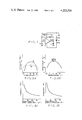
- FIG. 2a is a graph showing a temperature-frequency characteristic of a conventional quartz oscillation circuit
- FIG. 2b shows a temperature-capacitance characteristic of a temperature compensating capacitor of the conventional oscillation circuit
- FIGS. 3a and 3b are graphs showing variation in the oscillation frequency with the capacitance of the input and output capacitors
- FIGS. 4a and 4b show the relationship between the minimum operating voltage and the capacitance of the input capacitor and the consumed current and the capacitance, respectively, when a temperature compensating capacitor is used as the input capacitor;
- FIGS. 5a and 5b show the relationship between the minimum operating voltage and the capacitance of the output capacitor and between the consumed current and the capacitance, respectively, when a temperature compensating capacitor is used as the output capacitor;
- FIGS. 6a and 6b show changes in the minimum operating voltage and consumed current against temperature, respectively
- FIGS. 7a and 7b show the variation in the capacitance of the input capacitor against temperature and the variation in capacitance of the output capacitor against temperature, respectively, the capacitors being used in the oscillation circuit of this invention
- FIGS. 8 and 9 are modified embodiments of a quartz oscillation circuit according to this invention.
- FIG. 10 is a suitable application of this invention in which the quartz oscillation circuit of FIG. 1 is connected to a frequency divider for functioning as a time reference signal generating circuit.
- FIG. 1 a circuitry of a quartz oscillation circuit of this invention, in which a quartz oscillator element 1 is connected between an input terminal IN and an output terminal OUT of an inverter 2 which operates as an amplifier.
- An input capacitor 3 is connected between the input terminal IN and the ground and the output terminal OUT is also connected to the ground through an output capacitor 4.
- Reference numeral 5 depicts a biasing resistor connected in parallel to the quartz oscillator element. Between power supply terminals V DD and V SS is connected an electric battery 6, the terminal V DD being grounded.
- the input and output capacitors have temperature-compensating characteristics.
- the oscillating frequency of the circuit of FIG. 1 would be changed with the ambient temperature along a curve A of the second order as shown in FIG. 2a. Also, changes in oscillation frequency with changes in the input and output capacitors 3 and 4 exhibit negative characteristics as shown in FIGS. 3a and 3b. Thus, a timepiece including such quartz oscillation circuit will go slow at a temperature other than 20° C.
- a temperature-compensating capacitor having a Curie point at about 20° C. and having characteristics of nearly a curve of the second order as shown by a temperature-capacitance characteristics diagram of FIG. 2b, is used as the input or output capacitor, in order to improve the temperature-frequency characteristics as represented by a curve B of FIG. 2a.
- the relation between the capacitance of the output capacitor 4 and the V en is such that the V en decreases with the increase of the capacitance of the capacitor 4, and the relation between the capacitor 4 and the I DD is such that the I DD increases with the capacitance of the capacitor 4 as shown in FIG. 5b. Consequently, when a conventional temperature compensating capacitor having temperature-capacity characteristics shown in FIG. 2b is used as the input capacitor 3 of the quartz oscillation circuit, the V en can be improved at a low-temperature region but causing the I DD to be greatly increased in a high-temperature region. Further, when the temperature compensating capacitor is used as the output capacitor 4, the I DD characteristic can be improved in high-temperature regions, but the V en will be degraded in a low-temperature region, causing the oscillation to be ceased.
- the V en characteristic tends to be degraded in a low-temperature region as represented by a curve A of FIG. 6a, and the I DD tends to be increased in a high-temperature region as represented by a curve A of FIG. 6b. Accordingly, if a conventional temperature-compensating capacitor is employed for the oscillator circuit, the V en characteristic tends to be further degraded in a low-temperature region, and the I DD characteristic tends to be further increased in a high-temperature region.
- the input capacitor 3 has a temperature-compensating capacitor having such temperature-capacitance characteristics as shown in FIG. 7a with a Curie point on the high-temperature side and with a small secondary constant as compared with that of the conventional temperature-compensating capacitors
- the output capacitor 4 has a temperature-compensating capacitor having such temperature-capacitance characteristics as shown in FIG. 7b with a Curie point on the low-temperature side and with a small secondary constant as compared with that of the conventional temperature-compensating capacitors.
- the input capacitor 3 has substantially positive temperature characteristics
- the output capacitor 4 has substantially negative temperature characteristics.
- the capacitance of the capacitor 4 will not be changed in a low-temperature region while the capacitance of the capacitor 3 only is decreased. Therefore, the oscillating frequency in the low-temperature region is compensated by the variation of the capacitance of the capacitor 3.
- the capacitance of the capacitor 3 will not be changed in a high-temperature region, while the capacitance of the capacitor 4 only is decreased. Therefore, the oscillating frequency in the high-temperature region is compensated by the variation of the capacitance of the capacitor 4. As a result, the frequencies are compensated by the means of the capacitors 3 and 4 as represented by the curve B of FIG. 2a.
- the capacitance of the capacitor 4 will not be changed in the low-temperature regions but the capacitance of the capacitor 3 is decreased. Consequently, the V en tends to be decreased with the capacitance of the capacitor 3, accompanying the lowering of temperature as shown in FIG. 4a. As a result, the temperature characteristics of V en are improved as shown by the curve B of FIG. 6a. In the high-temperature regions, on the other hand, the capacitance of the capacitor 3 will not be changed but the capacitance of the capacitor 4 is decreased. Therefore, the I DD tends to be decreased with the decrease in the capacitance of the capacitor 4 as the temperature is raised as shown in FIG. 5b. As a result, the temperature characteristics of I DD are improved as indicated by the curve B of FIG. 6b.
- the quartz oscillation circuit of this invention may include, as shown in FIG. 8, a trimmer capacitor 10 comprising a pair of variable capacitors 10a and 10b which are connected in parallel with the input and output capacitors 3 and 4, respectively, in order to make it possible to adjust the osciallation frequency.
- a trimmer capacitor 10 comprising a pair of variable capacitors 10a and 10b which are connected in parallel with the input and output capacitors 3 and 4, respectively, in order to make it possible to adjust the osciallation frequency.
- both the variable capacitors 10a, 10b can be connected in series with the input and output capacitors.
- variable capacitors 10a, 10b act to balance the temperature-compensating characteristics at the input and output sides of the inverter 2 with narrow variable capacitance ranges.
- the quartz oscillation circuit can be utilized to form a time reference signal generating circuit with a conventional frequency divider circuit connected thereto.
- FIG. 10 a suitable form of time reference signal generating circuit having the quartz oscillation circuit shown in FIG. 1.
- the oscillating signal at the terminal OUT is delivered to a frequency divider circuit 11 to produce a time reference signal ⁇ .
- a variable divider circuit 12 which controls the dividing ratio of the dividing circuit 10 in accordance with the setting of a switch block 13.
- the output signal of the quartz oscillation circuit is supplied to the frequency divider where the frequency of the output signal is divided under control of the circuit 12, thereby to produce the time reference signal ⁇ having an adjusted accuracy. Accordingly, the adjustment of the frequency can be done with no influence to the temperature-compensating characteristics of the quartz oscillation circuit.
- the output frequency of the quartz oscillation circuit is separately compensated in a low-temperature region and in a high-temperature region, and whereby the minimum operating voltage can be lowered in the low-temperature region and, further, the power consumption can be reduced in the high-temperature region. Therefore, even when the circuit is so designed as to consume small power at a normal temperature, there is no probability that the oscillation is stopped. Besides, since the power consumption does not increase in the high-temperature region, the frequency is less varied with the temperature. Thus, according to this invention, it is possible to provide a quartz oscillation circuit which consumes less electric power.
- the fast-slow adjustment can be performed independently of the temperature compensation.
- the fast-slow adjustment is done by adjusting variable capacitors, the mutual influence may be maintained at a low level.
- the quartz oscillation circuit of this invention is applied to an electronic timepiece, the timepiece would be of high precision and enable the life of the battery to be lengthened.
Landscapes
- Physics & Mathematics (AREA)
- General Physics & Mathematics (AREA)
- Oscillators With Electromechanical Resonators (AREA)
- Electric Clocks (AREA)
Abstract
A quartz oscillation circuit used for a time standard of an electronic timepiece, which includes an inverter operating as an amplifier, an input capacitor and an output capacitor, the capacitors having the opposite temperature characteristics to compensate changes in oscillation frequency with the variation of temperature without any increase of the power consumption.
Description
This invention relates to a quartz oscillation circuit for use in electronic timepieces as a source of a time standard.
A quartz oscillation circuit, which has generally been used as a time standard for electronic timepieces, is capable of maintaining an oscillation frequency with a high precision under given conditions but tends to oscillate at varying frequencies depending upon changes in the ambient temperature. In order to improve the temperature characteristics, it is accepted practice to employ elements having specific temperature characteristics, such as capacitors which constitute the oscillation circuit such that the change in frequency of the oscillator caused by the variation in temperature is compensated by the temperature characteristics of the elements. The above temperature-compensation system, however, causes the oscillation circuit to consume increased electric power as well as requires an increased voltage for maintaining the oscillation.
It is an object of this invention to provide a quartz oscillation circuit for electronic timepiece which has an improved oscillation frequency characteristic over a wide temperature range.
Another object of this invention is to provide a quartz oscillation circuit for timepieces with a desirable temperature-power consumption characteristic.
The quartz oscillation circuit according to this invention comprises an inverter and input and output capacitors which have different temperature-capacitance characteristics from each other.
FIG. 1 is a circuit diagram of a quartz oscillation circuit embodying this invention;
FIG. 2a is a graph showing a temperature-frequency characteristic of a conventional quartz oscillation circuit;
FIG. 2b shows a temperature-capacitance characteristic of a temperature compensating capacitor of the conventional oscillation circuit;
FIGS. 3a and 3b are graphs showing variation in the oscillation frequency with the capacitance of the input and output capacitors;
FIGS. 4a and 4b show the relationship between the minimum operating voltage and the capacitance of the input capacitor and the consumed current and the capacitance, respectively, when a temperature compensating capacitor is used as the input capacitor;
FIGS. 5a and 5b show the relationship between the minimum operating voltage and the capacitance of the output capacitor and between the consumed current and the capacitance, respectively, when a temperature compensating capacitor is used as the output capacitor;
FIGS. 6a and 6b show changes in the minimum operating voltage and consumed current against temperature, respectively;
FIGS. 7a and 7b show the variation in the capacitance of the input capacitor against temperature and the variation in capacitance of the output capacitor against temperature, respectively, the capacitors being used in the oscillation circuit of this invention;
FIGS. 8 and 9 are modified embodiments of a quartz oscillation circuit according to this invention; and
FIG. 10 is a suitable application of this invention in which the quartz oscillation circuit of FIG. 1 is connected to a frequency divider for functioning as a time reference signal generating circuit.
In FIG. 1 is shown a circuitry of a quartz oscillation circuit of this invention, in which a quartz oscillator element 1 is connected between an input terminal IN and an output terminal OUT of an inverter 2 which operates as an amplifier. An input capacitor 3 is connected between the input terminal IN and the ground and the output terminal OUT is also connected to the ground through an output capacitor 4. Reference numeral 5 depicts a biasing resistor connected in parallel to the quartz oscillator element. Between power supply terminals VDD and VSS is connected an electric battery 6, the terminal VDD being grounded. In the quartz oscillation circuit of this invention the input and output capacitors have temperature-compensating characteristics.
Assuming that the capacitors 3 and 4 do not have any temperature-compensating characteristics, the oscillating frequency of the circuit of FIG. 1 would be changed with the ambient temperature along a curve A of the second order as shown in FIG. 2a. Also, changes in oscillation frequency with changes in the input and output capacitors 3 and 4 exhibit negative characteristics as shown in FIGS. 3a and 3b. Thus, a timepiece including such quartz oscillation circuit will go slow at a temperature other than 20° C.
Therefore, according to the conventional temperature-compensating system, a temperature-compensating capacitor having a Curie point at about 20° C. and having characteristics of nearly a curve of the second order as shown by a temperature-capacitance characteristics diagram of FIG. 2b, is used as the input or output capacitor, in order to improve the temperature-frequency characteristics as represented by a curve B of FIG. 2a.
With such a quartz oscillation circuit, however, there exists such a relation between the input capacitor 3 and a minimum operation voltage Ven for maintaining the oscillating operation that the minimum operating voltage tends to be increased with the capacitance of the input capacitor 3 as shown by FIG. 4a, and there further exists such a relation between the capacitor 3 and the consumed electric current IDD that the IDD is decreased with the capacitance of the capacitor 3 as shown by FIG. 4b.
Furthermore, as shown in FIG. 5a, the relation between the capacitance of the output capacitor 4 and the Ven is such that the Ven decreases with the increase of the capacitance of the capacitor 4, and the relation between the capacitor 4 and the IDD is such that the IDD increases with the capacitance of the capacitor 4 as shown in FIG. 5b. Consequently, when a conventional temperature compensating capacitor having temperature-capacity characteristics shown in FIG. 2b is used as the input capacitor 3 of the quartz oscillation circuit, the Ven can be improved at a low-temperature region but causing the IDD to be greatly increased in a high-temperature region. Further, when the temperature compensating capacitor is used as the output capacitor 4, the IDD characteristic can be improved in high-temperature regions, but the Ven will be degraded in a low-temperature region, causing the oscillation to be ceased.
In regard to the temperature characteristics of the oscillator circuit, the Ven characteristic tends to be degraded in a low-temperature region as represented by a curve A of FIG. 6a, and the IDD tends to be increased in a high-temperature region as represented by a curve A of FIG. 6b. Accordingly, if a conventional temperature-compensating capacitor is employed for the oscillator circuit, the Ven characteristic tends to be further degraded in a low-temperature region, and the IDD characteristic tends to be further increased in a high-temperature region.
According to the quartz oscillation circuit of this invention, on the other hand, the input capacitor 3 has a temperature-compensating capacitor having such temperature-capacitance characteristics as shown in FIG. 7a with a Curie point on the high-temperature side and with a small secondary constant as compared with that of the conventional temperature-compensating capacitors, and the output capacitor 4 has a temperature-compensating capacitor having such temperature-capacitance characteristics as shown in FIG. 7b with a Curie point on the low-temperature side and with a small secondary constant as compared with that of the conventional temperature-compensating capacitors. Thus, within the temperature range that timepieces are normally utilized, i.e., from -20° C. to 60° C., the input capacitor 3 has substantially positive temperature characteristics, while the output capacitor 4 has substantially negative temperature characteristics.
With the oscillator circuit including the temperature-compensating capacitors 3 and 4, the capacitance of the capacitor 4 will not be changed in a low-temperature region while the capacitance of the capacitor 3 only is decreased. Therefore, the oscillating frequency in the low-temperature region is compensated by the variation of the capacitance of the capacitor 3.
Likewise, the capacitance of the capacitor 3 will not be changed in a high-temperature region, while the capacitance of the capacitor 4 only is decreased. Therefore, the oscillating frequency in the high-temperature region is compensated by the variation of the capacitance of the capacitor 4. As a result, the frequencies are compensated by the means of the capacitors 3 and 4 as represented by the curve B of FIG. 2a.
Furthermore, with the oscillator circuit of this invention, the capacitance of the capacitor 4 will not be changed in the low-temperature regions but the capacitance of the capacitor 3 is decreased. Consequently, the Ven tends to be decreased with the capacitance of the capacitor 3, accompanying the lowering of temperature as shown in FIG. 4a. As a result, the temperature characteristics of Ven are improved as shown by the curve B of FIG. 6a. In the high-temperature regions, on the other hand, the capacitance of the capacitor 3 will not be changed but the capacitance of the capacitor 4 is decreased. Therefore, the IDD tends to be decreased with the decrease in the capacitance of the capacitor 4 as the temperature is raised as shown in FIG. 5b. As a result, the temperature characteristics of IDD are improved as indicated by the curve B of FIG. 6b.
The quartz oscillation circuit of this invention may include, as shown in FIG. 8, a trimmer capacitor 10 comprising a pair of variable capacitors 10a and 10b which are connected in parallel with the input and output capacitors 3 and 4, respectively, in order to make it possible to adjust the osciallation frequency. Alternatively, as shown in FIG. 9, both the variable capacitors 10a, 10b can be connected in series with the input and output capacitors.
In the embodiments shown in FIGS. 8 and 9, the variable capacitors 10a, 10b act to balance the temperature-compensating characteristics at the input and output sides of the inverter 2 with narrow variable capacitance ranges. The quartz oscillation circuit can be utilized to form a time reference signal generating circuit with a conventional frequency divider circuit connected thereto.
In FIG. 10 is shown a suitable form of time reference signal generating circuit having the quartz oscillation circuit shown in FIG. 1. The oscillating signal at the terminal OUT is delivered to a frequency divider circuit 11 to produce a time reference signal φ. To the selected dividing stages of the divider circuit 11 is connected a variable divider circuit 12 which controls the dividing ratio of the dividing circuit 10 in accordance with the setting of a switch block 13.
In the time reference signal generating circuit of FIG. 10, the output signal of the quartz oscillation circuit, of which frequency is substantially irrespective to the changes in the ambient temperature, is supplied to the frequency divider where the frequency of the output signal is divided under control of the circuit 12, thereby to produce the time reference signal φ having an adjusted accuracy. Accordingly, the adjustment of the frequency can be done with no influence to the temperature-compensating characteristics of the quartz oscillation circuit.
According to this invention, as mentioned in the foregoing, the output frequency of the quartz oscillation circuit is separately compensated in a low-temperature region and in a high-temperature region, and whereby the minimum operating voltage can be lowered in the low-temperature region and, further, the power consumption can be reduced in the high-temperature region. Therefore, even when the circuit is so designed as to consume small power at a normal temperature, there is no probability that the oscillation is stopped. Besides, since the power consumption does not increase in the high-temperature region, the frequency is less varied with the temperature. Thus, according to this invention, it is possible to provide a quartz oscillation circuit which consumes less electric power.
Furthermore, when the variable frequency divider circuit is used, the fast-slow adjustment can be performed independently of the temperature compensation. In case that the fast-slow adjustment is done by adjusting variable capacitors, the mutual influence may be maintained at a low level. Thus, when the quartz oscillation circuit of this invention is applied to an electronic timepiece, the timepiece would be of high precision and enable the life of the battery to be lengthened.
Claims (6)
1. A quartz oscillation circuit for electronic timepiece comprising an inverter for operating as an amplifier, an input capacitor connected to the input of the inverter and an output capacitor connected to the output of the inverter, one of the capacitors having substantially positive temperature characteristics and the other capacitor having substantially negative temperature characteristics within a temperature range of from -20° C. to 60° C. that the timepiece is generally used.
2. The quartz oscillation circuit as defined in claim 1 wherein the input capacitor has positive temperature characteristics and wherein the output capacitor has negative temperature characteristics.
3. The quartz oscillation circuit as defined in claim 1 wherein a first variable capacitor is connected in parallel with the input capacitor and a second variable capacitor is connected in parallel with the output capacitor.
4. The quartz oscillation circuit as defined in claim 1 wherein a first variable capacitor is connected in series with the input capacitor and a second variable capacitor is connected in series with the output capacitor.
5. A quartz oscillation circuit for electronic timepiece comprising an inverter having an input terminal and an output terminal, a quartz oscillator element connected between the input and output terminals, a biasing resistor connected in parallel to the quartz oscillator element, a power supply source, a first capacitor connected between the input terminal of the inverter and one of the terminals of the source and a second capacitor connected between the output terminal and one of the terminals of the source, the first and second capacitors have the opposite temperature characteristics to each other within a temperature range of from -20° C. to 60° C. that the timepiece is generally used.
6. An electronic timepiece including
(a) a quartz oscillation circuit comprising an inverter for operating as an amplifier, an input capacitor connected to the input of the inverter and an output capacitor connected to the output of the inverter, one of the capacitors having substantially positive temperature characteristics and the other capacitor having substantially negative temperature characteristics within a temperature range of from -20° C. to 60° C. that the timepiece is generally used, and
(b) a variable divider circuit connected to the output of the quartz oscillation circuit to produce a time unit signal having an adjusted frequency.
Applications Claiming Priority (4)
| Application Number | Priority Date | Filing Date | Title |
|---|---|---|---|
| JP3062078A JPS54123861A (en) | 1978-03-17 | 1978-03-17 | Crystal oscillation circuit for electronic watch |
| JP53-30620 | 1978-03-17 | ||
| JP1656479A JPS55109983A (en) | 1979-02-15 | 1979-02-15 | Electronic timepiece |
| JP54-16564 | 1979-02-15 |
Publications (1)
| Publication Number | Publication Date |
|---|---|
| US4223524A true US4223524A (en) | 1980-09-23 |
Family
ID=26352930
Family Applications (1)
| Application Number | Title | Priority Date | Filing Date |
|---|---|---|---|
| US06/021,114 Expired - Lifetime US4223524A (en) | 1978-03-17 | 1979-03-16 | Quartz oscillation circuit for electronic timepieces |
Country Status (2)
| Country | Link |
|---|---|
| US (1) | US4223524A (en) |
| GB (1) | GB2018539B (en) |
Cited By (13)
| Publication number | Priority date | Publication date | Assignee | Title |
|---|---|---|---|---|
| US4350961A (en) * | 1978-11-10 | 1982-09-21 | Kabushiki Kaisha Daini Seikosha | Electronic timepiece |
| US4560956A (en) * | 1983-09-26 | 1985-12-24 | International Business Machines Corporation | Oscillator with crystal-resistive feedback |
| US4734609A (en) * | 1986-07-25 | 1988-03-29 | Calogic Corporation | Gas density transducer |
| US4825178A (en) * | 1987-08-26 | 1989-04-25 | International Business Machines Corporation | Oscillator with noise rejection and square wave output |
| GB2307120A (en) * | 1995-11-07 | 1997-05-14 | Nec Corp | Quartz oscillator with compensation of frequency variation with temperature using a temperature varying capacitor |
| US5786734A (en) * | 1995-11-13 | 1998-07-28 | Samsung Electronics Co., Ltd. | Temperature compensated ring oscillator on a semiconductor substrate |
| US6163188A (en) * | 1998-07-04 | 2000-12-19 | Faraday Technology Corp. | Input buffer and input-output buffer in full compliance with IDDQ testability |
| US6657506B1 (en) * | 2001-05-23 | 2003-12-02 | Cypress Semiconductor Corp. | Low operating voltage crystal oscillator |
| US8035455B1 (en) | 2005-12-21 | 2011-10-11 | Cypress Semiconductor Corporation | Oscillator amplitude control network |
| US9383333B2 (en) | 2012-05-31 | 2016-07-05 | Ascensia Diabetes Care Holdings Ag | Replaceable multistrip cartridge and biosensor meter |
| US9417229B2 (en) | 2011-12-20 | 2016-08-16 | Ascensia Diabetes Care Holdings Ag | Linear, cartridge-based glucose measurement system |
| US10324081B2 (en) | 2012-05-31 | 2019-06-18 | Ascensia Diabetes Care Holdings Ag | Multistrip cartridge |
| US10533949B2 (en) | 2013-03-12 | 2020-01-14 | Ascensia Diabetes Care Holdings Ag | Test strip meter with a mechanism for pushing the test strip against an optical reader |
Citations (2)
| Publication number | Priority date | Publication date | Assignee | Title |
|---|---|---|---|---|
| GB1135179A (en) * | 1966-09-07 | 1968-12-04 | Centre Electron Horloger | Temperature compensated quartz controlled oscillating circuit |
| US3676801A (en) * | 1970-10-28 | 1972-07-11 | Motorola Inc | Stabilized complementary micro-power square wave oscillator |
-
1979
- 1979-03-16 GB GB7909413A patent/GB2018539B/en not_active Expired
- 1979-03-16 US US06/021,114 patent/US4223524A/en not_active Expired - Lifetime
Patent Citations (2)
| Publication number | Priority date | Publication date | Assignee | Title |
|---|---|---|---|---|
| GB1135179A (en) * | 1966-09-07 | 1968-12-04 | Centre Electron Horloger | Temperature compensated quartz controlled oscillating circuit |
| US3676801A (en) * | 1970-10-28 | 1972-07-11 | Motorola Inc | Stabilized complementary micro-power square wave oscillator |
Cited By (19)
| Publication number | Priority date | Publication date | Assignee | Title |
|---|---|---|---|---|
| US4350961A (en) * | 1978-11-10 | 1982-09-21 | Kabushiki Kaisha Daini Seikosha | Electronic timepiece |
| US4560956A (en) * | 1983-09-26 | 1985-12-24 | International Business Machines Corporation | Oscillator with crystal-resistive feedback |
| US4734609A (en) * | 1986-07-25 | 1988-03-29 | Calogic Corporation | Gas density transducer |
| US4825178A (en) * | 1987-08-26 | 1989-04-25 | International Business Machines Corporation | Oscillator with noise rejection and square wave output |
| GB2307120A (en) * | 1995-11-07 | 1997-05-14 | Nec Corp | Quartz oscillator with compensation of frequency variation with temperature using a temperature varying capacitor |
| GB2307120B (en) * | 1995-11-07 | 1999-02-10 | Nec Corp | Quartz oscillator |
| US5952894A (en) * | 1995-11-07 | 1999-09-14 | Nec Corporation | Resonant circuit having a reactance for temperature compensation |
| US5786734A (en) * | 1995-11-13 | 1998-07-28 | Samsung Electronics Co., Ltd. | Temperature compensated ring oscillator on a semiconductor substrate |
| US6163188A (en) * | 1998-07-04 | 2000-12-19 | Faraday Technology Corp. | Input buffer and input-output buffer in full compliance with IDDQ testability |
| US6657506B1 (en) * | 2001-05-23 | 2003-12-02 | Cypress Semiconductor Corp. | Low operating voltage crystal oscillator |
| US8035455B1 (en) | 2005-12-21 | 2011-10-11 | Cypress Semiconductor Corporation | Oscillator amplitude control network |
| US9417229B2 (en) | 2011-12-20 | 2016-08-16 | Ascensia Diabetes Care Holdings Ag | Linear, cartridge-based glucose measurement system |
| US11226327B2 (en) | 2011-12-20 | 2022-01-18 | Ascensia Diabetes Care Holdings Ag | Linear, cartridge-based glucose measurement system |
| US9383333B2 (en) | 2012-05-31 | 2016-07-05 | Ascensia Diabetes Care Holdings Ag | Replaceable multistrip cartridge and biosensor meter |
| US10073051B2 (en) | 2012-05-31 | 2018-09-11 | Ascensia Diabetes Care Holdings Ag | Replaceable multistrip cartridge and biosensor meter |
| US10324081B2 (en) | 2012-05-31 | 2019-06-18 | Ascensia Diabetes Care Holdings Ag | Multistrip cartridge |
| US10656112B2 (en) | 2012-05-31 | 2020-05-19 | Ascensia Diabetes Care Holdings Ag | Replaceable multistrip cartridge and biosenser meter |
| US10753923B2 (en) | 2012-05-31 | 2020-08-25 | Ascensia Diabetes Care Holdings Ag | Multistrip cartridge |
| US10533949B2 (en) | 2013-03-12 | 2020-01-14 | Ascensia Diabetes Care Holdings Ag | Test strip meter with a mechanism for pushing the test strip against an optical reader |
Also Published As
| Publication number | Publication date |
|---|---|
| GB2018539A (en) | 1979-10-17 |
| GB2018539B (en) | 1982-06-03 |
Similar Documents
| Publication | Publication Date | Title |
|---|---|---|
| RU2216098C2 (en) | Quartz-crystal controlled oscillator and method for generating oscillator output signal | |
| US4223524A (en) | Quartz oscillation circuit for electronic timepieces | |
| US5473289A (en) | Temperature compensated crystal oscillator | |
| US5481229A (en) | Low power temperature compensated crystal oscillator | |
| GB2097969A (en) | Electronic timepiece | |
| KR960016733B1 (en) | Oscillation circuit | |
| US4020426A (en) | Temperature compensation circuit for crystal oscillator | |
| US6734747B1 (en) | Piezoelectric oscillator | |
| US3959744A (en) | CMOS oscillator having bias circuit outside oscillator feedback loop | |
| US3641461A (en) | Temperature compensated crystal oscillator | |
| JPH01108801A (en) | Temperature compensation type pizo- electric oscillator | |
| GB2084421A (en) | Oscillator Circuit With Low Current Consumption | |
| US5101178A (en) | Crystal oscillator having frequency adjustment responsive to power supply voltage | |
| JPH0469450B2 (en) | ||
| KR20010067389A (en) | Low frequency quartz oscillator device with improved thermal characteristics | |
| US7005934B2 (en) | Crystal oscillator with temperature compensated through a vibrator current control circuit | |
| US5770980A (en) | Fast starting oscillator | |
| US4821001A (en) | Circuit oscillator | |
| US4104599A (en) | Crystal oscillating circuit | |
| US4142161A (en) | Crystal oscillator | |
| JP2002135051A (en) | Piezoelectric oscillator | |
| US3483485A (en) | Temperature-stabilised crystal-controlled oscillator | |
| JPS6115607B2 (en) | ||
| SU907764A1 (en) | Temperature compensated crystal generator | |
| JP2545568B2 (en) | Piezoelectric oscillator |