US4117048A - Apparatus for introducing gas into a liquid - Google Patents
Apparatus for introducing gas into a liquid Download PDFInfo
- Publication number
- US4117048A US4117048A US05/702,052 US70205276A US4117048A US 4117048 A US4117048 A US 4117048A US 70205276 A US70205276 A US 70205276A US 4117048 A US4117048 A US 4117048A
- Authority
- US
- United States
- Prior art keywords
- liquid
- ribs
- gas
- passages
- rotor
- Prior art date
- Legal status (The legal status is an assumption and is not a legal conclusion. Google has not performed a legal analysis and makes no representation as to the accuracy of the status listed.)
- Expired - Lifetime
Links
- 239000007788 liquid Substances 0.000 title claims abstract description 62
- 239000010865 sewage Substances 0.000 claims abstract description 6
- 238000005273 aeration Methods 0.000 claims description 4
- 238000011144 upstream manufacturing Methods 0.000 claims description 4
- 230000001939 inductive effect Effects 0.000 claims 1
- 239000007789 gas Substances 0.000 abstract description 43
- QVGXLLKOCUKJST-UHFFFAOYSA-N atomic oxygen Chemical compound [O] QVGXLLKOCUKJST-UHFFFAOYSA-N 0.000 abstract description 12
- 229910052760 oxygen Inorganic materials 0.000 abstract description 12
- 239000001301 oxygen Substances 0.000 abstract description 12
- 239000002351 wastewater Substances 0.000 abstract description 9
- XLYOFNOQVPJJNP-UHFFFAOYSA-N water Substances O XLYOFNOQVPJJNP-UHFFFAOYSA-N 0.000 description 5
- 230000000694 effects Effects 0.000 description 4
- 239000007791 liquid phase Substances 0.000 description 3
- 239000002245 particle Substances 0.000 description 3
- QGZKDVFQNNGYKY-UHFFFAOYSA-N Ammonia Chemical compound N QGZKDVFQNNGYKY-UHFFFAOYSA-N 0.000 description 2
- CURLTUGMZLYLDI-UHFFFAOYSA-N Carbon dioxide Chemical compound O=C=O CURLTUGMZLYLDI-UHFFFAOYSA-N 0.000 description 2
- 239000000919 ceramic Substances 0.000 description 2
- 239000000356 contaminant Substances 0.000 description 2
- 238000007599 discharging Methods 0.000 description 2
- 238000006073 displacement reaction Methods 0.000 description 2
- 239000002184 metal Substances 0.000 description 2
- 229910052751 metal Inorganic materials 0.000 description 2
- 238000000746 purification Methods 0.000 description 2
- 239000007787 solid Substances 0.000 description 2
- 239000004575 stone Substances 0.000 description 2
- 229920003002 synthetic resin Polymers 0.000 description 2
- 239000000057 synthetic resin Substances 0.000 description 2
- 230000001133 acceleration Effects 0.000 description 1
- 229910021529 ammonia Inorganic materials 0.000 description 1
- 230000000903 blocking effect Effects 0.000 description 1
- 229910002092 carbon dioxide Inorganic materials 0.000 description 1
- 239000001569 carbon dioxide Substances 0.000 description 1
- 238000005352 clarification Methods 0.000 description 1
- 238000000354 decomposition reaction Methods 0.000 description 1
- 238000009792 diffusion process Methods 0.000 description 1
- 238000004090 dissolution Methods 0.000 description 1
- 239000003651 drinking water Substances 0.000 description 1
- 235000020188 drinking water Nutrition 0.000 description 1
- 238000005265 energy consumption Methods 0.000 description 1
- 238000005188 flotation Methods 0.000 description 1
- 238000002347 injection Methods 0.000 description 1
- 239000007924 injection Substances 0.000 description 1
- 239000000463 material Substances 0.000 description 1
- 150000002739 metals Chemical class 0.000 description 1
- 238000000034 method Methods 0.000 description 1
- 239000008239 natural water Substances 0.000 description 1
- 230000001473 noxious effect Effects 0.000 description 1
- 230000010355 oscillation Effects 0.000 description 1
- 239000012071 phase Substances 0.000 description 1
- 238000005086 pumping Methods 0.000 description 1
- 238000000926 separation method Methods 0.000 description 1
- 238000010008 shearing Methods 0.000 description 1
- 239000010802 sludge Substances 0.000 description 1
- 238000005507 spraying Methods 0.000 description 1
- 231100000331 toxic Toxicity 0.000 description 1
- 230000002588 toxic effect Effects 0.000 description 1
- 238000004065 wastewater treatment Methods 0.000 description 1
Images


Classifications
-
- C—CHEMISTRY; METALLURGY
- C02—TREATMENT OF WATER, WASTE WATER, SEWAGE, OR SLUDGE
- C02F—TREATMENT OF WATER, WASTE WATER, SEWAGE, OR SLUDGE
- C02F3/00—Biological treatment of water, waste water, or sewage
- C02F3/02—Aerobic processes
- C02F3/12—Activated sludge processes
- C02F3/1278—Provisions for mixing or aeration of the mixed liquor
- C02F3/1294—"Venturi" aeration means
-
- B—PERFORMING OPERATIONS; TRANSPORTING
- B01—PHYSICAL OR CHEMICAL PROCESSES OR APPARATUS IN GENERAL
- B01F—MIXING, e.g. DISSOLVING, EMULSIFYING OR DISPERSING
- B01F23/00—Mixing according to the phases to be mixed, e.g. dispersing or emulsifying
- B01F23/20—Mixing gases with liquids
- B01F23/23—Mixing gases with liquids by introducing gases into liquid media, e.g. for producing aerated liquids
- B01F23/231—Mixing gases with liquids by introducing gases into liquid media, e.g. for producing aerated liquids by bubbling
- B01F23/23105—Arrangement or manipulation of the gas bubbling devices
- B01F23/2312—Diffusers
- B01F23/23123—Diffusers consisting of rigid porous or perforated material
-
- B—PERFORMING OPERATIONS; TRANSPORTING
- B01—PHYSICAL OR CHEMICAL PROCESSES OR APPARATUS IN GENERAL
- B01F—MIXING, e.g. DISSOLVING, EMULSIFYING OR DISPERSING
- B01F23/00—Mixing according to the phases to be mixed, e.g. dispersing or emulsifying
- B01F23/20—Mixing gases with liquids
- B01F23/23—Mixing gases with liquids by introducing gases into liquid media, e.g. for producing aerated liquids
- B01F23/233—Mixing gases with liquids by introducing gases into liquid media, e.g. for producing aerated liquids using driven stirrers with completely immersed stirring elements
- B01F23/2331—Mixing gases with liquids by introducing gases into liquid media, e.g. for producing aerated liquids using driven stirrers with completely immersed stirring elements characterised by the introduction of the gas along the axis of the stirrer or along the stirrer elements
- B01F23/23313—Mixing gases with liquids by introducing gases into liquid media, e.g. for producing aerated liquids using driven stirrers with completely immersed stirring elements characterised by the introduction of the gas along the axis of the stirrer or along the stirrer elements through a separate conduit substantially parallel with the stirrer axis
-
- B—PERFORMING OPERATIONS; TRANSPORTING
- B01—PHYSICAL OR CHEMICAL PROCESSES OR APPARATUS IN GENERAL
- B01F—MIXING, e.g. DISSOLVING, EMULSIFYING OR DISPERSING
- B01F23/00—Mixing according to the phases to be mixed, e.g. dispersing or emulsifying
- B01F23/20—Mixing gases with liquids
- B01F23/23—Mixing gases with liquids by introducing gases into liquid media, e.g. for producing aerated liquids
- B01F23/233—Mixing gases with liquids by introducing gases into liquid media, e.g. for producing aerated liquids using driven stirrers with completely immersed stirring elements
- B01F23/2331—Mixing gases with liquids by introducing gases into liquid media, e.g. for producing aerated liquids using driven stirrers with completely immersed stirring elements characterised by the introduction of the gas along the axis of the stirrer or along the stirrer elements
- B01F23/23314—Mixing gases with liquids by introducing gases into liquid media, e.g. for producing aerated liquids using driven stirrers with completely immersed stirring elements characterised by the introduction of the gas along the axis of the stirrer or along the stirrer elements through a hollow stirrer element
-
- B—PERFORMING OPERATIONS; TRANSPORTING
- B01—PHYSICAL OR CHEMICAL PROCESSES OR APPARATUS IN GENERAL
- B01F—MIXING, e.g. DISSOLVING, EMULSIFYING OR DISPERSING
- B01F23/00—Mixing according to the phases to be mixed, e.g. dispersing or emulsifying
- B01F23/20—Mixing gases with liquids
- B01F23/23—Mixing gases with liquids by introducing gases into liquid media, e.g. for producing aerated liquids
- B01F23/233—Mixing gases with liquids by introducing gases into liquid media, e.g. for producing aerated liquids using driven stirrers with completely immersed stirring elements
- B01F23/2332—Mixing gases with liquids by introducing gases into liquid media, e.g. for producing aerated liquids using driven stirrers with completely immersed stirring elements the stirrer rotating about a horizontal axis; Stirrers therefor
-
- B—PERFORMING OPERATIONS; TRANSPORTING
- B01—PHYSICAL OR CHEMICAL PROCESSES OR APPARATUS IN GENERAL
- B01F—MIXING, e.g. DISSOLVING, EMULSIFYING OR DISPERSING
- B01F23/00—Mixing according to the phases to be mixed, e.g. dispersing or emulsifying
- B01F23/20—Mixing gases with liquids
- B01F23/23—Mixing gases with liquids by introducing gases into liquid media, e.g. for producing aerated liquids
- B01F23/233—Mixing gases with liquids by introducing gases into liquid media, e.g. for producing aerated liquids using driven stirrers with completely immersed stirring elements
- B01F23/2334—Mixing gases with liquids by introducing gases into liquid media, e.g. for producing aerated liquids using driven stirrers with completely immersed stirring elements provided with stationary guiding means surrounding at least partially the stirrer
- B01F23/23341—Mixing gases with liquids by introducing gases into liquid media, e.g. for producing aerated liquids using driven stirrers with completely immersed stirring elements provided with stationary guiding means surrounding at least partially the stirrer with tubes surrounding the stirrer
-
- B—PERFORMING OPERATIONS; TRANSPORTING
- B01—PHYSICAL OR CHEMICAL PROCESSES OR APPARATUS IN GENERAL
- B01F—MIXING, e.g. DISSOLVING, EMULSIFYING OR DISPERSING
- B01F23/00—Mixing according to the phases to be mixed, e.g. dispersing or emulsifying
- B01F23/20—Mixing gases with liquids
- B01F23/23—Mixing gases with liquids by introducing gases into liquid media, e.g. for producing aerated liquids
- B01F23/233—Mixing gases with liquids by introducing gases into liquid media, e.g. for producing aerated liquids using driven stirrers with completely immersed stirring elements
- B01F23/2336—Mixing gases with liquids by introducing gases into liquid media, e.g. for producing aerated liquids using driven stirrers with completely immersed stirring elements characterised by the location of the place of introduction of the gas relative to the stirrer
- B01F23/23364—Mixing gases with liquids by introducing gases into liquid media, e.g. for producing aerated liquids using driven stirrers with completely immersed stirring elements characterised by the location of the place of introduction of the gas relative to the stirrer the gas being introduced between the stirrer elements
-
- B—PERFORMING OPERATIONS; TRANSPORTING
- B01—PHYSICAL OR CHEMICAL PROCESSES OR APPARATUS IN GENERAL
- B01F—MIXING, e.g. DISSOLVING, EMULSIFYING OR DISPERSING
- B01F25/00—Flow mixers; Mixers for falling materials, e.g. solid particles
- B01F25/30—Injector mixers
- B01F25/31—Injector mixers in conduits or tubes through which the main component flows
- B01F25/312—Injector mixers in conduits or tubes through which the main component flows with Venturi elements; Details thereof
-
- C—CHEMISTRY; METALLURGY
- C02—TREATMENT OF WATER, WASTE WATER, SEWAGE, OR SLUDGE
- C02F—TREATMENT OF WATER, WASTE WATER, SEWAGE, OR SLUDGE
- C02F3/00—Biological treatment of water, waste water, or sewage
- C02F3/02—Aerobic processes
- C02F3/12—Activated sludge processes
- C02F3/14—Activated sludge processes using surface aeration
- C02F3/18—Activated sludge processes using surface aeration the aerator having a horizontal axis
-
- C—CHEMISTRY; METALLURGY
- C02—TREATMENT OF WATER, WASTE WATER, SEWAGE, OR SLUDGE
- C02F—TREATMENT OF WATER, WASTE WATER, SEWAGE, OR SLUDGE
- C02F3/00—Biological treatment of water, waste water, or sewage
- C02F3/02—Aerobic processes
- C02F3/12—Activated sludge processes
- C02F3/20—Activated sludge processes using diffusers
- C02F3/205—Moving, e.g. rotary, diffusers; Stationary diffusers with moving, e.g. rotary, distributors
- C02F3/207—Moving, e.g. rotary, diffusers; Stationary diffusers with moving, e.g. rotary, distributors with axial thrust propellers
-
- B—PERFORMING OPERATIONS; TRANSPORTING
- B01—PHYSICAL OR CHEMICAL PROCESSES OR APPARATUS IN GENERAL
- B01F—MIXING, e.g. DISSOLVING, EMULSIFYING OR DISPERSING
- B01F23/00—Mixing according to the phases to be mixed, e.g. dispersing or emulsifying
- B01F23/20—Mixing gases with liquids
- B01F23/23—Mixing gases with liquids by introducing gases into liquid media, e.g. for producing aerated liquids
- B01F23/233—Mixing gases with liquids by introducing gases into liquid media, e.g. for producing aerated liquids using driven stirrers with completely immersed stirring elements
- B01F23/2331—Mixing gases with liquids by introducing gases into liquid media, e.g. for producing aerated liquids using driven stirrers with completely immersed stirring elements characterised by the introduction of the gas along the axis of the stirrer or along the stirrer elements
- B01F23/23311—Mixing gases with liquids by introducing gases into liquid media, e.g. for producing aerated liquids using driven stirrers with completely immersed stirring elements characterised by the introduction of the gas along the axis of the stirrer or along the stirrer elements through a hollow stirrer axis
-
- B—PERFORMING OPERATIONS; TRANSPORTING
- B01—PHYSICAL OR CHEMICAL PROCESSES OR APPARATUS IN GENERAL
- B01F—MIXING, e.g. DISSOLVING, EMULSIFYING OR DISPERSING
- B01F23/00—Mixing according to the phases to be mixed, e.g. dispersing or emulsifying
- B01F23/20—Mixing gases with liquids
- B01F23/23—Mixing gases with liquids by introducing gases into liquid media, e.g. for producing aerated liquids
- B01F23/233—Mixing gases with liquids by introducing gases into liquid media, e.g. for producing aerated liquids using driven stirrers with completely immersed stirring elements
- B01F23/2335—Mixing gases with liquids by introducing gases into liquid media, e.g. for producing aerated liquids using driven stirrers with completely immersed stirring elements characterised by the direction of introduction of the gas relative to the stirrer
- B01F23/23351—Mixing gases with liquids by introducing gases into liquid media, e.g. for producing aerated liquids using driven stirrers with completely immersed stirring elements characterised by the direction of introduction of the gas relative to the stirrer the gas moving along the axis of rotation
-
- B—PERFORMING OPERATIONS; TRANSPORTING
- B01—PHYSICAL OR CHEMICAL PROCESSES OR APPARATUS IN GENERAL
- B01F—MIXING, e.g. DISSOLVING, EMULSIFYING OR DISPERSING
- B01F23/00—Mixing according to the phases to be mixed, e.g. dispersing or emulsifying
- B01F23/20—Mixing gases with liquids
- B01F23/23—Mixing gases with liquids by introducing gases into liquid media, e.g. for producing aerated liquids
- B01F23/233—Mixing gases with liquids by introducing gases into liquid media, e.g. for producing aerated liquids using driven stirrers with completely immersed stirring elements
- B01F23/2335—Mixing gases with liquids by introducing gases into liquid media, e.g. for producing aerated liquids using driven stirrers with completely immersed stirring elements characterised by the direction of introduction of the gas relative to the stirrer
- B01F23/23352—Mixing gases with liquids by introducing gases into liquid media, e.g. for producing aerated liquids using driven stirrers with completely immersed stirring elements characterised by the direction of introduction of the gas relative to the stirrer the gas moving perpendicular to the axis of rotation
-
- B—PERFORMING OPERATIONS; TRANSPORTING
- B01—PHYSICAL OR CHEMICAL PROCESSES OR APPARATUS IN GENERAL
- B01F—MIXING, e.g. DISSOLVING, EMULSIFYING OR DISPERSING
- B01F23/00—Mixing according to the phases to be mixed, e.g. dispersing or emulsifying
- B01F23/20—Mixing gases with liquids
- B01F23/23—Mixing gases with liquids by introducing gases into liquid media, e.g. for producing aerated liquids
- B01F23/237—Mixing gases with liquids by introducing gases into liquid media, e.g. for producing aerated liquids characterised by the physical or chemical properties of gases or vapours introduced in the liquid media
- B01F23/2376—Mixing gases with liquids by introducing gases into liquid media, e.g. for producing aerated liquids characterised by the physical or chemical properties of gases or vapours introduced in the liquid media characterised by the gas being introduced
- B01F23/23761—Aerating, i.e. introducing oxygen containing gas in liquids
- B01F23/237612—Oxygen
-
- B—PERFORMING OPERATIONS; TRANSPORTING
- B01—PHYSICAL OR CHEMICAL PROCESSES OR APPARATUS IN GENERAL
- B01F—MIXING, e.g. DISSOLVING, EMULSIFYING OR DISPERSING
- B01F27/00—Mixers with rotary stirring devices in fixed receptacles; Kneaders
- B01F27/05—Stirrers
- B01F27/11—Stirrers characterised by the configuration of the stirrers
- B01F27/113—Propeller-shaped stirrers for producing an axial flow, e.g. shaped like a ship or aircraft propeller
- B01F27/1131—Propeller-shaped stirrers for producing an axial flow, e.g. shaped like a ship or aircraft propeller with holes in the propeller blade surface
-
- B—PERFORMING OPERATIONS; TRANSPORTING
- B01—PHYSICAL OR CHEMICAL PROCESSES OR APPARATUS IN GENERAL
- B01F—MIXING, e.g. DISSOLVING, EMULSIFYING OR DISPERSING
- B01F27/00—Mixers with rotary stirring devices in fixed receptacles; Kneaders
- B01F27/05—Stirrers
- B01F27/11—Stirrers characterised by the configuration of the stirrers
- B01F27/115—Stirrers characterised by the configuration of the stirrers comprising discs or disc-like elements essentially perpendicular to the stirrer shaft axis
- B01F27/1155—Stirrers characterised by the configuration of the stirrers comprising discs or disc-like elements essentially perpendicular to the stirrer shaft axis with interconnected discs, forming open frameworks or cages
-
- B—PERFORMING OPERATIONS; TRANSPORTING
- B01—PHYSICAL OR CHEMICAL PROCESSES OR APPARATUS IN GENERAL
- B01F—MIXING, e.g. DISSOLVING, EMULSIFYING OR DISPERSING
- B01F27/00—Mixers with rotary stirring devices in fixed receptacles; Kneaders
- B01F27/60—Mixers with rotary stirring devices in fixed receptacles; Kneaders with stirrers rotating about a horizontal or inclined axis
-
- B—PERFORMING OPERATIONS; TRANSPORTING
- B01—PHYSICAL OR CHEMICAL PROCESSES OR APPARATUS IN GENERAL
- B01F—MIXING, e.g. DISSOLVING, EMULSIFYING OR DISPERSING
- B01F27/00—Mixers with rotary stirring devices in fixed receptacles; Kneaders
- B01F27/80—Mixers with rotary stirring devices in fixed receptacles; Kneaders with stirrers rotating about a substantially vertical axis
-
- Y—GENERAL TAGGING OF NEW TECHNOLOGICAL DEVELOPMENTS; GENERAL TAGGING OF CROSS-SECTIONAL TECHNOLOGIES SPANNING OVER SEVERAL SECTIONS OF THE IPC; TECHNICAL SUBJECTS COVERED BY FORMER USPC CROSS-REFERENCE ART COLLECTIONS [XRACs] AND DIGESTS
- Y02—TECHNOLOGIES OR APPLICATIONS FOR MITIGATION OR ADAPTATION AGAINST CLIMATE CHANGE
- Y02W—CLIMATE CHANGE MITIGATION TECHNOLOGIES RELATED TO WASTEWATER TREATMENT OR WASTE MANAGEMENT
- Y02W10/00—Technologies for wastewater treatment
- Y02W10/10—Biological treatment of water, waste water, or sewage
Definitions
- the present invention relates to an apparatus or device for introducing a gas into a liquid and, more particularly, to an apparatus for treating a liquid with the gas, e.g. to dissolve the gas or a component thereof into the liquid.
- Apparatus for treating a liquid with the gas can have many utilities and of particularly great interest at the present time are systems for dissolving oxygen in liquids such as waste water as part of a purification thereof.
- Waste-water purification systems may involve the aerobic decomposition of organic components of waste water, e.g. in an activated sludge tank, with the result that a purified decantate can be removed free from toxic or noxious components.
- a purified decantate can be removed free from toxic or noxious components.
- other gases such as carbon dioxide, into water for various purposes, to dissolve ammonia in water and, in general, treat a liquid phase with gas phase.
- Another object of the invention is to provide a system for the purposes described which is less prone to blocking or obstruction than the earlier systems, is particularly suited for the treatment of waste water, and which is free from other disadvantages characterizing gas-dispersing systems in finely divided form in a liquid phase.
- venturi nozzle is here used to define a passage which is initially (in the direction of flow of the liquid) converges relatively sharply to a minimum spacing and thereafter widens more slowly.
- gas-discharging means is disposed immediately upstream of this last divergence.
- a gap between the ribs shaped as a venturi nozzle in the manner described, with the gas-discharging means disposed ahead of the divergence, permits the liquid to suck the gas from the gas outlet passages and shear the gas at high velocity in the constriction from the gas flow in the form of especially fine bubbles.
- the gas is sucked by the liquid from the passages by the venturi effect.
- the gas discharge means can be a perforated plate or a porous body, e.g. an aeration stone made of any convenient material, e.g. sintered particles of metal, ceramic or synthetic resin, which is perferably disposed on an upper or lower surface of the rib.
- the ribs can be oriented horizontally.
- the ribs are connected with a source of gas, e.g. oxygen or atmospheric air whose oxygen is to be dissolved in waste water by pipes feeding the group of ribs, the ribs being hollow to distribute the gas to the several gas-permeable members forming the discharge means.
- a source of gas e.g. oxygen or atmospheric air whose oxygen is to be dissolved in waste water
- the ribs being hollow to distribute the gas to the several gas-permeable members forming the discharge means.
- the ribs can communicate with a common chamber supply with the gas or may be provided with a manifold which feeds the gas to them.
- the bubbles sheared by the high-velocity liquid in the narrowest part of each constriction are entrained by the liquid flowing between the ribs and are thereafter dispersed in the remaining body of liquid. Because of the relatively low volume of each bubble, the bubbles rapidly dissolve.
- the divergence at the end of the flow passage between each pair of ribs acts as a diffuser in which velocity is transformed again into pressure after pressure has been transformed into an increased velocity in the narrowest part of the constriction thereby minimizing the total energy consumption of the device.
- the displacement of the liquid can be effected by a submerged pump adapted to drive the liquid through the gaps between the ribs of the gas distributor.
- a submerged pump adapted to drive the liquid through the gaps between the ribs of the gas distributor.
- the gas distributor in the form of a grid of such ribs of the outlet of a nozzle or duct traversed by the liquid and having the submerged pump at the intake end.
- nozzles can be provided to inject the carrier liquid into the gap between the ribs so that the displacement of the larger body of liquid is effected in accordance with ejector principles.
- the ribs are formed as annular or ring-shaped members, e.g. as horizontal annular hollow discs at the end of a vertical pipe and are spaced along the axis thereof to provide radial venturi gaps.
- the entire assembly can be received in a sewage clarification tank and a pump can be provided to circulate water axially downwardly through the duct and radially outwardly through the annular ribs.
- the water circulation device can be used to circulate the contents of the tank as well as aerate the latter.
- the pump motor can be disposed above the liquid level, the shaft of the pump extending vertically into the assembly as described.
- a pump rotor or impeller can be formed from a plurality of radial pump wheels which can alternate with annular ribs of the type described and furthermore the annular ribs and the radial pump wheels can be rotatable counter to one another, i.e. in opposite senses.
- Such an arrangement not only permits a more effective circulation of liquid downwardly and outwardly through the unit within the clarifier vessel but also increases the relative velocity between the liquid and the ribs, thereby increasing the shearing effect and reducing the diameter of the gas bubbles which are formed.
- One or more ribs in any of the embodiments described can be provided with one or more vibrators to increase the relative velocity of the liquid and the ribs. The brief accelerations imparted by the vibrator to the ribs has been found to produce especially small bubbles and permits the flow velocity of the liquid to be reduced without detrimentally affecting the overall efficiency of the device.
- ribs are provided as multiblade propellers cooperating with fixed ribs.
- the ribs can also be the liquid displacing vanes of a radial pump.
- the invention is not only applicable to dissolution of gases in liquids but may be used in addition for the separation of liquids and solid particles by flotation, i.e. systems in which gas bubbles are generated to adhere to solid particles.
- FIG. 1 is a vertical section through a plurality of horizontally disposed ribs, drawn to an enlarged scale and illustrating diagrammatically the principles of the present invention
- FIG. 2 is an axial cross section through an apparatus according to the present invention, also diagrammatically represented;
- FIG. 3 is a vertical axial cross-sectional view through a gas-dispersing device for a waste water treatment plant
- FIG. 4 is a section similar to FIG. 3 through another device for this purpose, also according to the invention.
- FIG. 5 is a view similar to FIG. 3 but illustrating another embodiment of the invention.
- FIG. 6 is a section taken along the line VI--VI of FIG. 5;
- FIG. 7 is a vertical section through another embodiment.
- FIG. 1 shows three ribs in schematic cross section forming a grid of a gas-dispersing device, e.g. of the type shown in FIG. 2.
- the ribs 1, 2 and 3 are of aerodynamic profile and thus each has a streamlined or rounded upstream end as represented at 1a, 2a, 3a against which the oncoming stream of liquid represented by the arrow L impinges.
- the upper and lower surface 1b and 1c, 2b and 2c, 3b and 3c define a pair of flow passages represented generally at 1d and 2d respectively.
- Each of these passages initially converges in a zone a, remains constant over a zone b and diverges over a zone c, the divergence of zone c being less rigid than the convergence in the zone a.
- the zone b represents the maximum constriction of the flow passages 1d and 2d.
- the flow passages 1d and 2d thus constitute venturi nozzles which tend to draw gas into the liquid from the passages in a block 4 disposed along the upper and lower surfaces of each rib substantially over a major portion of the width of the zone b.
- the blocks 4 are composed of sintered metals, ceramic or synthetic resin and are permeable to gas so as to effectively have a multiplicity of capillary passages from which the gas can be sucked by the venturi effect. Because of the constricting nature of the venturi nozzle, the liquid has a maximum flow velocity in the zone b.
- each rib 1, 2, 3 is provided with seats 1e, 2e and 4e in which the gas permeable member 4 is received.
- the gas As the gas is torn from the passages of its permeable block 4, it is entrained with a liquid phase and dispersed into surrounding liquid at the downstream side d of the device. Gas is supplied to the ribs via a line represented diagrammatically at 5. It will be apparent that the ribs extend horizontally so that the venturi nozzles are generally flat and horizontal and are not readily obstructed by contaminants contained in the waste water or sewage.
- FIG. 2 illustrates a gas-dispersal device particularly adapted to enriching waste water or sewage with oxygen or for treating natural water, e.g. drinking water with oxygen by aeration.
- a submersible pump 8 is mounted coaxially via strut 7d in the intake 7a which is provided with a large-mesh grid 10 of a basket shape to prevent entry of objects which may interfere with the pumping operation.
- the pump 8 has a propeller-type 8a which drives the liquid in the direction of arrow 8b.
- the duct 7 Downstream of the pump 8, 8a but upstream of the grid 6a, the duct 7 is provided with guide plates 9 to reduce turbulence and maintain approximately laminar flow of the liquid through the grid 6a.
- the latter is mounted by a vertical rib 6b upon the duct 7 and can be supplied with oxygen via the line 5 previously described.
- the vertical rib 6b can be mounted elastically at 6c and 6d upon the wall of the duct 7 and can be connected to a vibrator 6e to produce oscillations of the ribs transverse to the direction of liquid flow as represented by the arrow e.
- the ribs 6 disperse the gas into the liquid as the latter flows in the direction of arrow 8b through the device in the manner described in FIG. 1.
- FIG. 2 can be carried on a support, represented diagrammatically at 7e enabling it to be rotated about a vertical axis or entrained in a circular path about a vertical axis in the clarifier tank in which it is disposed for aerating the sewage.
- FIG. 3 shows, in diagrammatic cross section another embodiment of the invention in which a vertically extending duct 11 is submerged in a clarifier tank and is provided with a plurality of vertically spaced horizontal annular ribs 12 as described for the ribs 1 through 3 previously.
- the ribs 12 are supported on vertical struts 12a suspended from an outwardly extending flange 11a of the duct 11.
- the ribs are formed with the gas-permeable bodies 4 mentioned previously and define radially extending venturi gaps in the manner also described above.
- a motor 16 has a shaft 15 carrying a rotor 15a which is formed with a plurality of angularly spaced struts 15b attaching a downwardly converging shell 15c to this shaft 15. On this shell 15c there are a multiplicity of vertical vanes 13 which form a radial pump forcing the liquid outwardly between the ribs 12. The liquid is drawn downwardly over the top of the duct 11 as shown by the arrows in FIG. 3. This arrangement operates in the manner described with respect to FIG. 2 except that the flow of liquid is radial with respect to the pump rather than axial.
- FIG. 4 we have shown an arrangement in which a vertical duct 25 is disposed within the clarifier tank 26 and is open at its upper and lower ends therein.
- the upper end carries, via ribs 27, a motor 28 whose shaft 29 is hollow and transmits oxygen from a distributor 30 to a plurality of multiblade propellers 31 and 32 of aerodynamic configuration and provided on their upper and lower surfaces with porous members 33 each shown at 4 in FIG. 1.
- the propeller blades are hollow and disperse the gas in the liquid as previously described.
- the blades cooperate with fixed vanes 34, also of aerodynamic profile, and supplied with gas from the shaft 29 via lateral openings therein.
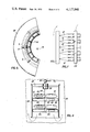
- FIGS. 5 and 6 show an embodiment in which the ribs 12 are connected to the shell 11 which is here rotatably mounted on an outer sleeve 40 into which the liquid passes through its upper end submerged in the clarifier tank.
- the motor 16 is mounted on struts 41 of the sleeve 40 and has hollow shaft 42 communicating with an oxygen distributor 43 and opening into a chamber 44 formed at the bottom of the rotor.
- the chamber 44 communicates with aerodynamically shaped vertical members 45 which function as radial vanes to displace the liquid outwardly, and in addition are formed with gas-permeable bodies 46, corresponding to the bodies 4 described in connection with FIG. 1.
- the aerodynamically shaped vanes 45 diverge radially outwardly as can be seen from FIG. 6.
- the shaft 42 can carry a gear 47 which meshes with a gear 48 on the strut 41, the latter, in turn, meshing with a ring gear 49 on the interior of the duct 11. Consequently, the duct 11 and the ribs 12 are rotated in the sense opposite the sense of rotation of members 45.
- the latter may carry horizontal ribs as shown in FIG. 7, the latter being interfitted alternatingly with the ribs 12.
- the duct 11 is provided with a distributor 50 supplied with oxygen and communicating, e.g. a tube 17, with the ribs 12.
- oxygen is fed into the gas by both sets of counterrotating ribs.
- the horizontal ribs of the inner rotor of the system of FIG. 7 is represented at 14.
- the ribs 14 are received between the ribs 12 and, to allow these ribs to clear one another during their rotations, the vanes 113 and 112a of the counterrotating rotors are set off to opposite sides of the ribs 12 and 14.
Landscapes
- Chemical & Material Sciences (AREA)
- Chemical Kinetics & Catalysis (AREA)
- Life Sciences & Earth Sciences (AREA)
- Engineering & Computer Science (AREA)
- Microbiology (AREA)
- Hydrology & Water Resources (AREA)
- Biodiversity & Conservation Biology (AREA)
- Environmental & Geological Engineering (AREA)
- Water Supply & Treatment (AREA)
- Organic Chemistry (AREA)
- Physical Or Chemical Processes And Apparatus (AREA)
- Vaporization, Distillation, Condensation, Sublimation, And Cold Traps (AREA)
- Structures Of Non-Positive Displacement Pumps (AREA)
- Aeration Devices For Treatment Of Activated Polluted Sludge (AREA)
- Gas Separation By Absorption (AREA)
Abstract
An apparatus for introducing gas, e.g. atmospheric oxygen, into a liquid such as waste water or sewage comprises a plurality of ribs of airfoil cross-section and forming venturi nozzles which are first constricted and then widened in the direction of liquid flow. The ribs are formed with minute passages for introducing the gas into the liquid perpendicular to the direction of liquid flow across the ribs.
Description
The present invention relates to an apparatus or device for introducing a gas into a liquid and, more particularly, to an apparatus for treating a liquid with the gas, e.g. to dissolve the gas or a component thereof into the liquid.
Apparatus for treating a liquid with the gas can have many utilities and of particularly great interest at the present time are systems for dissolving oxygen in liquids such as waste water as part of a purification thereof.
Waste-water purification systems may involve the aerobic decomposition of organic components of waste water, e.g. in an activated sludge tank, with the result that a purified decantate can be removed free from toxic or noxious components. Of course, it is also interesting to introduce other gases, such as carbon dioxide, into water for various purposes, to dissolve ammonia in water and, in general, treat a liquid phase with gas phase.
A wide variety of techniques have been developed for this purpose ranging from the simple injection of the gas into a stationary body of water through so-called aeration stones, spraying the liquid into the gas, rapidly mixing liquid in such a manner as to draw gas into it, etc.
A particularly advantageous approach has been described in the German published application (Offenlegungschrift) DT-OS 2,223,460 in which the liquid is pumped through a multiplicity of passages into which capillary ribs open to introduce the gas. The result is a highly efficient gas diffusion system in which the liquid streams passing through the channels entrain the gas in the form of small bubbles. The bubble size depends upon the velocity of the liquid stream flowing across the lateral opening of the capillary into the flow passage because the bubble is formed by a chearing at this opening.
When such a system is used for waste waters and other contaminant-containing liquid streams, the flow passages are readily blocked or obstructed and the necessary high velocities cannot be obtained.
Thus, while the system is highly efficient if satisfactory liquid velocities and flow rates can simultaneously be attained, it has not been found to be practical for many applications.
It is the principal object of the present invention to provide an apparatus for the mixing of a gas with a liquid which is economical to operate with respect to energy losses or consumption, is more effective as prior-art devices of the aforedescribed type and provides a highly efficient combination of the gas with the liquid.
Another object of the invention is to provide a system for the purposes described which is less prone to blocking or obstruction than the earlier systems, is particularly suited for the treatment of waste water, and which is free from other disadvantages characterizing gas-dispersing systems in finely divided form in a liquid phase.
These objects and others which will become hereinafter apparent are attained, in accordance with the present invention, by providing a plurality of gas-distribution ribs with aerodynamic or airfoil profiles across which the liquid flows and which are provided along a surface of the aerodynamic or streamlined ribs with passage-forming means for feeding the gas into the liquid generally transversely to its flow direction. Advantageously, the profiles of adjacent ribs define between them venturi nozzles.
The term "venturi nozzle" is here used to define a passage which is initially (in the direction of flow of the liquid) converges relatively sharply to a minimum spacing and thereafter widens more slowly. Preferably the gas-discharging means is disposed immediately upstream of this last divergence.
A gap between the ribs shaped as a venturi nozzle in the manner described, with the gas-discharging means disposed ahead of the divergence, permits the liquid to suck the gas from the gas outlet passages and shear the gas at high velocity in the constriction from the gas flow in the form of especially fine bubbles.
The gas is sucked by the liquid from the passages by the venturi effect.
The gas discharge means can be a perforated plate or a porous body, e.g. an aeration stone made of any convenient material, e.g. sintered particles of metal, ceramic or synthetic resin, which is perferably disposed on an upper or lower surface of the rib. The ribs can be oriented horizontally.
According to a feature of the invention, the ribs are connected with a source of gas, e.g. oxygen or atmospheric air whose oxygen is to be dissolved in waste water by pipes feeding the group of ribs, the ribs being hollow to distribute the gas to the several gas-permeable members forming the discharge means. Alternatively, the ribs can communicate with a common chamber supply with the gas or may be provided with a manifold which feeds the gas to them.
The bubbles sheared by the high-velocity liquid in the narrowest part of each constriction are entrained by the liquid flowing between the ribs and are thereafter dispersed in the remaining body of liquid. Because of the relatively low volume of each bubble, the bubbles rapidly dissolve. The divergence at the end of the flow passage between each pair of ribs acts as a diffuser in which velocity is transformed again into pressure after pressure has been transformed into an increased velocity in the narrowest part of the constriction thereby minimizing the total energy consumption of the device.
The displacement of the liquid can be effected by a submerged pump adapted to drive the liquid through the gaps between the ribs of the gas distributor. In this case, it is advantageous to provide the gas distributor in the form of a grid of such ribs of the outlet of a nozzle or duct traversed by the liquid and having the submerged pump at the intake end.
Of course, nozzles can be provided to inject the carrier liquid into the gap between the ribs so that the displacement of the larger body of liquid is effected in accordance with ejector principles.
According to another feature of the invention, the ribs are formed as annular or ring-shaped members, e.g. as horizontal annular hollow discs at the end of a vertical pipe and are spaced along the axis thereof to provide radial venturi gaps. The entire assembly can be received in a sewage clarification tank and a pump can be provided to circulate water axially downwardly through the duct and radially outwardly through the annular ribs.
According to the invention we can make use of a propeller pump and a radial pump whose rotor is disposed within the space surrounded by the annular ribs can also be employed. Thus the water circulation device can be used to circulate the contents of the tank as well as aerate the latter.
The pump motor can be disposed above the liquid level, the shaft of the pump extending vertically into the assembly as described.
According to another aspect of the invention, a pump rotor or impeller can be formed from a plurality of radial pump wheels which can alternate with annular ribs of the type described and furthermore the annular ribs and the radial pump wheels can be rotatable counter to one another, i.e. in opposite senses.
Such an arrangement not only permits a more effective circulation of liquid downwardly and outwardly through the unit within the clarifier vessel but also increases the relative velocity between the liquid and the ribs, thereby increasing the shearing effect and reducing the diameter of the gas bubbles which are formed. One or more ribs in any of the embodiments described can be provided with one or more vibrators to increase the relative velocity of the liquid and the ribs. The brief accelerations imparted by the vibrator to the ribs has been found to produce especially small bubbles and permits the flow velocity of the liquid to be reduced without detrimentally affecting the overall efficiency of the device.
Especially high relative velocities are obtained when one or more ribs are provided as multiblade propellers cooperating with fixed ribs. The ribs can also be the liquid displacing vanes of a radial pump.
The invention is not only applicable to dissolution of gases in liquids but may be used in addition for the separation of liquids and solid particles by flotation, i.e. systems in which gas bubbles are generated to adhere to solid particles.
The above and other objects, features and advantages of the present invention will become more readily apparent from the following description, reference being made to the accompanying drawing in which:
FIG. 1 is a vertical section through a plurality of horizontally disposed ribs, drawn to an enlarged scale and illustrating diagrammatically the principles of the present invention;
FIG. 2 is an axial cross section through an apparatus according to the present invention, also diagrammatically represented;
FIG. 3 is a vertical axial cross-sectional view through a gas-dispersing device for a waste water treatment plant;
FIG. 4 is a section similar to FIG. 3 through another device for this purpose, also according to the invention;
FIG. 5 is a view similar to FIG. 3 but illustrating another embodiment of the invention;
FIG. 6 is a section taken along the line VI--VI of FIG. 5; and
FIG. 7 is a vertical section through another embodiment.
FIG. 1 shows three ribs in schematic cross section forming a grid of a gas-dispersing device, e.g. of the type shown in FIG. 2. The ribs 1, 2 and 3 are of aerodynamic profile and thus each has a streamlined or rounded upstream end as represented at 1a, 2a, 3a against which the oncoming stream of liquid represented by the arrow L impinges.
The upper and lower surface 1b and 1c, 2b and 2c, 3b and 3c define a pair of flow passages represented generally at 1d and 2d respectively. Each of these passages initially converges in a zone a, remains constant over a zone b and diverges over a zone c, the divergence of zone c being less rigid than the convergence in the zone a. The zone b represents the maximum constriction of the flow passages 1d and 2d. The flow passages 1d and 2d thus constitute venturi nozzles which tend to draw gas into the liquid from the passages in a block 4 disposed along the upper and lower surfaces of each rib substantially over a major portion of the width of the zone b. The blocks 4 are composed of sintered metals, ceramic or synthetic resin and are permeable to gas so as to effectively have a multiplicity of capillary passages from which the gas can be sucked by the venturi effect. Because of the constricting nature of the venturi nozzle, the liquid has a maximum flow velocity in the zone b.
The upper and lower walls of each rib 1, 2, 3 is provided with seats 1e, 2e and 4e in which the gas permeable member 4 is received.
As the gas is torn from the passages of its permeable block 4, it is entrained with a liquid phase and dispersed into surrounding liquid at the downstream side d of the device. Gas is supplied to the ribs via a line represented diagrammatically at 5. It will be apparent that the ribs extend horizontally so that the venturi nozzles are generally flat and horizontal and are not readily obstructed by contaminants contained in the waste water or sewage.
FIG. 2 illustrates a gas-dispersal device particularly adapted to enriching waste water or sewage with oxygen or for treating natural water, e.g. drinking water with oxygen by aeration. In this embodiment a multiplicity of ribs 6, generally similar to the ribs 1-3 and operating in accordance with the same principles, form a grid work 6a at the downstream side of duct 7 which has intake 7a and an outlet 7b. Between the small-cross section intake 7a and the large-cross section outlet 7b, the duct 7 diverges as represented at 7c.
A submersible pump 8 is mounted coaxially via strut 7d in the intake 7a which is provided with a large-mesh grid 10 of a basket shape to prevent entry of objects which may interfere with the pumping operation. The pump 8 has a propeller-type 8a which drives the liquid in the direction of arrow 8b.
Downstream of the pump 8, 8a but upstream of the grid 6a, the duct 7 is provided with guide plates 9 to reduce turbulence and maintain approximately laminar flow of the liquid through the grid 6a. The latter is mounted by a vertical rib 6b upon the duct 7 and can be supplied with oxygen via the line 5 previously described. The vertical rib 6b can be mounted elastically at 6c and 6d upon the wall of the duct 7 and can be connected to a vibrator 6e to produce oscillations of the ribs transverse to the direction of liquid flow as represented by the arrow e. The ribs 6 disperse the gas into the liquid as the latter flows in the direction of arrow 8b through the device in the manner described in FIG. 1.
The assembly of FIG. 2 can be carried on a support, represented diagrammatically at 7e enabling it to be rotated about a vertical axis or entrained in a circular path about a vertical axis in the clarifier tank in which it is disposed for aerating the sewage.
FIG. 3 shows, in diagrammatic cross section another embodiment of the invention in which a vertically extending duct 11 is submerged in a clarifier tank and is provided with a plurality of vertically spaced horizontal annular ribs 12 as described for the ribs 1 through 3 previously. The ribs 12 are supported on vertical struts 12a suspended from an outwardly extending flange 11a of the duct 11. A pipe 17, connected to an oxygen source, communicates with all of the ribs and interconnects them to enable them to disperse in the liquid. The ribs are formed with the gas-permeable bodies 4 mentioned previously and define radially extending venturi gaps in the manner also described above.
A motor 16 has a shaft 15 carrying a rotor 15a which is formed with a plurality of angularly spaced struts 15b attaching a downwardly converging shell 15c to this shaft 15. On this shell 15c there are a multiplicity of vertical vanes 13 which form a radial pump forcing the liquid outwardly between the ribs 12. The liquid is drawn downwardly over the top of the duct 11 as shown by the arrows in FIG. 3. This arrangement operates in the manner described with respect to FIG. 2 except that the flow of liquid is radial with respect to the pump rather than axial.
In FIG. 4 we have shown an arrangement in which a vertical duct 25 is disposed within the clarifier tank 26 and is open at its upper and lower ends therein. The upper end carries, via ribs 27, a motor 28 whose shaft 29 is hollow and transmits oxygen from a distributor 30 to a plurality of multiblade propellers 31 and 32 of aerodynamic configuration and provided on their upper and lower surfaces with porous members 33 each shown at 4 in FIG. 1.
The propeller blades are hollow and disperse the gas in the liquid as previously described. The blades cooperate with fixed vanes 34, also of aerodynamic profile, and supplied with gas from the shaft 29 via lateral openings therein. As each blade sweeps over a respective vane it defines a rearwardly diverging venturi passage therewith with the general effect described in connection with FIGS. 1 and 2, the liquid being displaced generally through duct 25 as shown by the arrows.
FIGS. 5 and 6 show an embodiment in which the ribs 12 are connected to the shell 11 which is here rotatably mounted on an outer sleeve 40 into which the liquid passes through its upper end submerged in the clarifier tank. The motor 16 is mounted on struts 41 of the sleeve 40 and has hollow shaft 42 communicating with an oxygen distributor 43 and opening into a chamber 44 formed at the bottom of the rotor. The chamber 44 communicates with aerodynamically shaped vertical members 45 which function as radial vanes to displace the liquid outwardly, and in addition are formed with gas-permeable bodies 46, corresponding to the bodies 4 described in connection with FIG. 1. The aerodynamically shaped vanes 45 diverge radially outwardly as can be seen from FIG. 6. The shaft 42 can carry a gear 47 which meshes with a gear 48 on the strut 41, the latter, in turn, meshing with a ring gear 49 on the interior of the duct 11. Consequently, the duct 11 and the ribs 12 are rotated in the sense opposite the sense of rotation of members 45. The latter may carry horizontal ribs as shown in FIG. 7, the latter being interfitted alternatingly with the ribs 12. The duct 11 is provided with a distributor 50 supplied with oxygen and communicating, e.g. a tube 17, with the ribs 12. Thus oxygen is fed into the gas by both sets of counterrotating ribs. The horizontal ribs of the inner rotor of the system of FIG. 7 is represented at 14. The ribs 14 are received between the ribs 12 and, to allow these ribs to clear one another during their rotations, the vanes 113 and 112a of the counterrotating rotors are set off to opposite sides of the ribs 12 and 14.
Claims (2)
1. A device for dispersing a gas in a liquid in the aeration of sewage in a clarifier tank, comprising a plurality of aerodynamically spaced ribs defining between them venturi passages, means for inducing a flow of liquid through said passages, said passages progressively converging from an upstream side to a constricted portion and thereafter diverging to a downstream side of the respective passage, and gas-permeable means along at least one surface of each of said ribs bounding a respective one of said passages in the region of the respective constriction for feeding gas to the liquid in a direction substantially perpendicular to the direction of liquid flow through the respective passage, a vertical duct in said tank open at its upper end and formed at its lower end with said ribs, said ribs being axially spaced horizontal rings, said means for displacing said liquid through said passages including an axial intake, radial outflow pump having a rotor surrounded by said rings for displacing liquid between them.
2. The device defined in claim 1 wherein said rotor is formed with hollow aerodynamically shaped ribs formed with gas-permeable surfaces, said device further comprising means for supplying gas to said rotor.
Priority Applications (1)
| Application Number | Priority Date | Filing Date | Title |
|---|---|---|---|
| US05/895,641 US4193950A (en) | 1975-07-04 | 1978-04-12 | Apparatus for introducing gas into a liquid |
Applications Claiming Priority (2)
| Application Number | Priority Date | Filing Date | Title |
|---|---|---|---|
| DE19752530050 DE2530050A1 (en) | 1975-07-04 | 1975-07-04 | DEVICE FOR GASIFICATION OF LIQUIDS |
| DE2530050 | 1975-07-04 |
Related Child Applications (1)
| Application Number | Title | Priority Date | Filing Date |
|---|---|---|---|
| US05/895,641 Continuation-In-Part US4193950A (en) | 1975-07-04 | 1978-04-12 | Apparatus for introducing gas into a liquid |
Publications (1)
| Publication Number | Publication Date |
|---|---|
| US4117048A true US4117048A (en) | 1978-09-26 |
Family
ID=5950730
Family Applications (1)
| Application Number | Title | Priority Date | Filing Date |
|---|---|---|---|
| US05/702,052 Expired - Lifetime US4117048A (en) | 1975-07-04 | 1976-07-02 | Apparatus for introducing gas into a liquid |
Country Status (12)
| Country | Link |
|---|---|
| US (1) | US4117048A (en) |
| JP (1) | JPS5222163A (en) |
| AT (1) | AT345198B (en) |
| AU (1) | AU1560676A (en) |
| BE (1) | BE843672A (en) |
| CH (1) | CH604864A5 (en) |
| DE (1) | DE2530050A1 (en) |
| DK (1) | DK300776A (en) |
| ES (1) | ES449559A1 (en) |
| FR (1) | FR2315984A1 (en) |
| NL (1) | NL7607333A (en) |
| SE (1) | SE7606878L (en) |
Cited By (21)
| Publication number | Priority date | Publication date | Assignee | Title |
|---|---|---|---|---|
| US4193950A (en) * | 1975-07-04 | 1980-03-18 | Linde Aktiengesellschaft | Apparatus for introducing gas into a liquid |
| EP0015050A1 (en) * | 1979-01-29 | 1980-09-03 | General Signal Corporation | Fluids mixing apparatus |
| US4290885A (en) * | 1977-12-22 | 1981-09-22 | Dochan Kwak | Aeration device |
| US4399028A (en) * | 1982-06-14 | 1983-08-16 | The Black Clawson Company | Froth flotation apparatus and method |
| US4521349A (en) * | 1983-01-20 | 1985-06-04 | A. R. Wilfley And Sons, Inc. | Fluid diffuser for gases and liquids |
| US4717515A (en) * | 1985-04-29 | 1988-01-05 | Wilfley Weber, Inc. | Apparatus for dispersing fluids in liquids |
| US4961882A (en) * | 1988-06-23 | 1990-10-09 | Exxon Research And Engineering Company | Fine bubble generator and method |
| US5051213A (en) * | 1983-08-16 | 1991-09-24 | Weske John R | Method and apparatus for mixing fluids |
| US5102104A (en) * | 1990-03-05 | 1992-04-07 | U.S. Gold Corporation | Biological conversion apparatus |
| US5122312A (en) * | 1991-03-05 | 1992-06-16 | Mott Metallurgical Corporation | Bubble injection system |
| JPH0491798U (en) * | 1990-12-21 | 1992-08-10 | ||
| US5143543A (en) * | 1991-08-23 | 1992-09-01 | U.S. Gold Corporation | Biological conversion method |
| US5591328A (en) * | 1990-11-23 | 1997-01-07 | Atomaer Pty. Ltd. | Gas particle formation |
| US5925293A (en) * | 1996-10-04 | 1999-07-20 | General Signal Corporation | Mixer sparging apparatus |
| US6398195B1 (en) * | 1998-04-10 | 2002-06-04 | Grt, Inc. | Method of and apparatus for producing sub-micron bubbles in liquids and slurries |
| WO2005079963A2 (en) * | 2004-01-20 | 2005-09-01 | Venetec Gmbh | Device for the continuous production of substances containing finely dispersed gas |
| US20080145274A1 (en) * | 2006-12-14 | 2008-06-19 | Sasan Habibi-Naini | Porous Metering Device |
| US20110008026A1 (en) * | 2008-03-05 | 2011-01-13 | Campbell Mark E | Molecular heater and method of heating fluids |
| ITUA20164423A1 (en) * | 2016-05-27 | 2017-11-27 | Teda Sas Di Cristina Soranzo & C | SELF-SPRAYING EXTERNAL MIXER FOR AIR DISSOLUTION / MIXING IN BIOLOGICAL OXIDATION TANKS |
| US20180186669A1 (en) * | 2015-07-09 | 2018-07-05 | Ariel Scientific Innovations Ltd. | Methods and devices for performing reactions |
| US20210394134A1 (en) * | 2020-06-23 | 2021-12-23 | Noritz Corporation | Premixing device and combustion device equipped with the premixing device |
Families Citing this family (3)
| Publication number | Priority date | Publication date | Assignee | Title |
|---|---|---|---|---|
| PL129048B1 (en) * | 1980-05-31 | 1984-03-31 | Okregowa Spoldzielnia Mleczars | Method of deeply aerating waste waters and apparatus therefor |
| DE4135878A1 (en) * | 1991-10-31 | 1993-05-06 | Helmut Dipl.-Phys. 6759 Hohenoellen De Gehm | Extended liq. gas phase boundary surface prodn - by feeding fluid flow in conduit over displacement body with aerofoil shape and 2nd is introduced by injector located in body at area of largest cross=section |
| DE4224911A1 (en) * | 1992-07-09 | 1994-01-13 | Tech Resources Pty Ltd | Aerator, esp. for provision of oxygen@ to biological ore extn. liq. - contains of vertical duct with throat section which has elongated shape and is provided with means for introducing required gas |
Citations (9)
| Publication number | Priority date | Publication date | Assignee | Title |
|---|---|---|---|---|
| US1250303A (en) * | 1915-12-04 | 1917-12-18 | William E Greenawalt | Flotation apparatus. |
| GB412842A (en) * | 1932-11-22 | 1934-07-05 | Julius Gosda | Pipe system for aeration and ventilation of liquids, especially of fermenting worts in the manufacture of yeast, spirit, vinegar and the like |
| US2144385A (en) * | 1935-03-18 | 1939-01-17 | Advance Engineering Company | Sewage treatment apparatus |
| US2221346A (en) * | 1938-07-13 | 1940-11-12 | Chicago Pump Co | Air diffusing means |
| US2708571A (en) * | 1951-05-29 | 1955-05-17 | Industrikemiska Ab | Method and apparatus for contacting gases and liquids |
| US2719032A (en) * | 1950-08-23 | 1955-09-27 | Ruhrchemie Ag | Treatment of gases with washing liquids |
| US3043433A (en) * | 1961-05-17 | 1962-07-10 | Singer Oscar Caton | Sewage treatment plant |
| US3133130A (en) * | 1959-09-24 | 1964-05-12 | Dorr Oliver Inc | Treatment tank for aerobically purifying waste liquids |
| US3947359A (en) * | 1973-03-06 | 1976-03-30 | Alec Hibburd Laurie | Aeration and mixing of liquids |
Family Cites Families (4)
| Publication number | Priority date | Publication date | Assignee | Title |
|---|---|---|---|---|
| DE1557051A1 (en) * | 1966-08-10 | 1969-08-28 | Eta Corp | Stirring or mixing device, in particular ventilation device for clarification systems |
| US3489396A (en) * | 1968-03-14 | 1970-01-13 | Paul D Aragon | Stream water aerator |
| DE2143518C2 (en) * | 1971-08-31 | 1982-11-25 | Versuchsanstalt Fuer Binnenschiffbau E.V., 4100 Duisburg | Oxygen enrichment appts. for surface waters - includes perforated ring in slipstream of propeller of shallow bottom boat |
| DE2232514A1 (en) * | 1972-07-03 | 1974-01-24 | Messerschmitt Boelkow Blohm | DEVICE FOR VENTILATION OF WATERS |
-
1975
- 1975-07-04 DE DE19752530050 patent/DE2530050A1/en not_active Withdrawn
- 1975-12-15 AT AT950275A patent/AT345198B/en not_active IP Right Cessation
-
1976
- 1976-06-09 CH CH728976A patent/CH604864A5/xx not_active IP Right Cessation
- 1976-06-16 SE SE7606878A patent/SE7606878L/en unknown
- 1976-06-28 JP JP7699976A patent/JPS5222163A/en active Pending
- 1976-06-30 FR FR7620023A patent/FR2315984A1/en active Granted
- 1976-07-01 BE BE168543A patent/BE843672A/en unknown
- 1976-07-02 US US05/702,052 patent/US4117048A/en not_active Expired - Lifetime
- 1976-07-02 DK DK300776A patent/DK300776A/en not_active Application Discontinuation
- 1976-07-02 NL NL7607333A patent/NL7607333A/en unknown
- 1976-07-03 ES ES449559A patent/ES449559A1/en not_active Expired
- 1976-07-05 AU AU15606/76A patent/AU1560676A/en not_active Expired
Patent Citations (9)
| Publication number | Priority date | Publication date | Assignee | Title |
|---|---|---|---|---|
| US1250303A (en) * | 1915-12-04 | 1917-12-18 | William E Greenawalt | Flotation apparatus. |
| GB412842A (en) * | 1932-11-22 | 1934-07-05 | Julius Gosda | Pipe system for aeration and ventilation of liquids, especially of fermenting worts in the manufacture of yeast, spirit, vinegar and the like |
| US2144385A (en) * | 1935-03-18 | 1939-01-17 | Advance Engineering Company | Sewage treatment apparatus |
| US2221346A (en) * | 1938-07-13 | 1940-11-12 | Chicago Pump Co | Air diffusing means |
| US2719032A (en) * | 1950-08-23 | 1955-09-27 | Ruhrchemie Ag | Treatment of gases with washing liquids |
| US2708571A (en) * | 1951-05-29 | 1955-05-17 | Industrikemiska Ab | Method and apparatus for contacting gases and liquids |
| US3133130A (en) * | 1959-09-24 | 1964-05-12 | Dorr Oliver Inc | Treatment tank for aerobically purifying waste liquids |
| US3043433A (en) * | 1961-05-17 | 1962-07-10 | Singer Oscar Caton | Sewage treatment plant |
| US3947359A (en) * | 1973-03-06 | 1976-03-30 | Alec Hibburd Laurie | Aeration and mixing of liquids |
Cited By (27)
| Publication number | Priority date | Publication date | Assignee | Title |
|---|---|---|---|---|
| US4193950A (en) * | 1975-07-04 | 1980-03-18 | Linde Aktiengesellschaft | Apparatus for introducing gas into a liquid |
| US4290885A (en) * | 1977-12-22 | 1981-09-22 | Dochan Kwak | Aeration device |
| EP0015050A1 (en) * | 1979-01-29 | 1980-09-03 | General Signal Corporation | Fluids mixing apparatus |
| US4231974A (en) * | 1979-01-29 | 1980-11-04 | General Signal Corporation | Fluids mixing apparatus |
| US4399028A (en) * | 1982-06-14 | 1983-08-16 | The Black Clawson Company | Froth flotation apparatus and method |
| US4521349A (en) * | 1983-01-20 | 1985-06-04 | A. R. Wilfley And Sons, Inc. | Fluid diffuser for gases and liquids |
| US5051213A (en) * | 1983-08-16 | 1991-09-24 | Weske John R | Method and apparatus for mixing fluids |
| US4717515A (en) * | 1985-04-29 | 1988-01-05 | Wilfley Weber, Inc. | Apparatus for dispersing fluids in liquids |
| US4961882A (en) * | 1988-06-23 | 1990-10-09 | Exxon Research And Engineering Company | Fine bubble generator and method |
| US5102104A (en) * | 1990-03-05 | 1992-04-07 | U.S. Gold Corporation | Biological conversion apparatus |
| US5591328A (en) * | 1990-11-23 | 1997-01-07 | Atomaer Pty. Ltd. | Gas particle formation |
| JPH0491798U (en) * | 1990-12-21 | 1992-08-10 | ||
| JPH0642796Y2 (en) * | 1990-12-21 | 1994-11-09 | 阪神動力機械株式会社 | Submersible mechanical aerator |
| US5122312A (en) * | 1991-03-05 | 1992-06-16 | Mott Metallurgical Corporation | Bubble injection system |
| US5143543A (en) * | 1991-08-23 | 1992-09-01 | U.S. Gold Corporation | Biological conversion method |
| US5925293A (en) * | 1996-10-04 | 1999-07-20 | General Signal Corporation | Mixer sparging apparatus |
| US6398195B1 (en) * | 1998-04-10 | 2002-06-04 | Grt, Inc. | Method of and apparatus for producing sub-micron bubbles in liquids and slurries |
| WO2005079963A2 (en) * | 2004-01-20 | 2005-09-01 | Venetec Gmbh | Device for the continuous production of substances containing finely dispersed gas |
| WO2005079963A3 (en) * | 2004-01-20 | 2006-03-02 | Venetec Gmbh | Device for the continuous production of substances containing finely dispersed gas |
| US20080145274A1 (en) * | 2006-12-14 | 2008-06-19 | Sasan Habibi-Naini | Porous Metering Device |
| US20110008026A1 (en) * | 2008-03-05 | 2011-01-13 | Campbell Mark E | Molecular heater and method of heating fluids |
| US8532474B2 (en) * | 2008-03-05 | 2013-09-10 | Mark E. Campbell | Molecular heater and method of heating fluids |
| US20180186669A1 (en) * | 2015-07-09 | 2018-07-05 | Ariel Scientific Innovations Ltd. | Methods and devices for performing reactions |
| US10745305B2 (en) * | 2015-07-09 | 2020-08-18 | Ariel Scientific Innovations Ltd. | Methods and devices for performing reactions |
| ITUA20164423A1 (en) * | 2016-05-27 | 2017-11-27 | Teda Sas Di Cristina Soranzo & C | SELF-SPRAYING EXTERNAL MIXER FOR AIR DISSOLUTION / MIXING IN BIOLOGICAL OXIDATION TANKS |
| US20210394134A1 (en) * | 2020-06-23 | 2021-12-23 | Noritz Corporation | Premixing device and combustion device equipped with the premixing device |
| US11819811B2 (en) * | 2020-06-23 | 2023-11-21 | Noritz Corporation | Premixing device and combustion device equipped with the premixing device |
Also Published As
| Publication number | Publication date |
|---|---|
| CH604864A5 (en) | 1978-09-15 |
| AT345198B (en) | 1978-09-11 |
| ATA950275A (en) | 1977-12-15 |
| DK300776A (en) | 1977-01-05 |
| BE843672A (en) | 1976-11-03 |
| FR2315984B1 (en) | 1980-04-30 |
| NL7607333A (en) | 1977-01-06 |
| AU1560676A (en) | 1978-01-12 |
| FR2315984A1 (en) | 1977-01-28 |
| JPS5222163A (en) | 1977-02-19 |
| DE2530050A1 (en) | 1977-01-27 |
| SE7606878L (en) | 1977-01-05 |
| ES449559A1 (en) | 1977-08-01 |
Similar Documents
| Publication | Publication Date | Title |
|---|---|---|
| US4117048A (en) | Apparatus for introducing gas into a liquid | |
| US4193950A (en) | Apparatus for introducing gas into a liquid | |
| US3846516A (en) | Aerator device and method | |
| US4210534A (en) | Multiple stage jet nozzle and aeration system | |
| US4844843A (en) | Waste water aerator having rotating compression blades | |
| US3814396A (en) | Aeration apparatus | |
| EP1001840B1 (en) | Gas-liquid venturi mixer | |
| US4224158A (en) | Aeration system and method with tapered nozzle | |
| JPS5920373B2 (en) | Method and device for increasing the oxygen content of water | |
| EP2445618B1 (en) | Apparatus and method for introducing a gas into a liquid | |
| KR20000047823A (en) | System for the dissolution of gas | |
| FI96388B (en) | Gas solution and method | |
| US3910838A (en) | Method and apparatus for the purification of aqueous effluent | |
| KR100274386B1 (en) | Reactor | |
| JP2002052330A (en) | Gas and liquid supply device | |
| JPH11333491A (en) | Microbubble jet water purifying apparatus | |
| JPH05253592A (en) | Stirring aerator | |
| JP3747261B2 (en) | Dispersion method of gas-liquid mixed fluid and dispersion device used in the method | |
| JPS63209791A (en) | Aerator | |
| IE47685B1 (en) | Aerator | |
| JP6345545B2 (en) | Aeration stirrer | |
| JP3582036B2 (en) | Gas-liquid contact device | |
| JP6345546B2 (en) | Power-saving aeration stirrer | |
| WO2017124128A1 (en) | Jet aeration and mixing nozzle | |
| PL183241B1 (en) | Apparatus for mixing air with water in a water purifier |