US4046399A - Electrohydraulic system for towed vehicle - Google Patents
Electrohydraulic system for towed vehicle Download PDFInfo
- Publication number
- US4046399A US4046399A US05/628,967 US62896775A US4046399A US 4046399 A US4046399 A US 4046399A US 62896775 A US62896775 A US 62896775A US 4046399 A US4046399 A US 4046399A
- Authority
- US
- United States
- Prior art keywords
- valve
- assembly
- switching
- pair
- solenoid
- Prior art date
- Legal status (The legal status is an assumption and is not a legal conclusion. Google has not performed a legal analysis and makes no representation as to the accuracy of the status listed.)
- Expired - Lifetime
Links
Images
Classifications
-
- B—PERFORMING OPERATIONS; TRANSPORTING
- B60—VEHICLES IN GENERAL
- B60D—VEHICLE CONNECTIONS
- B60D1/00—Traction couplings; Hitches; Draw-gear; Towing devices
- B60D1/58—Auxiliary devices
- B60D1/62—Auxiliary devices involving supply lines, electric circuits, or the like
-
- Y—GENERAL TAGGING OF NEW TECHNOLOGICAL DEVELOPMENTS; GENERAL TAGGING OF CROSS-SECTIONAL TECHNOLOGIES SPANNING OVER SEVERAL SECTIONS OF THE IPC; TECHNICAL SUBJECTS COVERED BY FORMER USPC CROSS-REFERENCE ART COLLECTIONS [XRACs] AND DIGESTS
- Y10—TECHNICAL SUBJECTS COVERED BY FORMER USPC
- Y10S—TECHNICAL SUBJECTS COVERED BY FORMER USPC CROSS-REFERENCE ART COLLECTIONS [XRACs] AND DIGESTS
- Y10S60/00—Power plants
- Y10S60/911—Fluid motor system incorporating electrical system
Definitions
- This invention relates to the field of towed vehicles which have many hydraulically operated functions and in particular, an electrohydraulic system for those hydraulic functions.
- Towed vehicles are well known in the art in which specific functions are carried out hydraulically.
- towed farm vehicles may have from three to eight and even more functions each of which is hydraulically powered.
- the "Stackeze” made by the Haybuster Corporation handles hay and has five functions and thus requires a control valve assembly with five hydraulic control valves and five control handles.
- Another towed farm vehicle, the "Mark 660 Potato Harvester” made by the Lockwood Corporation may have up to eight functions thus requiring at least one control valve assembly comprised of eight hydraulic control valves and eight control handles.
- control valve assembly may be secured to the towed vehicle.
- an operator additional to the tractor operator is required to ride on the towed vehicle in order to actuate the control handles.
- control valve assembly may be unbolted from the towed vehicle and attached to the tractor so that the control handles may be close to the tractor operator.
- it has been attempted to position the control valve assembly convenient to the tractor operator so that he could not only drive the tractor but also operate the controls of the valve assembly.
- a towed vehicle having a frame and hydraulic functions powered by a plurality of hydraulic devices to be controlled.
- An electrohydraulic valve assembly is hydraulically coupled to the hydraulic devices and is rigidly secured to the frame of the towed vehicle.
- a switching assembly having a plurality of switches is adapted for electrically switching the valve assembly.
- An electrical cable is coupled between the switching assembly and the valve assembly secured to the vehicle frame. The switching assembly is disposed within the cab to allow easy access of the plurality of switches to the operator of the tractor while avoiding hydraulic oil lines and valves within the cab and at the same time allowing the towed vehicle to be easily disconnected from the tractor.
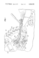
- FIG. 1 shows a portion of a towed vehicle and a tractor pulling it
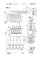
- FIG. 2 illustrates in more detail the electrohydraulic valve assembly and switching assembly shown in FIG. 1;
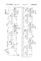
- FIG. 3 schematically illustrates the individual switches of the switching assembly as coupled to the electrohydraulic valve assembly of FIGS. 1 and 2;
- FIG. 4 schematically illustrates the hydraulic circuit of the electrohydraulic valve assembly of FIGS. 1-3.
- FIGS. 5 and 6 illustrates in detail a normally open solenoid valve and a closed center screw adaptor shown in FIGS. 1-4.
- FIG. 1 there is shown a tractor 10 pulling a towed vehicle 12 having an electrohydraulic valve system including a valve assembly 15 which operates and controls all of the hydraulically powered functions of the towed vehicle.
- Towed vehicle 12 may be any conventional towed farm vehicle such as "Stackeze 1600" which picks up hay by means of a hay pick up 18, compresses the hay and effectively forms the compressed hay into a stack on the rear portion of vehicle 12 (not shown). Towed vehicle 12 accomplishes its overall stacking operation by means of five hydraulic functions. Thus, valve assembly 15 requires five valve circuits 15a-15d for controlling the five hydraulic functions. As illustrated, vehicle 12 has an elongated frame 20, a hitch bar 22 secured to frame 20 and power apparatus 24 for receiving the power take off (PTO) of tractor 10.
- PTO power take off
- Tractor 10 is a conventional farm tractor having a rear axle 26 and rear wheel 28. Tractor 10 may have a fully enclosed cab 30 or body which provides the tractor operator with protection from noise, dirt, shock, vibration, heat and cold as well as dust, wind and other adverse weather conditions. Thus, the windows, doors and body of cab 30 are tightly sealed and the atmosphere of the cab is pressurized and filtered. It is in this way that dust and powdery snow are kept from the cab's interior. Further, a heater and an air conditioner allow the operator to adjust the cab's temperature and humidity. With the further addition of padding and vibration protection, there is formed a controlled environment for the operator.
- Tractor 10 includes a conventional hitch 32 for attachment to hitch bar 22 and a draw bar 34 is helpful with wind-span towed equipment. Further, tractor 10 has a PTO assembly comprising a power shaft 36 which is coupled to assembly 24 of towed vehicle 12. In addition, tractor 10 has a conventional hydraulic remote cylinder outlet 38 coupled to a pump line 40 and a drain line 41.
- valve assembly 15 As shown in FIGS. 1, 2 and 4, pump line or hose 40 and drain line or hose 41 are connected to electrohydraulic valve assembly 15 which is secured to an upper portion of frame 20 as illustrated. Valve assembly 15 is coupled by lines and hoses in conventional manner to the hydraulic cylinders (not shown) of towed vehicle 12 which operate the five functions of unload, dump, pick up, swing and boom lift. It will be understood that these hydraulic functions are examples of hydraulic functions which could be used on a towed vehicle.
- Valve assembly 15 is controlled by electric switch assembly 44 which is not secured to the towed vehicle but is mounted within cab 20.
- assembly 44 may be formed of a rectangular housing bolted within the cab in a position where it would be most comfortable for actuation by the tractor operator.
- a connector 46 leads to a cable 48 which extends below the assembly through cab 30 and terminates in a connector assembly 50 at the rear of tractor 10 adjacent outlet 38.
- a seal is used to plug the gap around cable 48 after it has been installed to maintain the integrity of cab 30.
- Assembly 50 receives a plug-in connector 51 which is coupled by means of a cable 52 to the valve assembly 15.
- Switch assembly 44 is grounded to the chassis or frame of tractor 10.
- the positive side (V+) of tractor battery 54 is coupled to assembly 44 and in conventional manner, the negative side of the battery is coupled to chassis ground. Since towed vehicle 12 may or may not have a ground connection to tractor 10, the ground for valve assembly 15 is returned by way of cables 52 and 48 to the chassis ground at switch assembly 44.
- switch assembly 44 may be releasably secured within the cab in the form of a wall mount with cable 48 being a flexible extension cable extending therefrom. In this way, assembly 44 may be moved anywhere in the cab. Further, cable 48 may itself directly extend to assembly 15 without the use of connectors 50, 51 and pass through a sealed opening in the cab. Accordingly, assembly 44 may then be removed from the cab and used in the cab of another tractor.
- Valve assembly 15 operates in the following manner under the control of switch assembly 44 as illustrated in FIGS. 2-4.
- Valve assembly 15 comprises a stacked valve assembly comprising solenoid valves 60-69 and pilot operated four way spool valves 70-74.
- valve assembly 15 comprises six valve sections 15a-f which have been stacked together. Each of the valve sections may comprise one or two solenoid valves and a spool valve. It is in this manner that the unitary valve assembly 5 may be easily mounted on towed vehicle 12 in the manner previously described. It will be understood that such a unitary assembly may be provided by means other than a stacked valve assembly such as a single casting within which all of the valves have been assembled.
- an hydraulic fluid pump in tractor 10 is indicated as pump 55 while the drain is indicated as reservoir 56. Accordingly, pump and drain lines 40, 41 from pump 55 and reservoir 56 are applied to assembly 15.
- valve section 15f which comprises a two stage valve 58a-b which operates as illustrated in FIG. 4 if tractor 10 uses an open center system. With such an open center system, valve assembly 15 requires a normally open condition as illustrated.
- valve 58a-b may be made normally closed and inoperable in the field by means of a screw adapter 88 shown in FIGS. 5, 6 and later described in detail.
- Valve 58a-b may be similar in operation and construction to a two stage valve shown and described in U.S. Pat. No. 3,799,497.
- Switches 80-84 are conventional spring centered double pole double throw switches in which the left switch sections actuates valve 58a while the right switch section actuates the solenoid valves of a respective valve section 15a-e.
- valve 70 With switch 80 maintained in the left position, pressure continues to be applied to line 76 until the switch is released and returns to its spring center position. Then, the coils of valves 58a and 60 are deenergized and valve 70 returns to its normal position in which all of its ports are blocked thereby maintaining the position of the unload cylinders connected to lines 76, 77.
- switch 80 In order to reverse the unload cylinders, switch 80 is moved to its illustrated right hand position. In the manner previously described, valve 58a-b is energized and moves to its closed position. In addition, solenoid valve 61 is energized and thus the right hand side of spool valve 70 is pressurized moving the cylinder to the left. Accordingly, the lines are reversed from that previously described with lines 77 having pressure applied thereto and tank is applied to line 76. This condition is maintained as long as switch 80 is maintained in the right hand position. At the time switch 80 is released to its spring center position, the unload cylinders are maintained in their position.
- valve sections 15b-e each operate in similar manner under the control of their respective switches 81-84. Since such operation is similar to that described for section 15a, it is not necessary to describe this operation in detail.
- valve 58a which is similar to the single stage normally opened solenoid operated valve shown in U.S. Pat. No. 3,765,644 and similar to the first stage valve shown in U.S. Pat. No. 3,799,497. Accordingly, with a screw 86 threadedly engaged in an upper section of housing or stack 87 a plunger 90 is not actuated and first stage 58a operates as a normally open valve for use with a tractor's open center system.
- valve 58a-b is made normally closed by means of the closed center screw adapter 88 shown in FIG. 6 which replaces screw 86.
- Screw adapter 88 comprises a normal screw threaded portion 88a and a reduced diameter extension 88b extending from the end of threaded portion 88a remote from head 88c.
- Extension 88b is effective to engage and move downwardly adjusting plunger 90 when screw adapter 88 is manually screwed downwardly into the upper section of stack 87.
- a spring 95 is disposed within cavity 91 and extends between the lower section of plunger 90 and an upper surface of armature 94. Accordingly, as plunger 90 moves downwardly, spring 95 is effective to downwardly bias armature 93.
- armature 93 applies downward pressure on a spring biased poppet 92 thus to close poppet plug 97 in orifice 98.
- Spring 95 is used to transmit the force from plunger 90 to armature 93 in order to avoid damage to plug 97 and orifice 98 in the event that screw adapter 88 is excessively screwed into stack 87.
- first stage 58a and thus second stage 58b may be made normally closed and inoperable in the field by means of replacing screw 86 with a screw adapter 88.
- switch assembly 44 may contain electronic subassemblies for purposes of automated control.
- certain functions may be programmed to operate in a desired sequence. When a bail reaches a certain height, another function and then another function may come into effect.
Landscapes
- Engineering & Computer Science (AREA)
- Transportation (AREA)
- Mechanical Engineering (AREA)
- Lifting Devices For Agricultural Implements (AREA)
- Fluid-Pressure Circuits (AREA)
Abstract
Description
Claims (14)
Priority Applications (1)
| Application Number | Priority Date | Filing Date | Title |
|---|---|---|---|
| US05/628,967 US4046399A (en) | 1975-11-05 | 1975-11-05 | Electrohydraulic system for towed vehicle |
Applications Claiming Priority (1)
| Application Number | Priority Date | Filing Date | Title |
|---|---|---|---|
| US05/628,967 US4046399A (en) | 1975-11-05 | 1975-11-05 | Electrohydraulic system for towed vehicle |
Publications (1)
| Publication Number | Publication Date |
|---|---|
| US4046399A true US4046399A (en) | 1977-09-06 |
Family
ID=24521049
Family Applications (1)
| Application Number | Title | Priority Date | Filing Date |
|---|---|---|---|
| US05/628,967 Expired - Lifetime US4046399A (en) | 1975-11-05 | 1975-11-05 | Electrohydraulic system for towed vehicle |
Country Status (1)
| Country | Link |
|---|---|
| US (1) | US4046399A (en) |
Cited By (20)
| Publication number | Priority date | Publication date | Assignee | Title |
|---|---|---|---|---|
| US4413685A (en) * | 1979-12-11 | 1983-11-08 | Gremelspacher Philip E | Planter implement with adjusting position-display apparatus and system thereof |
| US4662162A (en) * | 1984-02-29 | 1987-05-05 | Bettencourt Thomas S | Tomato harvester |
| US4679469A (en) * | 1984-07-10 | 1987-07-14 | Coyle Sr William E | Power tongs controller with persisting torque |
| US4822222A (en) * | 1987-02-24 | 1989-04-18 | Integrated Technologies And Systems, Inc. | Electrohydraulic system for an enclosed automobile carrier |
| US5074373A (en) * | 1989-04-04 | 1991-12-24 | Alfred Schmidt | Drive connection on a support vehicle |
| US5242215A (en) * | 1991-05-28 | 1993-09-07 | Allied-Signal Inc. | Interface for dissimilarly braked vehicles |
| US5245827A (en) * | 1992-08-03 | 1993-09-21 | Deere & Company | Supply valve arrangement for closed center hydraulic system |
| FR2739249A1 (en) * | 1995-09-29 | 1997-04-04 | Claas Ohg | INTERCHANGEABLE TOOL FOR MOUNTING ON AGRICULTURAL MACHINES |
| FR2739248A1 (en) * | 1995-09-29 | 1997-04-04 | Claas Ohg | Agricultural harvesting machine with detachable hydraulically operated working section |
| US5911279A (en) * | 1998-09-29 | 1999-06-15 | Whitener; Harold L. | Automated ripper depth adjustor apparatus |
| US6068063A (en) * | 1998-02-27 | 2000-05-30 | Flexi-Coil Ltd. | Hydraulic connection circuit between first and active hydraulic circuits |
| US6543563B1 (en) * | 2000-10-11 | 2003-04-08 | Komatsu Utility Europe S.P.A. | Cab for earth-moving machines |
| US6619020B1 (en) | 2002-06-21 | 2003-09-16 | Deere & Company | Valve mechanism for a combine hydraulic system |
| US6619021B1 (en) | 2002-06-21 | 2003-09-16 | Deere & Company | Combine hydraulic reel drive shunt |
| US6735929B2 (en) | 2002-03-18 | 2004-05-18 | Deere & Company | Multifunction latch for a combine |
| US20050091973A1 (en) * | 2003-11-05 | 2005-05-05 | Straw Track Manufacturing Inc. | Method and apparatus for driving hydraulic motors with agricultural tractors |
| US20050161073A1 (en) * | 2004-01-23 | 2005-07-28 | Ray Head | Positioning system for portable solar panels |
| US20060027382A1 (en) * | 2004-08-03 | 2006-02-09 | Etter John D | Golf green roller apparatus |
| US10029603B2 (en) | 2015-07-27 | 2018-07-24 | NR-LOK, Corp. | Interchangeable truck bed |
| US20200049173A1 (en) * | 2018-08-10 | 2020-02-13 | Cnh Industrial America Llc | Valve System For Flushing Contaminated Hydraulic Fluid |
Citations (8)
| Publication number | Priority date | Publication date | Assignee | Title |
|---|---|---|---|---|
| US2425496A (en) * | 1944-10-16 | 1947-08-12 | Oilgear Co | Winder drive |
| US3143131A (en) * | 1962-12-26 | 1964-08-04 | Stretch Corp U | Convertible normally closed to normally open solenoid valve construction |
| US3302317A (en) * | 1963-09-26 | 1967-02-07 | Domres Franklin | Grader |
| US3429552A (en) * | 1965-07-08 | 1969-02-25 | Dole Valve Co | Adjustable rate valve assembly |
| US3631762A (en) * | 1970-09-14 | 1972-01-04 | Caterpillar Tractor Co | Mechanism for controlling a vehicle from a remote location |
| US3633869A (en) * | 1970-07-31 | 1972-01-11 | Danfoss As | Solenoid valve with adjustable stroke |
| US3703931A (en) * | 1971-05-17 | 1972-11-28 | Caterpillar Tractor Co | Electro-hydraulic touch control system for earthmoving vehicles |
| US3765644A (en) * | 1972-01-19 | 1973-10-16 | Control Concepts | Controlled air gap in a solenoid operated valve |
-
1975
- 1975-11-05 US US05/628,967 patent/US4046399A/en not_active Expired - Lifetime
Patent Citations (8)
| Publication number | Priority date | Publication date | Assignee | Title |
|---|---|---|---|---|
| US2425496A (en) * | 1944-10-16 | 1947-08-12 | Oilgear Co | Winder drive |
| US3143131A (en) * | 1962-12-26 | 1964-08-04 | Stretch Corp U | Convertible normally closed to normally open solenoid valve construction |
| US3302317A (en) * | 1963-09-26 | 1967-02-07 | Domres Franklin | Grader |
| US3429552A (en) * | 1965-07-08 | 1969-02-25 | Dole Valve Co | Adjustable rate valve assembly |
| US3633869A (en) * | 1970-07-31 | 1972-01-11 | Danfoss As | Solenoid valve with adjustable stroke |
| US3631762A (en) * | 1970-09-14 | 1972-01-04 | Caterpillar Tractor Co | Mechanism for controlling a vehicle from a remote location |
| US3703931A (en) * | 1971-05-17 | 1972-11-28 | Caterpillar Tractor Co | Electro-hydraulic touch control system for earthmoving vehicles |
| US3765644A (en) * | 1972-01-19 | 1973-10-16 | Control Concepts | Controlled air gap in a solenoid operated valve |
Non-Patent Citations (1)
| Title |
|---|
| Triggs Hydraulic Loader, Triggs Manufacturing Co., Belmond, Iowa, Nov. 1, 1967. * |
Cited By (25)
| Publication number | Priority date | Publication date | Assignee | Title |
|---|---|---|---|---|
| US4413685A (en) * | 1979-12-11 | 1983-11-08 | Gremelspacher Philip E | Planter implement with adjusting position-display apparatus and system thereof |
| US4662162A (en) * | 1984-02-29 | 1987-05-05 | Bettencourt Thomas S | Tomato harvester |
| US4679469A (en) * | 1984-07-10 | 1987-07-14 | Coyle Sr William E | Power tongs controller with persisting torque |
| US4822222A (en) * | 1987-02-24 | 1989-04-18 | Integrated Technologies And Systems, Inc. | Electrohydraulic system for an enclosed automobile carrier |
| US5074373A (en) * | 1989-04-04 | 1991-12-24 | Alfred Schmidt | Drive connection on a support vehicle |
| US5242215A (en) * | 1991-05-28 | 1993-09-07 | Allied-Signal Inc. | Interface for dissimilarly braked vehicles |
| US5245827A (en) * | 1992-08-03 | 1993-09-21 | Deere & Company | Supply valve arrangement for closed center hydraulic system |
| FR2739249A1 (en) * | 1995-09-29 | 1997-04-04 | Claas Ohg | INTERCHANGEABLE TOOL FOR MOUNTING ON AGRICULTURAL MACHINES |
| FR2739248A1 (en) * | 1995-09-29 | 1997-04-04 | Claas Ohg | Agricultural harvesting machine with detachable hydraulically operated working section |
| US5832705A (en) * | 1995-09-29 | 1998-11-10 | Claas Kgaa | Agricultural machine |
| US6068063A (en) * | 1998-02-27 | 2000-05-30 | Flexi-Coil Ltd. | Hydraulic connection circuit between first and active hydraulic circuits |
| US5911279A (en) * | 1998-09-29 | 1999-06-15 | Whitener; Harold L. | Automated ripper depth adjustor apparatus |
| US6543563B1 (en) * | 2000-10-11 | 2003-04-08 | Komatsu Utility Europe S.P.A. | Cab for earth-moving machines |
| EP1201831B1 (en) * | 2000-10-11 | 2006-03-08 | Komatsu Utility Europe S.p.A. | Skid steer loader with cab |
| US6735929B2 (en) | 2002-03-18 | 2004-05-18 | Deere & Company | Multifunction latch for a combine |
| US6619020B1 (en) | 2002-06-21 | 2003-09-16 | Deere & Company | Valve mechanism for a combine hydraulic system |
| US6619021B1 (en) | 2002-06-21 | 2003-09-16 | Deere & Company | Combine hydraulic reel drive shunt |
| US20050091973A1 (en) * | 2003-11-05 | 2005-05-05 | Straw Track Manufacturing Inc. | Method and apparatus for driving hydraulic motors with agricultural tractors |
| US6997098B2 (en) * | 2003-11-05 | 2006-02-14 | Straw Track Manufacturing Inc. | Method and apparatus for driving hydraulic motors with agricultural tractors |
| US20050161073A1 (en) * | 2004-01-23 | 2005-07-28 | Ray Head | Positioning system for portable solar panels |
| US20060027382A1 (en) * | 2004-08-03 | 2006-02-09 | Etter John D | Golf green roller apparatus |
| US7100703B2 (en) * | 2004-08-03 | 2006-09-05 | Etter John D | Golf green roller apparatus |
| US10029603B2 (en) | 2015-07-27 | 2018-07-24 | NR-LOK, Corp. | Interchangeable truck bed |
| US10850659B2 (en) | 2015-07-27 | 2020-12-01 | NR-LOK, Corp. | Interchangeable truck bed |
| US20200049173A1 (en) * | 2018-08-10 | 2020-02-13 | Cnh Industrial America Llc | Valve System For Flushing Contaminated Hydraulic Fluid |
Similar Documents
| Publication | Publication Date | Title |
|---|---|---|
| US4046399A (en) | Electrohydraulic system for towed vehicle | |
| US4050596A (en) | Electrohydraulic valve assembly for front end loader attachment to farm tractor | |
| DE60102393T2 (en) | COUPLING SYSTEM AND METHOD OF USE | |
| CA1325524C (en) | Security system for loading doors | |
| US4828452A (en) | Single engine excavator capable of railroad use | |
| US20020100901A1 (en) | Vehicle lifting system | |
| US5398506A (en) | Control system for hydraulic pump system | |
| EP1502778A1 (en) | Compressed air processing system for vehicles | |
| US5049027A (en) | Hydro-electric tool lock | |
| US2737254A (en) | Power operated hood mechanism | |
| US4856622A (en) | Auxiliary actuation mechanism for a brake assembly | |
| MX2007015927A (en) | Wireless liftgate control system. | |
| EP1451059B1 (en) | Monitoring and control device for an articulated lorry with remote-controllable fifth wheel | |
| US20060097236A1 (en) | Winches | |
| CN102105337B (en) | Automatic brake | |
| US3181888A (en) | Automatic coupling mechanism for tractor-trailer vehicles | |
| US10595453B2 (en) | Tractor having a retractable cable lifting block | |
| US4820032A (en) | Automated angulating mirror | |
| CA1089957A (en) | Electrohydraulic system for towed vehicle | |
| JP2937773B2 (en) | Emergency equipment for emergency rescue vehicles and construction vehicles | |
| AU620109B2 (en) | Electrically controlled auxiliary hydraulic system for a skid steer loader | |
| US4553734A (en) | Finger pressure actuable dump control system for dump vehicles | |
| CA1215559A (en) | Differential lock control system | |
| EP0212008B1 (en) | A hydraulic feed assembly for a double-acting piston-cylinder device | |
| WO1991011348A1 (en) | A device in the brake system of motor vehicles and a master brake cylinder unit for use in said device |
Legal Events
| Date | Code | Title | Description |
|---|---|---|---|
| AS | Assignment |
Owner name: TRW INC.,23555 EUCLID AVENUE, EUCLID, OH A CORP OF Free format text: MERGER;ASSIGNOR:CONTROL CONCEPTS, INC.;REEL/FRAME:004197/0146 Effective date: 19830806 |
|
| AS | Assignment |
Owner name: INTEGRATED TECHNOLOGIES AND SYSTEMS, INC., 64 STEA Free format text: ASSIGNMENT OF ASSIGNORS INTEREST.;ASSIGNOR:TRW INC., A CORP OF OH;REEL/FRAME:004737/0150 Effective date: 19860919 |
|
| AS | Assignment |
Owner name: MERIDIAN BANK, EIGHT NORTH STATE STREET, NEWTOWN, Free format text: ASSIGNMENT OF ASSIGNORS INTEREST.;ASSIGNOR:INTEGRATED TECHNOLOGIES AND SYSTEMS, INC.,;REEL/FRAME:004765/0652 Effective date: 19860919 Owner name: MERIDIAN BANK,PENNSYLVANIA Free format text: ASSIGNMENT OF ASSIGNORS INTEREST;ASSIGNOR:INTEGRATED TECHNOLOGIES AND SYSTEMS, INC.,;REEL/FRAME:004765/0652 Effective date: 19860919 |
|
| AS | Assignment |
Owner name: MERIDIAN BANK Free format text: TO AMEND THE TERMS AND CONDITIONS IN SECURITY AGREEMENT RECORDED ON AUGUST 28, 1987 AT REEL 4765 FRAME 0652.;ASSIGNOR:INTEGRATED TECHNOLOGIES AND SYSTEMS, INC., A CORP. OF PA.;REEL/FRAME:004855/0225 Effective date: 19870915 |
|
| AS | Assignment |
Owner name: FIRST PENNSYLVANIA BANK, N.A., A CORP. OF PA, PENN Free format text: SECURITY INTEREST;ASSIGNOR:INTEGRATED TECHNOLOGIES AND SYSTEMS, INC.;REEL/FRAME:005228/0041 Effective date: 19880923 Owner name: INTEGRATED TECHNOLOGIES AND SYSTEMS, INC., PENNSYL Free format text: RELEASED BY SECURED PARTY;ASSIGNOR:MERIDIAN BANK;REEL/FRAME:005240/0353 Effective date: 19880923 |
|
| AS | Assignment |
Owner name: CONTROLS CONCEPTS, INC. Free format text: CHANGE OF NAME;ASSIGNOR:INTEGRATED TECHNOLOGIES AND SYSTEMS, INC.;REEL/FRAME:005164/0071 Effective date: 19890224 |
|
| AS | Assignment |
Owner name: CONTROL CONCEPTS, INC., PENNSYLVANIA Free format text: CHANGE OF NAME;ASSIGNOR:INTEGRATED TECHNOLOGIES AND SYSTEMS, INC.;REEL/FRAME:006319/0451 Effective date: 19890301 |
|
| AS | Assignment |
Owner name: CONTROL CONCEPTS, INC., PENNSYLVANIA Free format text: RELEASE OF SECURITY INTEREST AND REASSIGNMENT OF ALL RIGHTS, TITLE AND INTEREST;ASSIGNOR:CORESTATESBANK, N.A.;REEL/FRAME:006920/0001 Effective date: 19940315 |