US4046070A - Rotary printing presses - Google Patents
Rotary printing presses Download PDFInfo
- Publication number
- US4046070A US4046070A US05/613,751 US61375175A US4046070A US 4046070 A US4046070 A US 4046070A US 61375175 A US61375175 A US 61375175A US 4046070 A US4046070 A US 4046070A
- Authority
- US
- United States
- Prior art keywords
- cradle
- frame
- cylinder
- image cylinder
- rails
- Prior art date
- Legal status (The legal status is an assumption and is not a legal conclusion. Google has not performed a legal analysis and makes no representation as to the accuracy of the status listed.)
- Expired - Lifetime
Links
Images
Classifications
-
- B—PERFORMING OPERATIONS; TRANSPORTING
- B41—PRINTING; LINING MACHINES; TYPEWRITERS; STAMPS
- B41F—PRINTING MACHINES OR PRESSES
- B41F9/00—Rotary intaglio printing presses
- B41F9/06—Details
- B41F9/18—Auxiliary devices for exchanging forme cylinders
Definitions
- This invention relates to rotary printing presses with particular, but not exclusive, reference to direct (i.e. non-offset) printing onto continuous web material.
- the object of the invention is to provide improved mounting means for a printing (image bearing) cylinder of a rotary press (hereinafter referred to as the image cylinder) which facilitates interchange of cylinders, even if the cylinders are of different axial length, e.g. to accommodate webs or other materials of different widths; yet which provide accurate and secure operative positioning of said cylinders.
- a printing (image bearing) cylinder of a rotary press hereinafter referred to as the image cylinder
- a rotary printing press of the kind in which an image cylinder is operatively positioned directly below an impression cylinder to form a nip through which the material to be printed is operatively fed, characterised by a mounting cradle comprising a transverse beam, and a pair of upstanding supports located on the beam, at least one of which is selectively movable longitudinally thereof for adjustment of their relative spacing, each support having a bearing formation for receiving a respective journal of the image cylinder and said cradle being selectively movable in a frame of the press for positioning the image cylinder so journalled in operative relation to the impression cylinder.
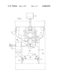
- FIG. 1 is a diagrammatic side elevation of a rotary printing press incorporating the invention.
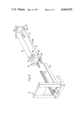
- FIG. 2 is a diagrammatic perspective view of an image cylinder mounting cradle and associated structure of the press.
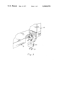
- FIG. 3 is a fragmentary exploded view partly sectioned showing an eccentric mounting for a cradle side roller.
- a rotary press for printing web material comprises a fixed frame 10, an impression cylinder carrier 11 extending transversely within the frame and which can be raised and lowered by fluid pressure rams 12, and an image cylinder cradle 13 which locates operatively within the lower part of the frame.
- Cradle 13 is shown in detail in FIG. 2 in a position withdrawn from frame 10.
- Said cradle comprises a transverse beam 14 to extend the full width of frame 10 and a pair of upstanding support members 15 in sliding engagement with longitudinal guide rails 16 on the top face of beam 14 so that their relative spacing and their position relative to the centre line of the press can be independently adjusted.
- Clamping means are provided, for example bolts engaging in T-slots (not shown) in beam 14, to secure members 15 at the desired position, beam 14 may conveniently bear graduation marks for their accurate positioning.
- Each support 15 defines an upwardly open semi-circular bearing formation 17 (FIG. 2) which operatively receives bearing journals 18 of stub shafts at opposite ends of an image cylinder 19 of the press.
- Journals 18 may consist of standard roller or ball race assemblies, the inner races being secured on the respective stub shafts and the outer races resting in the formations 17.
- cradle 13 In its operative position cradle 13 locates on slide means in the form of parallel transverse rails 21 of frame 10 and is adjustably positioned longitudinally by adjustable locating means in the form of a screw jack 22 (FIG. 2) which is releasably connected to one end of beam 14 by screw clamps 23a (one only shown) engaging in slots 23b on one end of beam 14. Lateral location of cradle 13 is provided by side rollers 24 on beam 14 which engage flanges of rails 21. Said rollers may be mounted on eccentric shafts.
- FIG. 3 shows, by way of example, a mode of mounting rollers 24.
- Each side roller 24 is freely rotatable on a stub shaft 30 on which it is retained by a spring clip 31, the shaft being releasably fixed to an undersurface of cradle 13 as by an integral flange 32 having a central locating spigot 33.
- Flange 32 is clamped as by screws 34 engaged in segmental slots permitting limited angular movement about the axis of spigot 33.
- the axis of shaft 30 is offset so as to be eccentric to spigot 33 enabling adjustment of the later positioning of cradle 13 between rails 21 to be made by altering the operative position of the rollers 24 by slackening screws 34 and rotating the mounting to the desired degree as by means of a squared outer end 35 on shaft 30.
- Carriage 14 has further rollers 25 on its underface to facilitate movement along rails 21 when released from jack 22.
- Impression cylinder carrier 11 mounts a single back-up roll 26 journalled directly above and in peripheral contact with impression cylinder 20 so that the axes of roll 26, and both cylinders 20 and 19 lie in a common vertical plane, impression cylinder 20 being operatively urged downwardly to form a nip with image cylinder 19 by the operation of rams 12, a web 27 being fed through said nip in conventional manner for printing, image cylinder 19 being fed with ink from a conventional inking system and doctored by a mechanism 28 which may be mounted on the frame 10 of the press, or possibly carried on the cradle 12.
Landscapes
- Engineering & Computer Science (AREA)
- Mechanical Engineering (AREA)
- Rotary Presses (AREA)
Abstract
Rotary printing press is provided with mounting means for an image cylinder to facilitate interchange of cylinders of different sizes and their adjustment. The cylinder is carried on upstanding supports on a cradle, end stub shafts of the cylinder being journalled on said supports and one or both of the latter being adjustable longitudinally of the cradle to suit cylinders of various axial lengths. The cradle is movable in a frame of the press either horizontally so that it can be withdrawn as a unit with the cylinder, or vertically for forming a nip with an impression cylinder.
Description
This is a continuation of application Ser. No. 462,766, filed Apr. 22, 1974, now abandoned.
This invention relates to rotary printing presses with particular, but not exclusive, reference to direct (i.e. non-offset) printing onto continuous web material.
The object of the invention is to provide improved mounting means for a printing (image bearing) cylinder of a rotary press (hereinafter referred to as the image cylinder) which facilitates interchange of cylinders, even if the cylinders are of different axial length, e.g. to accommodate webs or other materials of different widths; yet which provide accurate and secure operative positioning of said cylinders.
According to the invention there is provided a rotary printing press of the kind in which an image cylinder is operatively positioned directly below an impression cylinder to form a nip through which the material to be printed is operatively fed, characterised by a mounting cradle comprising a transverse beam, and a pair of upstanding supports located on the beam, at least one of which is selectively movable longitudinally thereof for adjustment of their relative spacing, each support having a bearing formation for receiving a respective journal of the image cylinder and said cradle being selectively movable in a frame of the press for positioning the image cylinder so journalled in operative relation to the impression cylinder.
Preferred embodiments of the invention are now more particularly described with reference to the accompanying drawings wherein:
FIG. 1 is a diagrammatic side elevation of a rotary printing press incorporating the invention.
FIG. 2 is a diagrammatic perspective view of an image cylinder mounting cradle and associated structure of the press; and
FIG. 3 is a fragmentary exploded view partly sectioned showing an eccentric mounting for a cradle side roller.
Referring to FIG. 1, a rotary press for printing web material comprises a fixed frame 10, an impression cylinder carrier 11 extending transversely within the frame and which can be raised and lowered by fluid pressure rams 12, and an image cylinder cradle 13 which locates operatively within the lower part of the frame.
Cradle 13 is shown in detail in FIG. 2 in a position withdrawn from frame 10. Said cradle comprises a transverse beam 14 to extend the full width of frame 10 and a pair of upstanding support members 15 in sliding engagement with longitudinal guide rails 16 on the top face of beam 14 so that their relative spacing and their position relative to the centre line of the press can be independently adjusted. Clamping means are provided, for example bolts engaging in T-slots (not shown) in beam 14, to secure members 15 at the desired position, beam 14 may conveniently bear graduation marks for their accurate positioning.
Each support 15 defines an upwardly open semi-circular bearing formation 17 (FIG. 2) which operatively receives bearing journals 18 of stub shafts at opposite ends of an image cylinder 19 of the press. Journals 18 may consist of standard roller or ball race assemblies, the inner races being secured on the respective stub shafts and the outer races resting in the formations 17.
In this way a range of image cylinders having different axial lengths can be readily accommodated, e.g. for printing various widths of web, appropriate adjustment of members 15 ensuring that cylinder 19 is accurately located in operating relationship to an impression cylinder 20 located by carrier 11. In an alternative construction one only of the members 15 is longitudinally adjustable on beam 14, the other support member being fixed. In this case the shorter length cylinders will be accommodated off-centre of the press.
In its operative position cradle 13 locates on slide means in the form of parallel transverse rails 21 of frame 10 and is adjustably positioned longitudinally by adjustable locating means in the form of a screw jack 22 (FIG. 2) which is releasably connected to one end of beam 14 by screw clamps 23a (one only shown) engaging in slots 23b on one end of beam 14. Lateral location of cradle 13 is provided by side rollers 24 on beam 14 which engage flanges of rails 21. Said rollers may be mounted on eccentric shafts. FIG. 3 shows, by way of example, a mode of mounting rollers 24. Each side roller 24 is freely rotatable on a stub shaft 30 on which it is retained by a spring clip 31, the shaft being releasably fixed to an undersurface of cradle 13 as by an integral flange 32 having a central locating spigot 33. Flange 32 is clamped as by screws 34 engaged in segmental slots permitting limited angular movement about the axis of spigot 33. The axis of shaft 30 is offset so as to be eccentric to spigot 33 enabling adjustment of the later positioning of cradle 13 between rails 21 to be made by altering the operative position of the rollers 24 by slackening screws 34 and rotating the mounting to the desired degree as by means of a squared outer end 35 on shaft 30. Carriage 14 has further rollers 25 on its underface to facilitate movement along rails 21 when released from jack 22.
Impression cylinder carrier 11 mounts a single back-up roll 26 journalled directly above and in peripheral contact with impression cylinder 20 so that the axes of roll 26, and both cylinders 20 and 19 lie in a common vertical plane, impression cylinder 20 being operatively urged downwardly to form a nip with image cylinder 19 by the operation of rams 12, a web 27 being fed through said nip in conventional manner for printing, image cylinder 19 being fed with ink from a conventional inking system and doctored by a mechanism 28 which may be mounted on the frame 10 of the press, or possibly carried on the cradle 12.
When it is desired to service or replace image cylinder 19 the nip pressure is removed by raising carrier 11, and cradle 13 is freed by releasing clamps 23a. The entire cradle 13 with cylinder 19 carried thereon can then be withdrawn from frame 10 by movement along rails 21 to the position shown in FIG. 2 where it may be received onto a trolley for facilitating subsequent handling.
Claims (2)
1. A rotary printing press having a frame and an image cylinder positioned on said frame in an operative position aligned directly below an impression cylinder, said impression cylinder being so mounted on the frame as to be selectively movable between a non-functioning position spaced above said image cylinder and an operative position where it cooperates with the operatively positioned image cylinder for forming a nip through which material to be printed may be fed, said press including a mounting cradle for said image cylinder comprising an elongate horizontal beam and a pair of upstanding supports on the beam, at least one of said supports being movable longitudinally of said beam for adjustment of the relative spacing of said supports and each support having bearing means rotatably mounting a respective end of the image cylinder; opposed horizontal slide means on said frame and extending transversely thereof on which said cradle is supported and along which said cradle is selectively movable in a direction parallel to the axis of rotation of the image cylinder for insertion into said frame for operatively positioning the image cylinder mounted thereon and for removal from said frame; locator means on opposite sides of the cradle adapted for engagement with and movement along substantially vertical longitudinal formations of the slide means to positively locate the cradle laterally of the slide means; and clamping means for releasable endwise connection of the cradle to the frame to positively maintain the cradle longitudinally of the slide means in the operative position of said image cylinder, said slide means comprising horizontally spaced rails along which the cradle is movable, said substantially vertical longitudinal formations being upright flanges on said rails, said locator means comprising rotatable side rollers on the cradle peripherally engaging said flanges, and at least some of said side rollers being eccentrically mounted for selectively adjustable positive location of the cradle laterally of the rails.
2. A printing press according to claim 1, wherein said rails are each provided with horizontal surfaces, and said cradle is supported on the rails by rollers rotatable about horizontal axes and peripherally engaging said horizontal surfaces.
Priority Applications (1)
| Application Number | Priority Date | Filing Date | Title |
|---|---|---|---|
| US05/613,751 US4046070A (en) | 1974-04-22 | 1975-09-16 | Rotary printing presses |
Applications Claiming Priority (2)
| Application Number | Priority Date | Filing Date | Title |
|---|---|---|---|
| US46276674A | 1974-04-22 | 1974-04-22 | |
| US05/613,751 US4046070A (en) | 1974-04-22 | 1975-09-16 | Rotary printing presses |
Related Parent Applications (1)
| Application Number | Title | Priority Date | Filing Date |
|---|---|---|---|
| US46276674A Continuation | 1974-04-22 | 1974-04-22 |
Publications (1)
| Publication Number | Publication Date |
|---|---|
| US4046070A true US4046070A (en) | 1977-09-06 |
Family
ID=27040446
Family Applications (1)
| Application Number | Title | Priority Date | Filing Date |
|---|---|---|---|
| US05/613,751 Expired - Lifetime US4046070A (en) | 1974-04-22 | 1975-09-16 | Rotary printing presses |
Country Status (1)
| Country | Link |
|---|---|
| US (1) | US4046070A (en) |
Cited By (27)
| Publication number | Priority date | Publication date | Assignee | Title |
|---|---|---|---|---|
| US4141293A (en) * | 1976-05-07 | 1979-02-27 | Machines Chambon | Rotary multi-color printing machine |
| US4239001A (en) * | 1977-09-14 | 1980-12-16 | Hiroshi Kataoka | Multicolor rotogravure printing system |
| US4344362A (en) * | 1980-01-08 | 1982-08-17 | Ryobi Ltd. | Impression cylinder cleaning device for printing machine |
| US4381707A (en) * | 1980-12-12 | 1983-05-03 | Windmoller & Holscher | Mechanism for lifting and lowering an impression cylinder with spring-biased multiple disc brake locking device |
| US4462311A (en) * | 1982-05-25 | 1984-07-31 | Machines Chambon | Offset printing machine with variable format |
| US4502384A (en) * | 1982-05-06 | 1985-03-05 | Bobst Sa | Method and device for changing printing elements in a printing unit of a press |
| US4616564A (en) * | 1978-12-14 | 1986-10-14 | Didde-Glaser, Inc. | Modular offset lithographic printing tower |
| US4622895A (en) * | 1984-09-21 | 1986-11-18 | Basf Aktiengesellschaft | Swivel frame apparatus for lining a wrap-around plate about a form cylinder |
| US4901641A (en) * | 1988-11-30 | 1990-02-20 | Bobst Sa | Printing press |
| US4989514A (en) * | 1988-11-25 | 1991-02-05 | Schiavi Cesare Costruzioni Meccaniche S.P.A. | Trolley carrying plural sets of print cylinder assemblies with independent drives |
| US5074207A (en) * | 1989-06-06 | 1991-12-24 | Windmoller & Holscher | Apparatus for moving a push-in truck carrying a printing cylinder into a printing press |
| US5132713A (en) * | 1991-03-15 | 1992-07-21 | Moore Business Forms, Inc. | Ion deposition web-fed print engine |
| US5186103A (en) * | 1992-06-12 | 1993-02-16 | Man Roland Druckmaschinen Ag | Printing machine system, especially for printing on a web of heavy or thick stock material, with interchangeable printing cylinders |
| EP0553779A1 (en) * | 1992-01-31 | 1993-08-04 | OFFICINE MECCANICHE GIOVANNI CERUTTI S.p.A. | Method for moving a printing carriage into and out of a printing unit and corresponding printing unit |
| US5275105A (en) * | 1991-04-09 | 1994-01-04 | Bobst Sa | Rotary printing machine equipped with an exchangeable cylinder |
| US5392710A (en) * | 1993-06-15 | 1995-02-28 | Li; Raymond | Modular feeder printing system |
| US5528987A (en) * | 1994-02-09 | 1996-06-25 | Tetra Laval Holdings & Finance S.A. | Rotary printing press unit suspended from beam frame |
| WO1997035721A1 (en) * | 1996-03-23 | 1997-10-02 | De La Rue Giori S.A. | Sheet processing machine |
| WO1999002345A1 (en) * | 1997-07-09 | 1999-01-21 | The Langston Corporation | Apparatus for printing corrugated board |
| EP0638419B1 (en) * | 1993-08-13 | 1999-05-06 | Maschinenfabrik Wifag | Supporting framework for a rotary web printing press |
| US6155166A (en) * | 1998-02-05 | 2000-12-05 | Uteco S.P.A. Roto-Flexo & Converting Machinery | Rotogravure printing and coating machine |
| US6668718B2 (en) * | 1997-03-13 | 2003-12-30 | Multi Print Systems B.V. | Printing machine with exchangeable ink application means |
| US6675707B1 (en) * | 1998-10-28 | 2004-01-13 | Heidelberger Druckmaschinen Ag | Positioning device in a printing machine |
| US20050139111A1 (en) * | 2002-04-09 | 2005-06-30 | Dieter Saupe | Device for positioning further processing devices on printing machines |
| JP2009143098A (en) * | 2007-12-13 | 2009-07-02 | Toyota Motor Corp | Gravure coater |
| US20120067231A1 (en) * | 2010-09-07 | 2012-03-22 | Michael Alan Vandenberg | Loading and/or unloading die cutting cylinders |
| US20150151532A1 (en) * | 2012-03-09 | 2015-06-04 | Kba-Notasys Sa | Ink wiping system of an intaglio printing press and intaglio printing press comprising the same |
Citations (5)
| Publication number | Priority date | Publication date | Assignee | Title |
|---|---|---|---|---|
| US2506011A (en) * | 1946-10-23 | 1950-05-02 | Champlain Company Inc | Enclosed fountain gravure press |
| US3384012A (en) * | 1965-10-13 | 1968-05-21 | Zerand Corp | Detachable printing cart for rotary printing presses |
| US3500744A (en) * | 1967-08-17 | 1970-03-17 | Modern Engraving & Machine Cor | In-line carriage arrangement for embossing machines |
| US3625145A (en) * | 1969-06-05 | 1971-12-07 | Bobst Champlain Inc | Cylinder cart for exchanging cylinders on the fly |
| US3783782A (en) * | 1972-08-04 | 1974-01-08 | Faustel Inc | Revolving turret for supporting printing press cart |
-
1975
- 1975-09-16 US US05/613,751 patent/US4046070A/en not_active Expired - Lifetime
Patent Citations (5)
| Publication number | Priority date | Publication date | Assignee | Title |
|---|---|---|---|---|
| US2506011A (en) * | 1946-10-23 | 1950-05-02 | Champlain Company Inc | Enclosed fountain gravure press |
| US3384012A (en) * | 1965-10-13 | 1968-05-21 | Zerand Corp | Detachable printing cart for rotary printing presses |
| US3500744A (en) * | 1967-08-17 | 1970-03-17 | Modern Engraving & Machine Cor | In-line carriage arrangement for embossing machines |
| US3625145A (en) * | 1969-06-05 | 1971-12-07 | Bobst Champlain Inc | Cylinder cart for exchanging cylinders on the fly |
| US3783782A (en) * | 1972-08-04 | 1974-01-08 | Faustel Inc | Revolving turret for supporting printing press cart |
Cited By (33)
| Publication number | Priority date | Publication date | Assignee | Title |
|---|---|---|---|---|
| US4141293A (en) * | 1976-05-07 | 1979-02-27 | Machines Chambon | Rotary multi-color printing machine |
| US4239001A (en) * | 1977-09-14 | 1980-12-16 | Hiroshi Kataoka | Multicolor rotogravure printing system |
| US4616564A (en) * | 1978-12-14 | 1986-10-14 | Didde-Glaser, Inc. | Modular offset lithographic printing tower |
| US4344362A (en) * | 1980-01-08 | 1982-08-17 | Ryobi Ltd. | Impression cylinder cleaning device for printing machine |
| US4381707A (en) * | 1980-12-12 | 1983-05-03 | Windmoller & Holscher | Mechanism for lifting and lowering an impression cylinder with spring-biased multiple disc brake locking device |
| US4502384A (en) * | 1982-05-06 | 1985-03-05 | Bobst Sa | Method and device for changing printing elements in a printing unit of a press |
| US4462311A (en) * | 1982-05-25 | 1984-07-31 | Machines Chambon | Offset printing machine with variable format |
| US4622895A (en) * | 1984-09-21 | 1986-11-18 | Basf Aktiengesellschaft | Swivel frame apparatus for lining a wrap-around plate about a form cylinder |
| US4989514A (en) * | 1988-11-25 | 1991-02-05 | Schiavi Cesare Costruzioni Meccaniche S.P.A. | Trolley carrying plural sets of print cylinder assemblies with independent drives |
| US4901641A (en) * | 1988-11-30 | 1990-02-20 | Bobst Sa | Printing press |
| US5074207A (en) * | 1989-06-06 | 1991-12-24 | Windmoller & Holscher | Apparatus for moving a push-in truck carrying a printing cylinder into a printing press |
| US5132713A (en) * | 1991-03-15 | 1992-07-21 | Moore Business Forms, Inc. | Ion deposition web-fed print engine |
| US5275105A (en) * | 1991-04-09 | 1994-01-04 | Bobst Sa | Rotary printing machine equipped with an exchangeable cylinder |
| EP0553779A1 (en) * | 1992-01-31 | 1993-08-04 | OFFICINE MECCANICHE GIOVANNI CERUTTI S.p.A. | Method for moving a printing carriage into and out of a printing unit and corresponding printing unit |
| US5186103A (en) * | 1992-06-12 | 1993-02-16 | Man Roland Druckmaschinen Ag | Printing machine system, especially for printing on a web of heavy or thick stock material, with interchangeable printing cylinders |
| US5392710A (en) * | 1993-06-15 | 1995-02-28 | Li; Raymond | Modular feeder printing system |
| EP0638419B1 (en) * | 1993-08-13 | 1999-05-06 | Maschinenfabrik Wifag | Supporting framework for a rotary web printing press |
| DE4327278C5 (en) * | 1993-08-13 | 2005-09-22 | Maschinenfabrik Wifag | Supporting frame for a web-fed rotary printing machine |
| US5528987A (en) * | 1994-02-09 | 1996-06-25 | Tetra Laval Holdings & Finance S.A. | Rotary printing press unit suspended from beam frame |
| WO1997035721A1 (en) * | 1996-03-23 | 1997-10-02 | De La Rue Giori S.A. | Sheet processing machine |
| US6112651A (en) * | 1996-03-23 | 2000-09-05 | De La Rue Giori S.A. | Foil-stamping machine that can accept stamping cylinders of different diameters |
| US6668718B2 (en) * | 1997-03-13 | 2003-12-30 | Multi Print Systems B.V. | Printing machine with exchangeable ink application means |
| US6412409B2 (en) | 1997-07-09 | 2002-07-02 | Joseph J. Weishew | Apparatus and method for printing corrugated board |
| WO1999002345A1 (en) * | 1997-07-09 | 1999-01-21 | The Langston Corporation | Apparatus for printing corrugated board |
| US6155166A (en) * | 1998-02-05 | 2000-12-05 | Uteco S.P.A. Roto-Flexo & Converting Machinery | Rotogravure printing and coating machine |
| US6675707B1 (en) * | 1998-10-28 | 2004-01-13 | Heidelberger Druckmaschinen Ag | Positioning device in a printing machine |
| US20050139111A1 (en) * | 2002-04-09 | 2005-06-30 | Dieter Saupe | Device for positioning further processing devices on printing machines |
| US7243602B2 (en) * | 2002-04-09 | 2007-07-17 | Man Roland Druckmaschinen Ag | Device for positioning further processing devices on printing machines |
| CN100335269C (en) * | 2002-04-09 | 2007-09-05 | 曼·罗兰·德鲁克马辛伦公司 | Device for positioning further processing devices on printing machines |
| JP2009143098A (en) * | 2007-12-13 | 2009-07-02 | Toyota Motor Corp | Gravure coater |
| US20120067231A1 (en) * | 2010-09-07 | 2012-03-22 | Michael Alan Vandenberg | Loading and/or unloading die cutting cylinders |
| US20150151532A1 (en) * | 2012-03-09 | 2015-06-04 | Kba-Notasys Sa | Ink wiping system of an intaglio printing press and intaglio printing press comprising the same |
| US9475273B2 (en) * | 2012-03-09 | 2016-10-25 | KBA—NotaSys SA | Ink wiping system of an intaglio printing press and intaglio printing press comprising the same |
Similar Documents
| Publication | Publication Date | Title |
|---|---|---|
| US4046070A (en) | Rotary printing presses | |
| JP3236305B2 (en) | Body support device for rotary printing press | |
| EP0105476B1 (en) | Rotary printing press | |
| SE8701105L (en) | DEVICE FOR LOADING AND UNLOADING PAPER ROLLS AT A ROLLING STAND TO A ROLLER PRINTING MACHINE | |
| US4552295A (en) | Anti-wrinkle device | |
| US5301609A (en) | Printing unit with skew and throw-off mechanisms | |
| US2751843A (en) | Self-adjusting form roll | |
| US3611924A (en) | Rotary offset printing press with cylinder interrupter | |
| MA33941B1 (en) | The hollow embossing printing machine with mobile cart supports the ink compound roll | |
| EP1101611A1 (en) | Device for exchangeably supporting and positioning printing cylinders of an offset printing press | |
| US6283024B1 (en) | Quick change print station for central impression presses | |
| US3986454A (en) | Multi-purpose side frames for rotary printing press | |
| GB2093438A (en) | Impression cylinders for sheet-fed rotogravure presses | |
| US3960076A (en) | Rotary screen printing machine with angle and pressure adjustable squeegee | |
| US5746132A (en) | Variable repeat plate and blanket cylinder mechanism | |
| JP2574330Y2 (en) | Wetting device for offset printing press | |
| US5320038A (en) | Method and apparatus for adjusting printing unit cylinders | |
| JPH07100559B2 (en) | Device for position adjustment of intermittently conveyed web | |
| US3563173A (en) | Liquid-handling mechanism | |
| JPH0336607B2 (en) | ||
| US3561359A (en) | Roller adjusting apparatus for a proof press | |
| US6712001B2 (en) | Arrangement for adjusting the interval between the rotational axes of cylinders | |
| KR910018179A (en) | Engraving drum cooling device for reclamatory printing paper feed | |
| US2674941A (en) | Rotary marking device | |
| CA1303900C (en) | Flexographic printing machine, especially for flexographic web printing |