US4022382A - Surface cleaning device - Google Patents
Surface cleaning device Download PDFInfo
- Publication number
- US4022382A US4022382A US05/679,051 US67905176A US4022382A US 4022382 A US4022382 A US 4022382A US 67905176 A US67905176 A US 67905176A US 4022382 A US4022382 A US 4022382A
- Authority
- US
- United States
- Prior art keywords
- tube
- fitting
- fittings
- tube segment
- cleaning device
- Prior art date
- Legal status (The legal status is an assumption and is not a legal conclusion. Google has not performed a legal analysis and makes no representation as to the accuracy of the status listed.)
- Expired - Lifetime
Links
Images
Classifications
-
- B—PERFORMING OPERATIONS; TRANSPORTING
- B05—SPRAYING OR ATOMISING IN GENERAL; APPLYING FLUENT MATERIALS TO SURFACES, IN GENERAL
- B05B—SPRAYING APPARATUS; ATOMISING APPARATUS; NOZZLES
- B05B3/00—Spraying or sprinkling apparatus with moving outlet elements or moving deflecting elements
- B05B3/18—Spraying or sprinkling apparatus with moving outlet elements or moving deflecting elements with elements moving in a straight line, e.g. along a track; Mobile sprinklers
-
- B—PERFORMING OPERATIONS; TRANSPORTING
- B05—SPRAYING OR ATOMISING IN GENERAL; APPLYING FLUENT MATERIALS TO SURFACES, IN GENERAL
- B05B—SPRAYING APPARATUS; ATOMISING APPARATUS; NOZZLES
- B05B1/00—Nozzles, spray heads or other outlets, with or without auxiliary devices such as valves, heating means
- B05B1/14—Nozzles, spray heads or other outlets, with or without auxiliary devices such as valves, heating means with multiple outlet openings; with strainers in or outside the outlet opening
- B05B1/20—Arrangements of several outlets along elongated bodies, e.g. perforated pipes or troughs, e.g. spray booms; Outlet elements therefor
- B05B1/202—Arrangements of several outlets along elongated bodies, e.g. perforated pipes or troughs, e.g. spray booms; Outlet elements therefor comprising inserted outlet elements
-
- B—PERFORMING OPERATIONS; TRANSPORTING
- B05—SPRAYING OR ATOMISING IN GENERAL; APPLYING FLUENT MATERIALS TO SURFACES, IN GENERAL
- B05B—SPRAYING APPARATUS; ATOMISING APPARATUS; NOZZLES
- B05B15/00—Details of spraying plant or spraying apparatus not otherwise provided for; Accessories
- B05B15/60—Arrangements for mounting, supporting or holding spraying apparatus
- B05B15/62—Arrangements for supporting spraying apparatus, e.g. suction cups
-
- B—PERFORMING OPERATIONS; TRANSPORTING
- B08—CLEANING
- B08B—CLEANING IN GENERAL; PREVENTION OF FOULING IN GENERAL
- B08B3/00—Cleaning by methods involving the use or presence of liquid or steam
- B08B3/02—Cleaning by the force of jets or sprays
- B08B3/024—Cleaning by means of spray elements moving over the surface to be cleaned
Definitions
- the present invention relates to a surface cleaning device and more specifically pertains to new and improved sweeping devices adapted to utilize water, wherein the water is sprayed therefrom in a plurality of jets against the surface to be swept or cleaned.
- Prior art devices of this type are generally made of steel tubing or pipe, are very rugged and heavy because they are intended for heavy duty applications and for the cleaning of large surface areas. These prior art sweeping devices, because of their construction, are cumbersome and difficult to maneuver and therefore are ineffective for the cleaning of smaller areas, such as decking around a swimming pool or the garage floor and driveway of a residence.
- An object of this invention is to provide a light-weight, easy to maneuver surface cleaning device for cleaning surfaces such as driveways and pool decking.
- Another object of this invention is to provide a surface cleaning device made of durable plastic or hard-rubber parts; said device being mounted on caster-type wheels at locations on said device that provide for maximum support and maneuverability.
- PVC-type tubing is used for a discharge tube having plastic nozzles therein to direct a wall of water, at relatively high pressure, at the surface to be cleaned.
- This discharge tube is coupled to a PVC-type inlet tube.
- the inlet tube is connected to a garden-type hose through any convenient coupler-valve arrangement.
- the discharge tube is mounted on a pair of caster-type wheels at locations on the tube that are approximately half-way between the junction of the discharge and inlet tubes and the respective ends of the discharge tube.
- the nozzles in the discharge tube are placed in the discharge tube at an angle that will divert the wall of water to the front of the surface cleaner when it is in an operating position.
- FIG. 1 is a perspective illustration of the cleaning device according to the present invention.
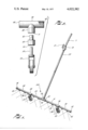
- FIG. 2 is an exploded elevation of the wheel mechanism of this invention and how it is fastened to the cleaning device.
- the surface cleaning apparatus as illustrated in FIG. 1 has an inlet tube 23 which is preferably made of polyvinylchloride at a 3/4 inch diameter.
- the inlet tube is connected to a discharge tube 24 which is really a plurality of tube segments 27, 29, 31 and 33. Each of these tube segments are the same type of polyvinylchloride tubing as the inlet tube 23.
- the inlet tube 23 is fastened to a coupling mechanism 19 which permits the coupling of a water hose 17, which may be of the ordinary garden variety type, thereto.
- the coupling mechanism 19 may also advantageously include a valve mechanism 21 for regulating the flow of water from the hose 17 into the inlet tube 23.
- the length of tubing 23 may be any convenient size, advantageous to facilitate manueverability of the device and avoid the requirement that the operator stoop during its operation. It has been found that a length of approximately 4 feet for inlet tubing 23 is very satisfactory.
- the discharge tube 24 is fastened to the inlet tube 23 by a T fitting 25 which may be a standard 3/4 inch PVC T coupling.
- the T fitting 25 couples inlet tube 23 to tube segments 27 and 31 of the discharge tube 24.
- Tube segments 29 and 33 are respectively coupled to tube segments 27 and 31 by T fittings 39.
- T fittings 39 may, like T fitting 25, be standard 3/4 inch PVC T couplings.
- the ends of tube segments 29 and 33 of the discharge tube 24 are capped by suitable plastic capping means 35, which are preferably cemented into position by conventional PVC cement.
- Each of the tube segments 27, 29, 31 and 33 of the discharge tube 24 have nozzles 45 inserted therein. These nozzles are made of plastic material press-fitted and glued into apertures in the tube segments 27, 29, 31 and 33.
- the T fittings 39 have their legs 38 aligned in parallel. These parallel legs 38 make an acute angle with the leg 26 of T fitting 25. It has been found that the most advantageous acute angle between the parallel legs 38 of T fittings 39 and the leg 26 of T fitting 25 is between 45° and 60° .
- the plastic nozzles 45 that are inserted into and are a part of the tube segments 27, 29, 31 and 33 of the discharge tube 24, are pointed in a direction toward the front of the cleaning device when in an operating position as shown in FIG. 1.
- the tube segments 27, 29, 31 and 33 are positioned within the T fittings 39 and 25, so that the nozzles 45 make an acute angle in a forward direction with respect to the legs 38 of the T fittings 39. It has been found that the most advantageous angle is 45° .
- the segments 27, 29, 31 and 33 of the discharge tube 24 advantageously are about 8 inches in length.
- a caster type wheel 47 is inserted into each of the T fittings 39, said caster being of the conventional universal-swivel type.
- FIG. 2 illustrates how the casters 47 are fastened to the discharge tube 24 in a removable manner.
- Each T fitting 39 has a leg 38 with an aperture 51 therein.
- the horizontal portion of the T fitting 39 may have threads 49 at either end thereof, or may simply have apertures therein as does the leg 38.
- a plug 53 is fashioned to fit snugly within the aperture 51 of the leg 38. The plug is held in place by conventional PVC cement.
- the stub portion 52 of the plug 53 that is inserted into the leg 38 is preferably tapered, being narrower at the top than at the bottom to facilitate ease of insertion and provide a very snug fit between the member 52 and the aperture 51 in the leg 38 of the T fitting 39.
- the plug 53 has an aperture therein that receives a sleeve 55 for the stud 57 of the caster wheel 47.
- the sleeve 55 is simply press fitted into this plug 53 much in the same way that it is press fitted into the wood leg of a chair or other similar piece of furniture.
Landscapes
- Vehicle Cleaning, Maintenance, Repair, Refitting, And Outriggers (AREA)
Abstract
A high pressure wall of water is directed at a surface to be cleaned from a plastic-type discharger tube having nozzles mounted therein. The discharge tube is joined at right angles to a plastic-type inlet tube. The inlet tube connects to a garden hose through a convenient valve and coupling arrangement. The discharge tube has caster-type wheels mounted thereto approximately midway between the union of the discharge tube and inlet tube and the respective ends of the discharge tube.
Description
The present invention relates to a surface cleaning device and more specifically pertains to new and improved sweeping devices adapted to utilize water, wherein the water is sprayed therefrom in a plurality of jets against the surface to be swept or cleaned.
Prior art devices of this type are generally made of steel tubing or pipe, are very rugged and heavy because they are intended for heavy duty applications and for the cleaning of large surface areas. These prior art sweeping devices, because of their construction, are cumbersome and difficult to maneuver and therefore are ineffective for the cleaning of smaller areas, such as decking around a swimming pool or the garage floor and driveway of a residence.
An object of this invention is to provide a light-weight, easy to maneuver surface cleaning device for cleaning surfaces such as driveways and pool decking.
Another object of this invention is to provide a surface cleaning device made of durable plastic or hard-rubber parts; said device being mounted on caster-type wheels at locations on said device that provide for maximum support and maneuverability.
These objects and the general purpose of the invention are accomplished as follows. PVC-type tubing is used for a discharge tube having plastic nozzles therein to direct a wall of water, at relatively high pressure, at the surface to be cleaned. This discharge tube is coupled to a PVC-type inlet tube. The inlet tube is connected to a garden-type hose through any convenient coupler-valve arrangement. The discharge tube is mounted on a pair of caster-type wheels at locations on the tube that are approximately half-way between the junction of the discharge and inlet tubes and the respective ends of the discharge tube. The nozzles in the discharge tube are placed in the discharge tube at an angle that will divert the wall of water to the front of the surface cleaner when it is in an operating position.
Other objects and many of the attendant advantages of this invention will be readily appreciated as the same becomes better understood by reference to the following detailed description when considered in conjunction with the accompanying drawings in which like reference numerals designate like parts throughout the figures thereof, and wherein:
FIG. 1 is a perspective illustration of the cleaning device according to the present invention.
FIG. 2 is an exploded elevation of the wheel mechanism of this invention and how it is fastened to the cleaning device.
The surface cleaning apparatus as illustrated in FIG. 1 has an inlet tube 23 which is preferably made of polyvinylchloride at a 3/4 inch diameter. The inlet tube is connected to a discharge tube 24 which is really a plurality of tube segments 27, 29, 31 and 33. Each of these tube segments are the same type of polyvinylchloride tubing as the inlet tube 23. The inlet tube 23 is fastened to a coupling mechanism 19 which permits the coupling of a water hose 17, which may be of the ordinary garden variety type, thereto. The coupling mechanism 19 may also advantageously include a valve mechanism 21 for regulating the flow of water from the hose 17 into the inlet tube 23. The length of tubing 23 may be any convenient size, advantageous to facilitate manueverability of the device and avoid the requirement that the operator stoop during its operation. It has been found that a length of approximately 4 feet for inlet tubing 23 is very satisfactory.
The discharge tube 24 is fastened to the inlet tube 23 by a T fitting 25 which may be a standard 3/4 inch PVC T coupling. The T fitting 25 couples inlet tube 23 to tube segments 27 and 31 of the discharge tube 24. Tube segments 29 and 33 are respectively coupled to tube segments 27 and 31 by T fittings 39. T fittings 39 may, like T fitting 25, be standard 3/4 inch PVC T couplings. The ends of tube segments 29 and 33 of the discharge tube 24 are capped by suitable plastic capping means 35, which are preferably cemented into position by conventional PVC cement.
Each of the tube segments 27, 29, 31 and 33 of the discharge tube 24 have nozzles 45 inserted therein. These nozzles are made of plastic material press-fitted and glued into apertures in the tube segments 27, 29, 31 and 33. The T fittings 39 have their legs 38 aligned in parallel. These parallel legs 38 make an acute angle with the leg 26 of T fitting 25. It has been found that the most advantageous acute angle between the parallel legs 38 of T fittings 39 and the leg 26 of T fitting 25 is between 45° and 60° .
The plastic nozzles 45 that are inserted into and are a part of the tube segments 27, 29, 31 and 33 of the discharge tube 24, are pointed in a direction toward the front of the cleaning device when in an operating position as shown in FIG. 1. The tube segments 27, 29, 31 and 33 are positioned within the T fittings 39 and 25, so that the nozzles 45 make an acute angle in a forward direction with respect to the legs 38 of the T fittings 39. It has been found that the most advantageous angle is 45° .
The segments 27, 29, 31 and 33 of the discharge tube 24 advantageously are about 8 inches in length. A caster type wheel 47 is inserted into each of the T fittings 39, said caster being of the conventional universal-swivel type.
FIG. 2 illustrates how the casters 47 are fastened to the discharge tube 24 in a removable manner. Each T fitting 39 has a leg 38 with an aperture 51 therein. The horizontal portion of the T fitting 39 may have threads 49 at either end thereof, or may simply have apertures therein as does the leg 38. A plug 53 is fashioned to fit snugly within the aperture 51 of the leg 38. The plug is held in place by conventional PVC cement. The stub portion 52 of the plug 53 that is inserted into the leg 38 is preferably tapered, being narrower at the top than at the bottom to facilitate ease of insertion and provide a very snug fit between the member 52 and the aperture 51 in the leg 38 of the T fitting 39. The plug 53 has an aperture therein that receives a sleeve 55 for the stud 57 of the caster wheel 47. The sleeve 55 is simply press fitted into this plug 53 much in the same way that it is press fitted into the wood leg of a chair or other similar piece of furniture.
By providing placement of the caster wheels 47 equidistant between the junction T fitting 25 and the ends of the discharge tubing 24, and manufacturing the entire cleaning device from PVC-type plastic tubing material, a light-weight easy to maneuver surface cleaning device is provided.
Obviously, many modifications and variations of the present invention are possible in the light of the above teachings. It is therefore to be understood that within the scope of the appended claims the invention may be practiced otherwise than as specifically described.
Claims (9)
1. A surface cleaning device for cleaning substantially flat surfaces, comprising:
a discharge tube, said discharge tube including:
a first tube segment having at least one discharge nozzle therein, a cap closing a first end of said tube segment, the second end of said tube segment being fastened to a first T fitting;
a second tube segment having at least one discharge nozzle therein, a first end of said second tube segment being fastened to said first T fitting in line with said first tube segment, the second end of said tube segment being fastened to a second T fitting;
a third tube segment having at least one discharge nozzle therein, a first end of said first tube segment being fastened to said second T fitting, in line with said second tube segment, the second end of said third tube segment being fastened to a third T fitting;
a fourth tube segment having at least one discharge nozzle therein, a first end of said fourth tube segment being fastened to said third T fitting, in line with said third tube segment, a cap closing the second end of said fourth tube segment;
an inlet tube connected to said second T fitting, said inlet tube having a coupling means attached thereto for connection to a water hose; and
a pair of caster-type wheels, one connected to said first T fitting, the other connected to said third T fitting.
2. The surface cleaning device of claim 1 wherein said first, second, third and fourth tube segments are equal in length.
3. The surface cleaning device of claim 2, further comprising:
plug means for the upstanding leg of said first and third T fittings, each of said plug means sized to seal the opening in the leg of its respective T fitting and having an aperture therein to receive the stud sleeve of a caster type wheel.
4. The surface cleaning device of claim 3, wherein said first and third T fittings have their leg portions oriented at an acute angle with the leg portion of said second T fitting.
5. The surface cleaning device of claim 4 wherein said first, second, third and fourth tube segments are fastened to said first and third T fittings so as to orient the nozzles in the respective tube segments at an acute angle with the leg portion of said first and third T fittings, the leg portion of said first and third T fittings being parallel.
6. The surface cleaning device of claim 1, further comprising:
plug means for the upstanding leg of said first and third T fittings, each of said plug means sized to seal the opening in the leg of its respective T fitting and having an aperture therein to receive the stud sleeve of a caster type wheel.
7. The surface cleaning device of claim 1, wherein said first and third T fittings have their leg portions oriented at an acute angle with the leg portion of said second T fitting.
8. The surface cleaning device of claim 7, wherein said first, second, third and fourth tube segments are fastened to said first and third T fittings so as to orient the nozzles in the respective tube segments at an acute angle with the leg portion of said first and third T fittings, the leg portions of said first and third T fittings being parallel.
9. The surface cleaning device of claim 7, wherein the leg portions of said first and third T fittings are parallel.
Priority Applications (1)
| Application Number | Priority Date | Filing Date | Title |
|---|---|---|---|
| US05/679,051 US4022382A (en) | 1976-04-21 | 1976-04-21 | Surface cleaning device |
Applications Claiming Priority (1)
| Application Number | Priority Date | Filing Date | Title |
|---|---|---|---|
| US05/679,051 US4022382A (en) | 1976-04-21 | 1976-04-21 | Surface cleaning device |
Publications (1)
| Publication Number | Publication Date |
|---|---|
| US4022382A true US4022382A (en) | 1977-05-10 |
Family
ID=24725383
Family Applications (1)
| Application Number | Title | Priority Date | Filing Date |
|---|---|---|---|
| US05/679,051 Expired - Lifetime US4022382A (en) | 1976-04-21 | 1976-04-21 | Surface cleaning device |
Country Status (1)
| Country | Link |
|---|---|
| US (1) | US4022382A (en) |
Cited By (28)
| Publication number | Priority date | Publication date | Assignee | Title |
|---|---|---|---|---|
| US4095746A (en) * | 1977-01-31 | 1978-06-20 | Anderberg Thomas A | Self-supported water sweeper |
| US4221228A (en) * | 1978-09-15 | 1980-09-09 | Advanced Curing Systems, Inc. | Piece part washer |
| US4580726A (en) * | 1984-04-30 | 1986-04-08 | Unger Michel J | Under-car wash |
| US4930706A (en) * | 1988-10-03 | 1990-06-05 | Arthur Merlin | Water broom |
| US4966717A (en) * | 1989-02-10 | 1990-10-30 | Kern Donald W | Ozone injection system and method |
| US5381964A (en) * | 1993-02-12 | 1995-01-17 | Reyna; John M. | Water jet spray nozzle for cleaning a paintbrush |
| US5653392A (en) * | 1995-11-13 | 1997-08-05 | Wells; Joseph H. | Water spray apparatus |
| US5908163A (en) * | 1995-11-13 | 1999-06-01 | Wells; Joseph H. | Spray apparatus |
| WO2000003620A1 (en) | 1998-07-20 | 2000-01-27 | Delaine Phillip M Jr | Aqua broom |
| US6079640A (en) * | 1998-04-13 | 2000-06-27 | Merritts; Gary W. | Auto underwasher |
| US6105593A (en) * | 1998-05-22 | 2000-08-22 | Jet, Inc. | Fixed film media cleaner apparatus and method |
| WO2001005275A1 (en) | 1999-07-15 | 2001-01-25 | Delaine Phillip M Jr | Oscillating aquabroom |
| US6688540B1 (en) | 2002-09-23 | 2004-02-10 | Richard Nicholas Passarella | Power washer standoff |
| US20040177870A1 (en) * | 2003-03-10 | 2004-09-16 | Wilson Donald W. | Curb and sidewalk cleaner |
| WO2004091293A1 (en) * | 2003-04-16 | 2004-10-28 | The Crown In The Right Of The State Of Queensland Acting Through The Department Of Primary Industries & Fisheries (Forestry) | Hand operated agricultural chemical applicator |
| US6892552B2 (en) | 2003-01-06 | 2005-05-17 | Physics Support Services, Llc | System and method for cooling air inhaled by air conditioning housing unit |
| US6935579B1 (en) | 2004-01-07 | 2005-08-30 | Jimmie L. Lindsey | Dual spray cleaning apparatus |
| US20050194757A1 (en) * | 2004-03-04 | 2005-09-08 | Scott David K. | Vehicle |
| US7314186B1 (en) * | 2005-01-31 | 2008-01-01 | Aesch Jr Harold W | Wheel mounted spraying assembly and method |
| US7325756B1 (en) * | 2006-09-05 | 2008-02-05 | Giorgis Getachew W | Roll-sprinkler irrigation system |
| US20080028556A1 (en) * | 2006-06-22 | 2008-02-07 | Hans Papenfuss | Paint brush cleaning device |
| US20110047726A1 (en) * | 2009-09-02 | 2011-03-03 | John James | Manual swimming pool cleaning apparatus employing a plurality of water jets |
| US20110271981A1 (en) * | 2009-01-16 | 2011-11-10 | Patrick Jeremy Rice | Cleaner |
| US20120240638A1 (en) * | 2011-03-24 | 2012-09-27 | Stephen Edward Hettinger | Device and method for rinsing objects in an appliance |
| US9777444B1 (en) * | 2016-06-28 | 2017-10-03 | Michael S. Dellario | Self-lubricating asphalt rake |
| US20180030678A1 (en) * | 2016-08-01 | 2018-02-01 | Specialized Pavement Marking, Inc. | Striping apparatus |
| US20190210698A1 (en) * | 2018-01-11 | 2019-07-11 | Paul K. Sunden | Foot sprayer attached to watercraft |
| US20200230636A1 (en) * | 2019-01-18 | 2020-07-23 | Rooftop Research, Llc | Fluid Dispensing System |
Citations (4)
| Publication number | Priority date | Publication date | Assignee | Title |
|---|---|---|---|---|
| US2692163A (en) * | 1951-12-03 | 1954-10-19 | Frances E Shreve | Water sweeping device |
| US3202362A (en) * | 1963-10-16 | 1965-08-24 | George R Wright | Solution dispensing assembly |
| US3770210A (en) * | 1972-09-07 | 1973-11-06 | C Veltkamp | Water sweep |
| US3931931A (en) * | 1975-02-20 | 1976-01-13 | Otis George A | Surface washer |
-
1976
- 1976-04-21 US US05/679,051 patent/US4022382A/en not_active Expired - Lifetime
Patent Citations (4)
| Publication number | Priority date | Publication date | Assignee | Title |
|---|---|---|---|---|
| US2692163A (en) * | 1951-12-03 | 1954-10-19 | Frances E Shreve | Water sweeping device |
| US3202362A (en) * | 1963-10-16 | 1965-08-24 | George R Wright | Solution dispensing assembly |
| US3770210A (en) * | 1972-09-07 | 1973-11-06 | C Veltkamp | Water sweep |
| US3931931A (en) * | 1975-02-20 | 1976-01-13 | Otis George A | Surface washer |
Cited By (31)
| Publication number | Priority date | Publication date | Assignee | Title |
|---|---|---|---|---|
| US4095746A (en) * | 1977-01-31 | 1978-06-20 | Anderberg Thomas A | Self-supported water sweeper |
| US4221228A (en) * | 1978-09-15 | 1980-09-09 | Advanced Curing Systems, Inc. | Piece part washer |
| US4580726A (en) * | 1984-04-30 | 1986-04-08 | Unger Michel J | Under-car wash |
| US4930706A (en) * | 1988-10-03 | 1990-06-05 | Arthur Merlin | Water broom |
| US4966717A (en) * | 1989-02-10 | 1990-10-30 | Kern Donald W | Ozone injection system and method |
| US5381964A (en) * | 1993-02-12 | 1995-01-17 | Reyna; John M. | Water jet spray nozzle for cleaning a paintbrush |
| US5653392A (en) * | 1995-11-13 | 1997-08-05 | Wells; Joseph H. | Water spray apparatus |
| US5908163A (en) * | 1995-11-13 | 1999-06-01 | Wells; Joseph H. | Spray apparatus |
| US6079640A (en) * | 1998-04-13 | 2000-06-27 | Merritts; Gary W. | Auto underwasher |
| US6105593A (en) * | 1998-05-22 | 2000-08-22 | Jet, Inc. | Fixed film media cleaner apparatus and method |
| WO2000003620A1 (en) | 1998-07-20 | 2000-01-27 | Delaine Phillip M Jr | Aqua broom |
| WO2001005275A1 (en) | 1999-07-15 | 2001-01-25 | Delaine Phillip M Jr | Oscillating aquabroom |
| US6688540B1 (en) | 2002-09-23 | 2004-02-10 | Richard Nicholas Passarella | Power washer standoff |
| US6892552B2 (en) | 2003-01-06 | 2005-05-17 | Physics Support Services, Llc | System and method for cooling air inhaled by air conditioning housing unit |
| US20040177870A1 (en) * | 2003-03-10 | 2004-09-16 | Wilson Donald W. | Curb and sidewalk cleaner |
| WO2004091293A1 (en) * | 2003-04-16 | 2004-10-28 | The Crown In The Right Of The State Of Queensland Acting Through The Department Of Primary Industries & Fisheries (Forestry) | Hand operated agricultural chemical applicator |
| US6935579B1 (en) | 2004-01-07 | 2005-08-30 | Jimmie L. Lindsey | Dual spray cleaning apparatus |
| US20050194757A1 (en) * | 2004-03-04 | 2005-09-08 | Scott David K. | Vehicle |
| US7249778B2 (en) | 2004-03-04 | 2007-07-31 | Flexibility Concepts, Ltd. | Vehicle |
| US7314186B1 (en) * | 2005-01-31 | 2008-01-01 | Aesch Jr Harold W | Wheel mounted spraying assembly and method |
| US20080028556A1 (en) * | 2006-06-22 | 2008-02-07 | Hans Papenfuss | Paint brush cleaning device |
| US7325756B1 (en) * | 2006-09-05 | 2008-02-05 | Giorgis Getachew W | Roll-sprinkler irrigation system |
| US20180228278A1 (en) * | 2009-01-16 | 2018-08-16 | Patrick Jeremy Rice | Cleaner |
| US20110271981A1 (en) * | 2009-01-16 | 2011-11-10 | Patrick Jeremy Rice | Cleaner |
| US20110047726A1 (en) * | 2009-09-02 | 2011-03-03 | John James | Manual swimming pool cleaning apparatus employing a plurality of water jets |
| US9109321B2 (en) * | 2011-03-24 | 2015-08-18 | General Electric Company | Device and method for rinsing objects in an appliance |
| US20120240638A1 (en) * | 2011-03-24 | 2012-09-27 | Stephen Edward Hettinger | Device and method for rinsing objects in an appliance |
| US9777444B1 (en) * | 2016-06-28 | 2017-10-03 | Michael S. Dellario | Self-lubricating asphalt rake |
| US20180030678A1 (en) * | 2016-08-01 | 2018-02-01 | Specialized Pavement Marking, Inc. | Striping apparatus |
| US20190210698A1 (en) * | 2018-01-11 | 2019-07-11 | Paul K. Sunden | Foot sprayer attached to watercraft |
| US20200230636A1 (en) * | 2019-01-18 | 2020-07-23 | Rooftop Research, Llc | Fluid Dispensing System |
Similar Documents
| Publication | Publication Date | Title |
|---|---|---|
| US4022382A (en) | Surface cleaning device | |
| US5456412A (en) | High pressure surface washing device | |
| US5695121A (en) | Self contained portable sprayer system | |
| US6739787B1 (en) | Joint device | |
| US4333203A (en) | Conversion attachment for a wet-dry vacuum cleaner | |
| US3063077A (en) | Device for the cleaning of swimming pools and the like | |
| US5113547A (en) | Adjustable wand for carpet soil extractors | |
| US6568610B1 (en) | Flexible lawn and garden spray wand | |
| US4562963A (en) | Garden sprinkler | |
| US6341738B1 (en) | Power washer wand | |
| US4998317A (en) | Combined vacuum and fluid line hose | |
| US5653392A (en) | Water spray apparatus | |
| JPH09503398A (en) | Vacuum cleaner with improved steering characteristics | |
| US6413002B1 (en) | Aqua broom | |
| US3503554A (en) | Fountain display apparatus | |
| US5908163A (en) | Spray apparatus | |
| US4537522A (en) | Paint dispensing applicator with safety features | |
| US9586239B2 (en) | Three wheel, mobile frame | |
| US20100025497A1 (en) | Fluid flush device with optional telescopic wand | |
| US4011994A (en) | Transportable ground spraying device | |
| JPH11222276A (en) | Spray tank having internal thread and swivel hose joint | |
| US3547458A (en) | Steering attachment for swimming pool vacuum head | |
| US9533320B1 (en) | Portable vehicle undercarriage cleaner | |
| US5201953A (en) | Vehicular paint applicator for corrugated surfaces | |
| US3770210A (en) | Water sweep |