US3947646A - Resilient microphone mounting - Google Patents
Resilient microphone mounting Download PDFInfo
- Publication number
- US3947646A US3947646A US05/564,031 US56403175A US3947646A US 3947646 A US3947646 A US 3947646A US 56403175 A US56403175 A US 56403175A US 3947646 A US3947646 A US 3947646A
- Authority
- US
- United States
- Prior art keywords
- microphone
- cylinder
- holder according
- microphone holder
- attaching
- Prior art date
- Legal status (The legal status is an assumption and is not a legal conclusion. Google has not performed a legal analysis and makes no representation as to the accuracy of the status listed.)
- Expired - Lifetime
Links
- 230000010355 oscillation Effects 0.000 claims abstract description 20
- 239000012858 resilient material Substances 0.000 claims abstract description 4
- 230000003014 reinforcing effect Effects 0.000 claims description 9
- 230000015572 biosynthetic process Effects 0.000 claims 1
- 239000000725 suspension Substances 0.000 abstract description 2
- 230000000694 effects Effects 0.000 description 4
- 230000003139 buffering effect Effects 0.000 description 3
- 238000002955 isolation Methods 0.000 description 3
- 239000004033 plastic Substances 0.000 description 3
- 229920003023 plastic Polymers 0.000 description 3
- 230000005540 biological transmission Effects 0.000 description 2
- 229920001971 elastomer Polymers 0.000 description 2
- 238000010276 construction Methods 0.000 description 1
- 238000002788 crimping Methods 0.000 description 1
- 238000006073 displacement reaction Methods 0.000 description 1
- 239000004744 fabric Substances 0.000 description 1
- 239000000463 material Substances 0.000 description 1
- 239000007769 metal material Substances 0.000 description 1
- 239000004745 nonwoven fabric Substances 0.000 description 1
- 229920001084 poly(chloroprene) Polymers 0.000 description 1
Images


Classifications
-
- H—ELECTRICITY
- H04—ELECTRIC COMMUNICATION TECHNIQUE
- H04R—LOUDSPEAKERS, MICROPHONES, GRAMOPHONE PICK-UPS OR LIKE ACOUSTIC ELECTROMECHANICAL TRANSDUCERS; DEAF-AID SETS; PUBLIC ADDRESS SYSTEMS
- H04R1/00—Details of transducers, loudspeakers or microphones
- H04R1/08—Mouthpieces; Microphones; Attachments therefor
-
- H—ELECTRICITY
- H04—ELECTRIC COMMUNICATION TECHNIQUE
- H04R—LOUDSPEAKERS, MICROPHONES, GRAMOPHONE PICK-UPS OR LIKE ACOUSTIC ELECTROMECHANICAL TRANSDUCERS; DEAF-AID SETS; PUBLIC ADDRESS SYSTEMS
- H04R1/00—Details of transducers, loudspeakers or microphones
- H04R1/20—Arrangements for obtaining desired frequency or directional characteristics
- H04R1/22—Arrangements for obtaining desired frequency or directional characteristics for obtaining desired frequency characteristic only
- H04R1/222—Arrangements for obtaining desired frequency or directional characteristics for obtaining desired frequency characteristic only for microphones
Definitions
- the invention relates to a microphone holder, and more particularly to a microphone holder for use in an electrical instrument which internally houses a microphone.
- a microphone holder including a microphone supporting cylinder which is mechanically associated with an externally located attaching cylinder, both integrally formed of a resilient material such as rubber.
- the use of such a microphone holder maintains the microphone which is fitted inside the supporting cylinder in suspension within the attaching cylinder, and produces a substantially improved isolation against oscillations which may be transmitted through the body of the instruments by virtue of the resilience of the component parts of the holder as well as the effect of double structure comprising the supporting and attaching cylinders.
- the microphone holder thus constructed, the transmission of an amount of oscillations, though reduced, remains, and therefore, has a significant influence upon the performance, and particularly, the performance of a highly sensitive microphone.
- a stepped connecting cylinder which presents a high resistance to the transmission of oscillations, and hence the possibility of the microphone producing noises in response to transmitted oscillations can be substantially eliminated.
- the stepped connecting cylinder increases the length of a path from the microphone supporting cylinder to the anchorage of the attaching sleeve and thus provides an increased buffering path length. Also an additional air gap is created between the connecting cylinder and the microphone, which substantially improves the oscillation isolating effect.
- the oscillation isolating effect can be further increased by providing at least one reinforcing structure, which may comprise an oscillation absorbing structure and/or a reduced wall thickness structure at a suitable location of the microphone holder.
- FIG. 1 is a cross section of the microphone holder constructed in accordance with one embodiment of the invention and illustrating the manner of its attachment to an electrical instrument;
- FIG. 2 is a partially sectionalized perspective view of the microphone holder shown in FIG. 1;
- FIGS. 3 and 4 are cross sections of other embodiments of the invention.
- FIG. 5 is a side elevation of the microphone holder shown in FIG. 4, as viewed from the right-hand side of FIG. 4;
- FIG. 6 is a perspective view of a stepped connecting cylinder
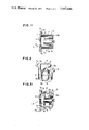
- FIG. 7 is a cross section of a microphone holder constructed in accordance with an additional embodiment of the invention.
- FIG. 8 is a side elevation of the microphone holder shown in FIG. 7, as viewed from the right-hand side thereof;
- FIGS. 9 to 11 are cross sections illustrating further embodiments of the microphone holder of the invention.
- FIG. 12 is a cross section of the microphone holder taken along the line A--A of FIG. 11.
- a body portion 1 of an electrical instrument such as a tape recorder which internally houses a microphone.
- the body portion is provided with a grid assembly 2 of a conventional design having a number of perforations 3 for collecting sound and transmitting it to a microphone 4 which is located inside thereof and carried by a microphone holder 5.
- the microphone holder 5 essentially comprises a microphone supporting cylinder 6, an attaching cylinder 7 which is located outside the supporting cylinder 6, and a stepped connecting cylinder 8 which connects the cylinders 6, 7 together, all of which are integrally moulded from a resilient material such as rubber, neoprene rubber, elastic plastics or the like.
- the microphone supporting cylinder 6 At its one end nearer the connecting cylinder 8, the microphone supporting cylinder 6 has an inner diameter which is equal to the outer diameter of the microphone 4 fitted therein, and the entire cylinder 6 is tapered forwardly or toward the grid assembly (see FIG. 2).
- the connecting cylinder 8 includes a step 8a lying in a single plane and connected with the end of the microphone supporting cylinder 6 which is remote from the grid assembly and a base 8b which is connected with the free end of the attaching cylinder 7.
- the attaching cylinder 7 is in a configuration folded back from the connecting cylinder 8 and is located externally of the microphone supporting cylinder 6.
- the attaching cylinder 7 is provided with a pair of diametrically opposite tabs 7a, 7b having apertures 7a1, 7b1 therein. These apertures are engaged by a pair of pegs or joggles 1a, 1b integral with the body portion 1, the top of the joggles being swaged to secure the microphone holder 5 inside the grid assembly 2.
- the joggles 1a, 1b can be heat swaged.
- the holder 5 can be secured to the body portion by any other conventional means such as adhesion, threaded connection or crimping.
- a screen 9 comprising a meshwork, a cloth, a porous non-woven fabric of foamed polyurethene or the like is applied on the inner surface of the grid assembly 2. The screen 9 may be interposed between the body portion 1 and the attaching sleeve 7 to further increase the oscillation isolating effect.
- FIGS. 3 to 12 illustrate other embodiments of the invention.
- the parts having the same function as those illustrated in FIGS. 1 and 2 are designated by like characters without repeating their description.
- the microphone holder 5 includes bellows 10 formed in the attaching cylinder 7 so as to serve as a buffering member.
- the microphone holder 5 includes a modified connecting cylinder 11 which is provided with a helical step 11a.
- the helical construction of the step 11a serves as a reinforcing structure, whereby the wall thickness of the connecting cylinder 11 can be reduced without impairing its strength to hold the microphone 4.
- this configuration facilitates the removal of a moulded product from a mould used and prevents damage to the product.
- the attaching cylinder 7 is provided with a surrounding square flange 7c having a pair of mounting holes 7a1, 7b1 at its diametrical corners.
- the connecting cylinder 8 is connected with the microphone supporting cylinder 6 at its one end 8a and is also connected with the attaching cylinder 7 at its other end or bottom 8b.
- Spaced recesses 8b1, 8b2 and 8b3 are formed in the bottom 8b to reduce its thickness, and the portions of the bottom which are located between these recesses have an increased thickness to serve as a reinforcing structure.
- the microphone 4 is formed with a step 4a at its left-hand end which is engaged by a stepped detent 6a formed at the forward end of the microphone supporting cylinder 6.
- the stepped detent 6a serves as a reinforcing structure and also as a stop when fitting the microphone 4 into the supporting cylinder 6.
- the detent 6a prevents a displacement of the microphone 4 as a result of oscillations which may be imparted thereto.
- a pair of oscillation absorbing interconnected cylinders 12a, 12b are arranged between and integrally connected with the attaching cylinder 7 and the connecting cylinder 8.
- Increasing the number of connecting cylinders in this manner achieves a very satisfactory isolation of oscillations in that they constitute together an oscillation absorbing structure by themselves and also increase the buffering path which the oscillations must travel before being transmitted to the microphone.
- FIGS. 11 and 12 there is shown an arrangement of the microphone holder 5 using a modified attaching cylinder 13.
- the attaching cylinder 13 is provided with four semicylindrical ribs 13a, 13b, 13c and 13d which are equiangularly spaced around the outer periphery and extend the length of the attaching cylinder 13.
- the remainder of the attaching cylinder 13 has a reduced wall thickness.
- the ribs 13a, 13b, 13c and 13d reinforce the overall structure, thereby permitting a reduction in the wall thickness of the cylinder.
- the attaching cylinder 13 is provided with a surrounding square flange 13e in which a pair of mounting holes 13e1, 13e2 are formed at diametrically opposite corners thereof.
- any of the reinforcing structures, the oscillation absorbing structures and/or the reduced thickness structure can be used either alone or in combination at a suitable location of the microphone holder 5.
- the configuration of the mounting tabs or flanges of the attaching cylinders and the number of mounting holes, the number and extent of undulations in the bellows, the number of turns in the helical step of the microphone supporting cylinder, the number as well as the width and depth of the recesses formed in the connecting cylinder, the number of connecting cylinders used, or the size and the number of cylindrical ribs on the attaching cylinder is a matter of design.
Landscapes
- Physics & Mathematics (AREA)
- Engineering & Computer Science (AREA)
- Acoustics & Sound (AREA)
- Signal Processing (AREA)
- Health & Medical Sciences (AREA)
- Otolaryngology (AREA)
- Details Of Audible-Bandwidth Transducers (AREA)
Abstract
A microphone holder essentially comprises a microphone supporting cylinder for mounting a microphone therein, an attaching cylinder located outside the supporting cylinder, and a stepped connecting cylinder for connecting the supporting and attaching cylinders together, all of which are integrally formed of a resilient material to support the microphone in suspension, thereby isolating it against oscillations which may be imparted thereto.
Description
The invention relates to a microphone holder, and more particularly to a microphone holder for use in an electrical instrument which internally houses a microphone.
In electrical instruments such as tape recorders which internally house a microphone, an inconvenience is experienced in that oscillations from an electric motor or other rotating members may be transmitted through the body of such instruments to the microphone to cause a noise therefrom.
To overcome such an inconvenience, there has been proposed a microphone holder including a microphone supporting cylinder which is mechanically associated with an externally located attaching cylinder, both integrally formed of a resilient material such as rubber. The use of such a microphone holder maintains the microphone which is fitted inside the supporting cylinder in suspension within the attaching cylinder, and produces a substantially improved isolation against oscillations which may be transmitted through the body of the instruments by virtue of the resilience of the component parts of the holder as well as the effect of double structure comprising the supporting and attaching cylinders. However, with the microphone holder thus constructed, the transmission of an amount of oscillations, though reduced, remains, and therefore, has a significant influence upon the performance, and particularly, the performance of a highly sensitive microphone.
It is an object of the invention to provide a microphone holder which includes a stepped connecting cylinder located intermediate and interconnecting the microphone supporting cylinder and the attaching cylinder to thereby produce complete isolation of the microphone against oscillations which may be transmitted thereto.
In accordance with the invention, there is provided a stepped connecting cylinder which presents a high resistance to the transmission of oscillations, and hence the possibility of the microphone producing noises in response to transmitted oscillations can be substantially eliminated. In the microphone holder of the invention, the stepped connecting cylinder increases the length of a path from the microphone supporting cylinder to the anchorage of the attaching sleeve and thus provides an increased buffering path length. Also an additional air gap is created between the connecting cylinder and the microphone, which substantially improves the oscillation isolating effect.
Moreover, the oscillation isolating effect can be further increased by providing at least one reinforcing structure, which may comprise an oscillation absorbing structure and/or a reduced wall thickness structure at a suitable location of the microphone holder.
FIG. 1 is a cross section of the microphone holder constructed in accordance with one embodiment of the invention and illustrating the manner of its attachment to an electrical instrument;
FIG. 2 is a partially sectionalized perspective view of the microphone holder shown in FIG. 1;
FIGS. 3 and 4 are cross sections of other embodiments of the invention;
FIG. 5 is a side elevation of the microphone holder shown in FIG. 4, as viewed from the right-hand side of FIG. 4;
FIG. 6 is a perspective view of a stepped connecting cylinder;
FIG. 7 is a cross section of a microphone holder constructed in accordance with an additional embodiment of the invention;
FIG. 8 is a side elevation of the microphone holder shown in FIG. 7, as viewed from the right-hand side thereof;
FIGS. 9 to 11 are cross sections illustrating further embodiments of the microphone holder of the invention; and
FIG. 12 is a cross section of the microphone holder taken along the line A--A of FIG. 11.
Referring to FIG. 1, there is shown a body portion 1 of an electrical instrument such as a tape recorder which internally houses a microphone. The body portion is provided with a grid assembly 2 of a conventional design having a number of perforations 3 for collecting sound and transmitting it to a microphone 4 which is located inside thereof and carried by a microphone holder 5.
The microphone holder 5 essentially comprises a microphone supporting cylinder 6, an attaching cylinder 7 which is located outside the supporting cylinder 6, and a stepped connecting cylinder 8 which connects the cylinders 6, 7 together, all of which are integrally moulded from a resilient material such as rubber, neoprene rubber, elastic plastics or the like.
At its one end nearer the connecting cylinder 8, the microphone supporting cylinder 6 has an inner diameter which is equal to the outer diameter of the microphone 4 fitted therein, and the entire cylinder 6 is tapered forwardly or toward the grid assembly (see FIG. 2). The connecting cylinder 8 includes a step 8a lying in a single plane and connected with the end of the microphone supporting cylinder 6 which is remote from the grid assembly and a base 8b which is connected with the free end of the attaching cylinder 7.
The attaching cylinder 7 is in a configuration folded back from the connecting cylinder 8 and is located externally of the microphone supporting cylinder 6. The attaching cylinder 7 is provided with a pair of diametrically opposite tabs 7a, 7b having apertures 7a1, 7b1 therein. These apertures are engaged by a pair of pegs or joggles 1a, 1b integral with the body portion 1, the top of the joggles being swaged to secure the microphone holder 5 inside the grid assembly 2. Where the body portion 1 is formed of a plastic material, the joggles 1a, 1b can be heat swaged. However, it should be understood that for a body portion formed of a plastic or metal material, the holder 5 can be secured to the body portion by any other conventional means such as adhesion, threaded connection or crimping. It will be noted that a screen 9 comprising a meshwork, a cloth, a porous non-woven fabric of foamed polyurethene or the like is applied on the inner surface of the grid assembly 2. The screen 9 may be interposed between the body portion 1 and the attaching sleeve 7 to further increase the oscillation isolating effect.
FIGS. 3 to 12 illustrate other embodiments of the invention. In the description to follow, it should be understood that the parts having the same function as those illustrated in FIGS. 1 and 2 are designated by like characters without repeating their description.
In FIG. 3, the microphone holder 5 includes bellows 10 formed in the attaching cylinder 7 so as to serve as a buffering member.
In FIGS. 4 to 6, the microphone holder 5 includes a modified connecting cylinder 11 which is provided with a helical step 11a. The helical construction of the step 11a serves as a reinforcing structure, whereby the wall thickness of the connecting cylinder 11 can be reduced without impairing its strength to hold the microphone 4. In addition, this configuration facilitates the removal of a moulded product from a mould used and prevents damage to the product. In this instance, the attaching cylinder 7 is provided with a surrounding square flange 7c having a pair of mounting holes 7a1, 7b1 at its diametrical corners.
In FIGS. 7 and 8, the connecting cylinder 8 is connected with the microphone supporting cylinder 6 at its one end 8a and is also connected with the attaching cylinder 7 at its other end or bottom 8b. Spaced recesses 8b1, 8b2 and 8b3 are formed in the bottom 8b to reduce its thickness, and the portions of the bottom which are located between these recesses have an increased thickness to serve as a reinforcing structure.
In FIG. 9, the microphone 4 is formed with a step 4a at its left-hand end which is engaged by a stepped detent 6a formed at the forward end of the microphone supporting cylinder 6. The stepped detent 6a serves as a reinforcing structure and also as a stop when fitting the microphone 4 into the supporting cylinder 6. The detent 6a prevents a displacement of the microphone 4 as a result of oscillations which may be imparted thereto.
In the arrangement of FIG. 10, a pair of oscillation absorbing interconnected cylinders 12a, 12b are arranged between and integrally connected with the attaching cylinder 7 and the connecting cylinder 8. Increasing the number of connecting cylinders in this manner achieves a very satisfactory isolation of oscillations in that they constitute together an oscillation absorbing structure by themselves and also increase the buffering path which the oscillations must travel before being transmitted to the microphone.
In FIGS. 11 and 12, there is shown an arrangement of the microphone holder 5 using a modified attaching cylinder 13. The attaching cylinder 13 is provided with four semicylindrical ribs 13a, 13b, 13c and 13d which are equiangularly spaced around the outer periphery and extend the length of the attaching cylinder 13. The remainder of the attaching cylinder 13 has a reduced wall thickness. It will be appreciated that the ribs 13a, 13b, 13c and 13d reinforce the overall structure, thereby permitting a reduction in the wall thickness of the cylinder. The attaching cylinder 13 is provided with a surrounding square flange 13e in which a pair of mounting holes 13e1, 13e2 are formed at diametrically opposite corners thereof.
In accordance with the invention, any of the reinforcing structures, the oscillation absorbing structures and/or the reduced thickness structure can be used either alone or in combination at a suitable location of the microphone holder 5. It will be appreciated by one skilled in the art that the configuration of the mounting tabs or flanges of the attaching cylinders and the number of mounting holes, the number and extent of undulations in the bellows, the number of turns in the helical step of the microphone supporting cylinder, the number as well as the width and depth of the recesses formed in the connecting cylinder, the number of connecting cylinders used, or the size and the number of cylindrical ribs on the attaching cylinder is a matter of design.
Claims (10)
1. A microphone holder for use in an electrical instrument which internally houses a microphone, comprising a microphone supporting cylinder for mounting a microphone therein, a microphone attaching cylinder located outside the microphone supporting cylinder, and a stepped connecting cylinder for connecting the supporting and mounting cylinders together, all of the cylinders being integrally formed of a resilient material.
2. A microphone holder according to claim 1 in which the connecting cylinder has a step lying in a single plane.
3. A microphone holder according to claim 1 in which the microphone supporting cylinder is tapered toward its end which is remote from the other end where the tapered cylinder is integrally joined to the connecting cylinder.
4. A microphone holder according to claim 1, further including at least one of a reinforcing structure, an oscillation absorbing structure and a reduced thickness structure located at a suitable position on the microphone holder.
5. A microphone holder according to claim 4 in which the reinforcing structure comprises a stepped detent formed on the microphone supporting cylinder.
6. A microphone holder according to claim 4 in which the reinforcing structure comprises a helical step formed in the connecting cylinder.
7. A microphone holder according to claim 4 in which the reinforcing structure comprises a cylindrical formation on the microphone attaching cylinder and having an increased thickness.
8. A microphone holder according to claim 4 in which the oscillation absorbing structure comprises bellows formed in the microphone attaching cylinder.
9. A microphone holder according to claim 4 in which the oscillation absorbing structure comprises a plurality of interconnected, connecting cylinders.
10. A microphone holder according to claim 4 in which the reduced thickness structure comprises a recess formed in that end of the connecting cylinder which is remote from the other end where the connecting cylinder is connected with the supporting cylinder.
Applications Claiming Priority (4)
| Application Number | Priority Date | Filing Date | Title |
|---|---|---|---|
| JA49-122584[U] | 1974-10-11 | ||
| JP12258474U JPS5149020U (en) | 1974-10-11 | 1974-10-11 | |
| JP2009575U JPS5223960Y2 (en) | 1975-02-13 | 1975-02-13 | |
| JA50-20095[U] | 1975-02-13 |
Publications (1)
| Publication Number | Publication Date |
|---|---|
| US3947646A true US3947646A (en) | 1976-03-30 |
Family
ID=26356982
Family Applications (1)
| Application Number | Title | Priority Date | Filing Date |
|---|---|---|---|
| US05/564,031 Expired - Lifetime US3947646A (en) | 1974-10-11 | 1975-04-01 | Resilient microphone mounting |
Country Status (2)
| Country | Link |
|---|---|
| US (1) | US3947646A (en) |
| DE (1) | DE2515234C3 (en) |
Cited By (38)
| Publication number | Priority date | Publication date | Assignee | Title |
|---|---|---|---|---|
| US4028504A (en) * | 1975-11-12 | 1977-06-07 | Fred M. Dellorfano, Jr., And Donald P. Massa, Trustees Of The Stoneleigh Trust U/D/T | Acoustic amplifier combined with transducer shock mount |
| US4129752A (en) * | 1977-10-20 | 1978-12-12 | Amanita Sound, Inc. | Shock resistant loudspeaker enclosure |
| US4152544A (en) * | 1976-07-30 | 1979-05-01 | Olympus Optical Company Limited | Speaker supporting device |
| US4232205A (en) * | 1977-08-30 | 1980-11-04 | Thomson-Brandt | Microphone mount |
| US4453045A (en) * | 1981-09-24 | 1984-06-05 | Akg Akustische U. Kino-Gerate Gesellschaft M.B.H. | Supporting arrangement for electroacoustic transducers |
| US4453046A (en) * | 1981-09-24 | 1984-06-05 | Akg Akustische U.Kino-Gerate Gesellschaft M.B.H. | Elastic support for electroacoustic transducers |
| FR2555006A1 (en) * | 1982-10-05 | 1985-05-17 | Tore Palmaer | SUPPORT FOR ADJUSTABLE FIXING OF A MICROPHONE AND / OR A TELEPHONE EARPHONE WITHIN A HAIRDRESSER |
| WO1985003185A1 (en) * | 1984-01-04 | 1985-07-18 | The Commonwealth Of Australia | Suspension for electro-acoustical transducers |
| US4550429A (en) * | 1983-06-03 | 1985-10-29 | Motorola, Inc. | Shock absorbing transducer module |
| DE3538054A1 (en) * | 1985-10-25 | 1987-04-30 | Siemens Ag | WITHIN A HANDSET A TELEPHONE DEVICE ARRANGED ELECTROACOUSTIC CONVERTER |
| FR2597693A1 (en) * | 1986-04-21 | 1987-10-23 | Transcad | Acoustic sensor, in particular osteo-microphone and its conjoint use with a protective helmet |
| US4783813A (en) * | 1986-12-24 | 1988-11-08 | Lola R. Thompson | Electronic sound amplifier stethoscope with visual heart beat and blood flow indicator |
| US4817164A (en) * | 1987-03-20 | 1989-03-28 | Northern Telecom Limited | Electrostatic discharge protector for an electret microphone |
| US4937877A (en) * | 1988-02-26 | 1990-06-26 | Northern Telecom Limited | Modular microphone assembly |
| US4977590A (en) * | 1989-05-26 | 1990-12-11 | Executone Information Systems, Inc. | Signal level expansion apparatus as for a telecommunications system |
| WO1994006256A1 (en) * | 1992-09-08 | 1994-03-17 | Motorola, Inc. | Microphone packaging scheme |
| USD386764S (en) * | 1996-04-17 | 1997-11-25 | Telex Communications, Inc. | Microphone |
| US5740262A (en) * | 1993-12-28 | 1998-04-14 | Nec Corporation | Noise removing apparatus using a microphone |
| US5778085A (en) * | 1995-04-27 | 1998-07-07 | Nec Corporation | Audio conference device having echo canceller |
| WO1999014981A1 (en) * | 1997-09-18 | 1999-03-25 | Akg Acoustics Gmbh | Microphone |
| US5905803A (en) * | 1997-03-14 | 1999-05-18 | Motorola, Inc. | Flush-porting method and device for reduction of wind-induced noise in a microphone |
| US5988585A (en) * | 1997-02-13 | 1999-11-23 | Cti Audio, Inc. | Microphone mount |
| US6151399A (en) * | 1996-12-31 | 2000-11-21 | Etymotic Research, Inc. | Directional microphone system providing for ease of assembly and disassembly |
| US6154554A (en) * | 1996-04-30 | 2000-11-28 | Kabushiki Kaisha Audio-Technica | Microphone |
| US6155118A (en) * | 1998-05-26 | 2000-12-05 | Trw Inc. | Apparatus for testing a device that generates an audible sound in a vehicle occupant compartment |
| US6285771B1 (en) | 1996-12-31 | 2001-09-04 | Etymotic Research Inc. | Directional microphone assembly |
| EP1315399A2 (en) * | 2001-11-26 | 2003-05-28 | Tenovis GmbH & Co. KG | Filtering device in acoustic housing for microphones in communication apparatuses |
| GB2388787A (en) * | 2002-05-20 | 2003-11-26 | Cam Lock | Microphone mounting arrangement |
| US6798890B2 (en) | 2000-10-05 | 2004-09-28 | Etymotic Research, Inc. | Directional microphone assembly |
| US20050207604A1 (en) * | 2004-03-17 | 2005-09-22 | Kabushiki Kaisha Audio-Technica | Microphone device |
| US20070126164A1 (en) * | 2002-04-19 | 2007-06-07 | Polycom, Inc. | Microphone Isolation System |
| US20080187150A1 (en) * | 2005-04-29 | 2008-08-07 | Peltor Ab | Ear Cup With Micrphone Device |
| US20090094817A1 (en) * | 2007-10-11 | 2009-04-16 | Killion Mead C | Directional Microphone Assembly |
| US20090252352A1 (en) * | 2006-06-20 | 2009-10-08 | Peltor Ab | Ear cup |
| US20110019834A1 (en) * | 2008-03-26 | 2011-01-27 | Henrik Fransson | Hearing protector |
| US7881486B1 (en) | 1996-12-31 | 2011-02-01 | Etymotic Research, Inc. | Directional microphone assembly |
| US20120128191A1 (en) * | 2010-11-23 | 2012-05-24 | Samsung Electronics Co., Ltd. | Portable terminal with duct for transmitter |
| US10506334B1 (en) * | 2018-08-21 | 2019-12-10 | Gopro, Inc. | Audio enhancements in motor-driven devices |
Citations (1)
| Publication number | Priority date | Publication date | Assignee | Title |
|---|---|---|---|---|
| US3692264A (en) * | 1970-07-13 | 1972-09-19 | Industrial Research Prod Inc | Shock isolation mounts for fragile devices |
-
1975
- 1975-04-01 US US05/564,031 patent/US3947646A/en not_active Expired - Lifetime
- 1975-04-08 DE DE2515234A patent/DE2515234C3/en not_active Expired
Patent Citations (1)
| Publication number | Priority date | Publication date | Assignee | Title |
|---|---|---|---|---|
| US3692264A (en) * | 1970-07-13 | 1972-09-19 | Industrial Research Prod Inc | Shock isolation mounts for fragile devices |
Cited By (54)
| Publication number | Priority date | Publication date | Assignee | Title |
|---|---|---|---|---|
| US4028504A (en) * | 1975-11-12 | 1977-06-07 | Fred M. Dellorfano, Jr., And Donald P. Massa, Trustees Of The Stoneleigh Trust U/D/T | Acoustic amplifier combined with transducer shock mount |
| US4152544A (en) * | 1976-07-30 | 1979-05-01 | Olympus Optical Company Limited | Speaker supporting device |
| US4232205A (en) * | 1977-08-30 | 1980-11-04 | Thomson-Brandt | Microphone mount |
| US4129752A (en) * | 1977-10-20 | 1978-12-12 | Amanita Sound, Inc. | Shock resistant loudspeaker enclosure |
| US4453045A (en) * | 1981-09-24 | 1984-06-05 | Akg Akustische U. Kino-Gerate Gesellschaft M.B.H. | Supporting arrangement for electroacoustic transducers |
| US4453046A (en) * | 1981-09-24 | 1984-06-05 | Akg Akustische U.Kino-Gerate Gesellschaft M.B.H. | Elastic support for electroacoustic transducers |
| FR2555006A1 (en) * | 1982-10-05 | 1985-05-17 | Tore Palmaer | SUPPORT FOR ADJUSTABLE FIXING OF A MICROPHONE AND / OR A TELEPHONE EARPHONE WITHIN A HAIRDRESSER |
| US4556121A (en) * | 1982-10-05 | 1985-12-03 | Tore Palmaer | Holder |
| US4550429A (en) * | 1983-06-03 | 1985-10-29 | Motorola, Inc. | Shock absorbing transducer module |
| WO1985003185A1 (en) * | 1984-01-04 | 1985-07-18 | The Commonwealth Of Australia | Suspension for electro-acoustical transducers |
| DE3538054A1 (en) * | 1985-10-25 | 1987-04-30 | Siemens Ag | WITHIN A HANDSET A TELEPHONE DEVICE ARRANGED ELECTROACOUSTIC CONVERTER |
| FR2597693A1 (en) * | 1986-04-21 | 1987-10-23 | Transcad | Acoustic sensor, in particular osteo-microphone and its conjoint use with a protective helmet |
| US4783813A (en) * | 1986-12-24 | 1988-11-08 | Lola R. Thompson | Electronic sound amplifier stethoscope with visual heart beat and blood flow indicator |
| US4817164A (en) * | 1987-03-20 | 1989-03-28 | Northern Telecom Limited | Electrostatic discharge protector for an electret microphone |
| US4937877A (en) * | 1988-02-26 | 1990-06-26 | Northern Telecom Limited | Modular microphone assembly |
| US4977590A (en) * | 1989-05-26 | 1990-12-11 | Executone Information Systems, Inc. | Signal level expansion apparatus as for a telecommunications system |
| WO1994006256A1 (en) * | 1992-09-08 | 1994-03-17 | Motorola, Inc. | Microphone packaging scheme |
| US5442713A (en) * | 1992-09-08 | 1995-08-15 | Motorola, Inc. | Microphone packaging scheme |
| US5740262A (en) * | 1993-12-28 | 1998-04-14 | Nec Corporation | Noise removing apparatus using a microphone |
| AU697042B2 (en) * | 1993-12-28 | 1998-09-24 | Nec Corporation | Noise removing apparatus using a microphone |
| US5778085A (en) * | 1995-04-27 | 1998-07-07 | Nec Corporation | Audio conference device having echo canceller |
| USD386764S (en) * | 1996-04-17 | 1997-11-25 | Telex Communications, Inc. | Microphone |
| US6154554A (en) * | 1996-04-30 | 2000-11-28 | Kabushiki Kaisha Audio-Technica | Microphone |
| US6151399A (en) * | 1996-12-31 | 2000-11-21 | Etymotic Research, Inc. | Directional microphone system providing for ease of assembly and disassembly |
| US7286677B2 (en) | 1996-12-31 | 2007-10-23 | Etymotic Research, Inc. | Directional microphone assembly |
| US7881486B1 (en) | 1996-12-31 | 2011-02-01 | Etymotic Research, Inc. | Directional microphone assembly |
| US20040247146A1 (en) * | 1996-12-31 | 2004-12-09 | Killion Mead C. | Directional microphone assembly |
| US6567526B1 (en) | 1996-12-31 | 2003-05-20 | Etymotic Research, Inc. | Directional microphone assembly |
| US6285771B1 (en) | 1996-12-31 | 2001-09-04 | Etymotic Research Inc. | Directional microphone assembly |
| US5988585A (en) * | 1997-02-13 | 1999-11-23 | Cti Audio, Inc. | Microphone mount |
| US5905803A (en) * | 1997-03-14 | 1999-05-18 | Motorola, Inc. | Flush-porting method and device for reduction of wind-induced noise in a microphone |
| WO1999014981A1 (en) * | 1997-09-18 | 1999-03-25 | Akg Acoustics Gmbh | Microphone |
| US6155118A (en) * | 1998-05-26 | 2000-12-05 | Trw Inc. | Apparatus for testing a device that generates an audible sound in a vehicle occupant compartment |
| US6798890B2 (en) | 2000-10-05 | 2004-09-28 | Etymotic Research, Inc. | Directional microphone assembly |
| EP1315399A2 (en) * | 2001-11-26 | 2003-05-28 | Tenovis GmbH & Co. KG | Filtering device in acoustic housing for microphones in communication apparatuses |
| EP1315399A3 (en) * | 2001-11-26 | 2008-11-05 | Tenovis GmbH & Co. KG | Filtering device in acoustic housing for microphones in communication apparatuses |
| US20070126164A1 (en) * | 2002-04-19 | 2007-06-07 | Polycom, Inc. | Microphone Isolation System |
| GB2388787A (en) * | 2002-05-20 | 2003-11-26 | Cam Lock | Microphone mounting arrangement |
| US20050207604A1 (en) * | 2004-03-17 | 2005-09-22 | Kabushiki Kaisha Audio-Technica | Microphone device |
| US7400739B2 (en) * | 2004-03-17 | 2008-07-15 | Kabushiki Kaisha Audio-Technica | Microphone device |
| US20080187150A1 (en) * | 2005-04-29 | 2008-08-07 | Peltor Ab | Ear Cup With Micrphone Device |
| US8224011B2 (en) * | 2005-04-29 | 2012-07-17 | 3M Innovative Properties Company | Ear cup with microphone device |
| US20090252352A1 (en) * | 2006-06-20 | 2009-10-08 | Peltor Ab | Ear cup |
| US8130985B2 (en) | 2006-06-20 | 2012-03-06 | 3M Innovative Properties Company | Ear cup with bone conduction microphone |
| US20090094817A1 (en) * | 2007-10-11 | 2009-04-16 | Killion Mead C | Directional Microphone Assembly |
| US7832080B2 (en) | 2007-10-11 | 2010-11-16 | Etymotic Research, Inc. | Directional microphone assembly |
| US20110019834A1 (en) * | 2008-03-26 | 2011-01-27 | Henrik Fransson | Hearing protector |
| US8995676B2 (en) | 2008-03-26 | 2015-03-31 | 3M Svenska Ab | Hearing protector |
| US20120128191A1 (en) * | 2010-11-23 | 2012-05-24 | Samsung Electronics Co., Ltd. | Portable terminal with duct for transmitter |
| US8611577B2 (en) * | 2010-11-23 | 2013-12-17 | Samsung Electronics Co., Ltd. | Portable terminal with duct for transmitter |
| US10506334B1 (en) * | 2018-08-21 | 2019-12-10 | Gopro, Inc. | Audio enhancements in motor-driven devices |
| EP3841759A4 (en) * | 2018-08-21 | 2022-06-15 | GoPro, Inc. | Audio enhancements in motor-driven devices |
| US11405718B2 (en) | 2018-08-21 | 2022-08-02 | Gopro, Inc. | Audio enhancements in motor-driven devices |
| US11856361B2 (en) | 2018-08-21 | 2023-12-26 | Gopro, Inc. | Audio enhancements in motor-driven devices |
Also Published As
| Publication number | Publication date |
|---|---|
| DE2515234A1 (en) | 1976-04-22 |
| DE2515234B2 (en) | 1980-05-29 |
| DE2515234C3 (en) | 1981-01-29 |
Similar Documents
| Publication | Publication Date | Title |
|---|---|---|
| US3947646A (en) | Resilient microphone mounting | |
| JPS6024953Y2 (en) | Compressor elastic support device | |
| KR950007593A (en) | earphone | |
| US4268725A (en) | Electret microphone | |
| US4887693A (en) | Wind and breath noise protector for microphones | |
| JPS5818386Y2 (en) | Microphone mounting device | |
| US4623034A (en) | Loudspeaker construction | |
| JPH0320721U (en) | ||
| JPS582896Y2 (en) | Pushpull cable vibration absorption device | |
| JPS5824546Y2 (en) | microphone | |
| US2327137A (en) | Hearing aid microphone | |
| JP3007978U (en) | Microphone device | |
| JPH071915Y2 (en) | Microphone anti-vibration device | |
| JPS5850700Y2 (en) | microphone | |
| JPH0346639Y2 (en) | ||
| CN215409941U (en) | Vibration reduction structure and electronic product | |
| JPH0420099A (en) | Microphone | |
| JPS603327Y2 (en) | Engine stiffener device | |
| JPH0722952Y2 (en) | Microphone | |
| JP4027497B2 (en) | Narrow directional microphone | |
| JP2605535Y2 (en) | Line microphone anti-vibration structure | |
| JPS622335Y2 (en) | ||
| JPH0648294U (en) | Narrow directional microphone | |
| JP2543710Y2 (en) | Synthetic resin steering boots | |
| JPH0213394U (en) |