US3894302A - Self-venting fitting - Google Patents
Self-venting fitting Download PDFInfo
- Publication number
- US3894302A US3894302A US442452A US44245274A US3894302A US 3894302 A US3894302 A US 3894302A US 442452 A US442452 A US 442452A US 44245274 A US44245274 A US 44245274A US 3894302 A US3894302 A US 3894302A
- Authority
- US
- United States
- Prior art keywords
- fitting
- tubular members
- passageway
- sectional configuration
- wall
- Prior art date
- Legal status (The legal status is an assumption and is not a legal conclusion. Google has not performed a legal analysis and makes no representation as to the accuracy of the status listed.)
- Expired - Lifetime
Links
Images


Classifications
-
- E—FIXED CONSTRUCTIONS
- E03—WATER SUPPLY; SEWERAGE
- E03C—DOMESTIC PLUMBING INSTALLATIONS FOR FRESH WATER OR WASTE WATER; SINKS
- E03C1/00—Domestic plumbing installations for fresh water or waste water; Sinks
- E03C1/12—Plumbing installations for waste water; Basins or fountains connected thereto; Sinks
- E03C1/122—Pipe-line systems for waste water in building
- E03C1/1222—Arrangements of devices in domestic waste water pipe-line systems
- E03C1/1225—Arrangements of devices in domestic waste water pipe-line systems of air admittance valves
-
- E—FIXED CONSTRUCTIONS
- E03—WATER SUPPLY; SEWERAGE
- E03C—DOMESTIC PLUMBING INSTALLATIONS FOR FRESH WATER OR WASTE WATER; SINKS
- E03C1/00—Domestic plumbing installations for fresh water or waste water; Sinks
- E03C1/12—Plumbing installations for waste water; Basins or fountains connected thereto; Sinks
- E03C1/122—Pipe-line systems for waste water in building
Definitions
- the invention pertains to fittings, particularly to fittings for use in vertical drain stacks.
- U.S. Pat. No. 2,065,523 to Groeniger shows a fitting in which neither the horizontal nor the vertical stream is discharged directly over the outlet.
- the fit ting is merely designed to prevent turbulence and does not include means capable of preventing plug flow.
- the Groeniger fitting is not designed to direct fluid onto the inner walls so as to produce a wall-hung effect, but simply to direct two streams of fluid into parallel directions of flow before they are joined.
- the instant invention solves the aforementioned plug flow problem by providing a fitting with fluid directing means adjacent the intersection of the passageway through the fitting body and an adjoining tubular member such that fluids are diverted onto the inner walls of the fitting body.
- the fluid directing means may include such features as the size, shape, and disposition of the end of the tubular member which is joined to the fitting body; the size and configuration of the passageway through the fitting body adjacent its intersection with the tubular member or combinations of these features.
- the fitting contains in addition a deflector supported in the fitting body.
- the fluid When the wall hung effect is induced in fluid passing through the fitting, the fluid ideally forms a tube along the inner surface of the body wall of the fitting. This eliminates plug flow problems.
- the column of air located within the tube of water serves as a vent in the drain stack itself so that the need for a separate vent stack is eliminated.
- FIG. I is a diagrammatic illustration of a part of a drain stack incorporating fittings according to the invention.
- FIG. 2 is an elevational view of a single branch fitting according to the invention
- FIG. 3 is an elevational view of the fitting of FIG. 2 taken at a right angle to FIG. 2 and showing internal parts in phantom;
- FIG. 4 is a vertical cross section along lines 4 4 of FIG. 3;
- FIG. 5 is a plan view of the fitting of FIGS. 2 4',
- FIGS. 6 through 13 are horizontal cross sections of the fitting along lines 6 6 through 13 13 of FIG. 2 respectively;
- FIGS. 14 through I9 are cross sections through the branch of the fitting along lines I4 14 through 19 I9 of FIG. 2 respectively;
- FIG. 20 is a vertical cross section of a double branch fitting according to the invention along lines 20 20 of FIG. 21;
- FIG. 21 is a vertical elevation of the fitting of FIG. 20 taken at a right angle to FIG. 20 and showing internal parts in phantom;
- FIG. 22 is a plan view of the fitting of FIGS. 20 and 21;
- FIG. 23 is a horizontal cross section taken along lines 23-23 of FIG. 2I.
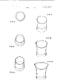
- FIGS. 2-5 show a fitting, indicated generally by the letter F, embodying a preferred form of the invention.
- the fitting F comprises a main body section having a passageway 32 therethrough defined by inner surface 34 of body wall 35 of the body 30.
- the passageway 32 is generally centered about a straight longitudinal axis 36.
- the inner surface 34 of body wall 35, and thus the internal diameter of passageway 32, is graduated from a small lower end 38, which provides an outlet 39 for the fitting, to an enlarged upper end 40, opposite outlet 39.
- This graduation is shown in FIG. 4 and in FIGS. 11-13; these figures also show that the configuration of inner surface 34 is that of a smooth curve in both horizontal and vertical planes.
- 11-13 further show that the internal diameter of passageway 32 is graduated from end 38 to end 40 in all radial directions.
- the external configuration of body 30 generally follows the same contours as the passageway 32 since the body wall 35 is of uniform thickness; this is for convenience however and does not affect the operation of the fitting.
- the fitting F also comprises two tubular members 42 and 44 having passageways 43 and 45, respectively, thercthrough.
- tubular refers to the configuration of the passageways 43 and 45 rather than to the external configuration of members 42 and 44. While it is more convenient to form members 42, 44 with walls of uniform thickness so that their external configurations follow the con tours of passageways 43, 45, any member having an appropriate passageway thcrethrough would be considered a tubular" member according to the invention.
- Tubular member 42 has a first end 46 connected to the body 30 in open communication with the passageway 32 and a second end 48 which provides an inlet 49 for the fitting.
- Tubular member 44 also has a first end 50 connected to the body 30 in open communication with the passageway 32 and a second end 52 providing another fitting inlet 53.
- the axis 54 of inlet 49 is aligned with axis 36 of passageway 32 (and outlet 38).
- Axis 56 of inlet 53 is perpendieular to axes 54 and 36.
- the lower end 58 of body 30 containing outlet 39 forms a conventional spigot for connecting fitting F to the hub end H of a pipe in a drain stack below Fitting F (see FIG. 1).
- End 48 of tubular member 42 forms a hub for receiving the spigot end S of a pipe in the drain stack above fitting F
- end 52 of tubular member 44 forms a hub for receiving the end of a horizontal pipe P from one or more plumbing fixtures such as toilets T.
- any other suitable connecting means for connecting ends 58, 48 and 52 to pipes can be used.
- a tubular member such as 44 having a horizontally dispersed inlet axis is commonly referred to as a branch and a fitting. such as the fitting F, having only one such branch. is referred to as a single branch fitting.
- passageway 43 curves outwardly with respect to axis 36 from end 48 to end 46.
- Passageway 45 curves from the generally horizontally directed end 52 to the generally vertically directed end 50.
- the first ends 50 and 46 lie adjacent each other, opening on opposite sides of axis 36, and are joined together by a common wall 60.
- the exterior of the fitting has grooves 62 adjacent wall 60.
- FIGS. 3, 4, and 6 through show that the internal cross sectional configuration of tubular member 42 gradually changes from end 48 to end 46: it becomes elongated in a direction transverse to a radius of enlarged end 40 of passageway 32, and assumes the shape of a portion of end 40 of the passageway adjacent end 46 of tubular member 42.
- Tubular member 44 undergoes a similar change in internal cross sectional configuration as shown by FIGS. 3, 4, 14 through 19, and 10.
- the terms cross section and cross sectional as used herein will refer to sections taken transverse to the direction of flow unless otherwise stated.
- FIGS. 10 and 11 By comparing FIGS. 10 and 11 it can be seen that at the intersection of the passageway 32 and the tubular members 42 and 44 (FIG. 10) the internal cross sectional configuration, exclusive of wall 60, is substantially the same as that of end 40 of passageway 32 (FIG. 11). This is because as ends 46 and 50 join together above the intersection each of them has assumed the cross sectional shape of half of the end 40 of passageway 32.
- a deflector 64 is carried by wall 60.
- the deflector 64 is a cone centered on axis 36 and having its base 66 facing the outlet 39.
- Deflector 64 has two deflecting surfaces 68 and 70 which are convex in a plane transverse to axis 36, i.e.. transverse to the general direction of the flow in the vicinity of deflector 64.
- Surface 68 is disposed so as to spray or project fluids flowing through first end 46 of tubular member 42 onto an adjoining portion 72 of inner surface 34 of body wall 35.
- Surface 70 projects fluids flowing through first end 50 of tubular member 44 onto an adjoining portion 74 of inner surface 34.
- the various fluids directing means namely, the shape and disposition of first ends 46 and 50 of the tubular members 42 and 44, the deflector 64, the wall 60, and the graduated surface 34 of body wall 35; located adjacent the intersection of the tubular members 42 and 44 and the passageway 32 cooperate to prevent plug flow through the fitting and eliminate the need for a separate vent stack with a vertical drain stack.
- the fluid directing means produce a wallhung effect in fluids flowing through passageway 32 by principles similar to those involved in the Coanda effect in fluidics.
- the first ends 46 and 50 of the tubular members being elongated transverse to radial planes of axis 36 (and therefore transverse to radii of end 40 of passageway 32) and disposed to the sides of axis 36 tend to spread fluids out along the inner surface 34 rather than dropping them through the center passageway 32. This is especially true when the first ends 46, 50 have cross sectional configurations which are substantially the same as those of the directly adjacent portions of enlarged end 40 of the passageway 32.
- the wall 60 prevents fluids flowing through the first ends 46, 50 from overshooting the central axis 36 of the passageway 32.
- the surfaces 68 and 70 spray any fluids flowing along or near wall 60 toward surface 34.
- the fluids which are thus directed against the surface 34 tend to flow along this surface as a tube of fluid.
- the surface 34 being graduated inwardly in all radial directions (going from end 40 to end 38) tends to keep the fluids which are directed onto the surface 34 attached to that surface and to catch any stray droplets or streams and cause them to be entrained in the wall hung tube.
- the fitting F of FIGS. 1-19 represents just one embodiment of a single branch fitting, and many variations are possible.
- the fitting F includes several fluid directing means for producing the wall-hung effect. However, it is not necessary that a fitting be designed to include all of these means in order to produce this effect. For example, fittings constructed as in FIGS. 1 19 but without the deflector 64 have been shown to perform satisfactorily. It is only necessary that sufficient fluid directing means be provided to eliminate plug flow problems in the particular environment in which the fitting is to be used.
- the deflector if used, need not be conical, but could be a paraboloid, a disc, or any other figure having a surface convex in a plane transverse to the flow direction. In some cases a half cone. half paraboloid or half disc, projecting from only one side of the wall 60 might suffice.
- the shape and disposition of first ends 46 and 50 of the tubular members or the shape of passageway 32 might be changed as long as a sufficient amount of the fluid was directed along the inner wall surface to prevent plug flow.
- FIGS. 20-23 show a preferred form of a double branch fitting F'.
- the fitting comprises a body 100 having a passageway 102 therethrough defined by a surface 104 of body wall 106 graduated from end to end in all radial directions.
- the lower end 108 of the body forms a spigot about an outlet 110.
- Three tubular members 112, 114 and 116 having respective passageways 118, 120 and 122 therethrough are connected to body 100 in open communication with the enlarged end 124 of passageway 102 by their respective first ends 126, 128 and 130.
- lnlets 132, 134 and 136 are provided by the second ends 138, 140 and 142 of the tubular members.
- Tubular members 114 and 116 are branches whose inlet axes 144 and 146 are horizontally disposed and whose passageways 120, 122 curve to a generally vertical direction at their first ends 128 and 130.
- Tubular member 112 is vertically directed and has an inlet flow axis 148 aligned with central axis 150 of passageway 102.
- the internal cross sectional configurations of first ends 126, 128 and 130 of the tubular members 112, 114 and 116 are elongated in directions transverse to radial planes of axis 150, and each assumes the shape of an adjacent portion of the enlarged end 124 of passageway 102. First ends 126, 128 and 130 are joined adjacent the intersection (FIG.
- First ends 126, 128, 130 are disposed to open alongside axis 150 so that axis 150 passes through the intersection of walls 152, 154, 156 rather than through one of the openings of the first ends. This disposition of first ends 126, 128, 130 and walls 152, I54, I56 with respect to axis 150 helps to spread the incoming fluids out along surface 104 and prevent them from overshooting the axis 150.
- Deflector 158 has three deflecting surfaces 160, 162 and 164 which are convex in a plane transverse to axis 150.
- Surface 160 projects fluids flowing through end 126 of member 112 toward adjoining portion 166 of surface 104.
- Surface 162 projects fluids from end 128 toward adjoining portion 168, and surface 164 projects fluids from end 130 toward adjoining portion 170 of surface 104.
- Fitting F operates in essentially the same way as fitting F.
- Fluid directing means adjacent the intersection of the three tubular members 112, 114, 116 and the passageway 102 comprise the first ends 126, 128, 130', the walls 152, 154, 156'. the deflector 158; and graduated surface 104. These fluid directing means project fluids flowing through the three tubular members toward adjoining portions of surface 104 where the fluids become wall-hung. Again many variations are possible.
- fittings according to the invention do solve plug flow problems and, in many instances, could be used in a vertical drain stack without a separate vent stack.
- wall-hanging actually does take place in fittings according to the invention was evidenced by the fact that water velocity in a stack having such fittings was less than that in similar stacks having other types of fittings. This is believed to be due to the friction between the wall and the liquid attached thereto.
- a main body section having a passageway therethrough, said passageway being defined by an inner surface of a body wall and having upper and lower ends and a central longitudinal axis, said lower end of said passageway providing an outlet for said fitting;
- tubular members each having a first end inside said fitting connected to said main body section in open communication with said upper end of said passageway, any two of said first ends being at opposite sides of a common partitioning wall lying in a plane passing through said axis of said passageway; and wherein the internal cross-sectional configuration of said first end of each of said tubular members transverse to said axis of said passageway is elongated in the general direction of said common partitioning wall;
- tubular members each have a second end providing an inlet for said fitting and wherein the flow axis of the inlet of a first one of said tubular members is substantially parallel to the flow axis of said outlet of said fitting.
- a fitting according to claim 1 further comprising a deflector supported in said fitting and having a deflecting surface convex in a plane transverse to the flow axis of said outlet, said deflecting surface being disposed so as to direct fluids flowing through the first ends of said tubular members toward a portion of the inner surface of said body wall adjoining said first ends.
- a fitting according to claim 4 wherein said deflector is cone-shaped and has its base facing and centered over said outlet.
- a fitting according to claim 3 wherein the internal cross-sectional configuration of the second end of each of said tubular members is substantially circular, and wherein said tubular members are smoothly graduated in internal cross-sectional configuration from said first ends to said second ends.
- a fitting according to claim 7 having only two such tubular members and wherein said upper end of said passageway is generally oval in cross-sectional configu- LII LII
Landscapes
- Engineering & Computer Science (AREA)
- Structural Engineering (AREA)
- Environmental & Geological Engineering (AREA)
- Health & Medical Sciences (AREA)
- Life Sciences & Earth Sciences (AREA)
- Hydrology & Water Resources (AREA)
- Public Health (AREA)
- Water Supply & Treatment (AREA)
- Quick-Acting Or Multi-Walled Pipe Joints (AREA)
Abstract
The present invention relates to fittings and in particular to a fitting comprising a hollow body section having an outlet at its lower end, tubular members connected to the upper end of the body to introduce streams of fluid into the body, fluid directing means provided in the fitting for projecting the incoming streams onto the adjacent portions of the upper part of the inner surface of the body wall so that the fluid can form a wall-hung tube as it flows through the body.
Description
United States Patent Lasater July 15, 1975 SELF-VENTING FITTING 2.476.908 7/1949 Iliadcliffe 138/39 3.268.919 8/1966 ope 4/252 R [751 Invemo Lasaie Tyle 3,346,887 10/!967 Sommer 4 21 1 [73] Assignee: Tyler Pipe Industries Inc., Tyler, 3376'397 4/1968 l 38/39 Tex 3,38l,318 5/1968 Lul t 4/2l1 [22] Filed Feb 14 1974 FOREIGN PATENTS OR APPLICATIONS 354,529 7/1905 France 4/1310. 7 [21] Appl. No; 442,452 96,345 6/1961 Denmark 285/153 Related U.S. Application Data Przmary Exammer-Henry K. Arts [63] 3:311:5 of March I972 Attorney, Agent, or Firm-Browning & Bushman 52 us. c1 4/211; 4/191; 4/252 R; [57] ABSTRACT 138/39. 138/37; 235/154 The present invention relates to fittings and in particu- 1511 1111. c1 .f E03d 9/04 fitting COmPYiSiIE a hollow sectio" [58] Field 0 Search ll l H 1/21 I. 252 19' 7; ing an outlet at its lower end, tubular members con- 285H53, '54. 3 37 5 4b 39 42 nected to the upper end Of lhfi bOdy to introduce streams of fluid into the body, fluid directing means provided in the fitting for projecting the incoming [56] References Cited t t th d t t fth t s reams on o e a acen por mm o e upper par UNITED STATES PATENTS of the inner surface of the body wall so that the fluid gamer 5/ can form a wall-hung tube as it flows through the arson l,582 845 4/1926 McArthur 4 211 x 1065.523 l2/l936 Groeniger 285/54 9 Claims, 23 Drawing Figures SHEET zanm 15 SHEET FIG. 77
FIG. I8
SELF-VENTING FITTING This is a continuation, of application Ser. No. 232,826, filed Mar. 8, I972 now abandoned.
BACKGROUND OF THE INVENTION 1. Field of the Invention The invention pertains to fittings, particularly to fittings for use in vertical drain stacks.
In joining substantially horizontal lines from one or more plumbing fixtures, such as toilets, to a vertical stack, several problems are encountered. If the lines are joined by a simple *T fitting, the flushing of toilets can cause plug flow, i.e., it can cause compact masses of water and waste to move rapidly down the drain stack. When toilets on the same floor of a building are flushed together or in close sequence. this effect is compounded. The problem can be further compounded when toilets on adjacent floors are flushed simultaneously and even more so when they are flushed in sequence. This problem can become so great that the mass of water, etc., moving down the stack acts as a piston creating a negative pressure above it and a positive pressure below it and causing water to be sucked out of the traps of fixtures above it and blown out of the traps of fixtures below it. When this happens offensive sewer gas may escape into the building. For this reason a separate vent system has previously been required in most instances.
2. Description of the Prior Art One approach to the problem is presented in U.S. Pat. No. 3,346,887 to Sommer. Sommer discloses a fitting which drops water from the horizontal line directly vertically downwardly through a mixing chamber. In the Sommer fitting the stream is diverted from the stack above the fitting from a straight path and fed into the mixing chamber at an angle so that it hits the side of the vertically falling stream from the horizontal line breaking it up and aerating it. Since the contents of the horizontal branch are dropped vertically downwardly directly over the outlet of the fitting, the problem of plug flow would appear to remain, particularly as there is no assurance that a stream of water from the stack above will happen to pass through the fitting at pre cisely the moment needed to break up the mass of water from the horizontal line.
U.S. Pat. No. 2,065,523 to Groeniger shows a fitting in which neither the horizontal nor the vertical stream is discharged directly over the outlet. However, the fit ting is merely designed to prevent turbulence and does not include means capable of preventing plug flow. The Groeniger fitting is not designed to direct fluid onto the inner walls so as to produce a wall-hung effect, but simply to direct two streams of fluid into parallel directions of flow before they are joined.
SUMMARY OF THE INVENTION It is an object of the present invention to provide a self-venting fitting having means for inducing a wallhung effect in fluids flowing therethrough.
It is another object of the present invention to provide a fitting having a fluid directing means for projecting fluids flowing through said fitting against its inner wall surface.
The instant invention solves the aforementioned plug flow problem by providing a fitting with fluid directing means adjacent the intersection of the passageway through the fitting body and an adjoining tubular member such that fluids are diverted onto the inner walls of the fitting body. The fluid directing means may include such features as the size, shape, and disposition of the end of the tubular member which is joined to the fitting body; the size and configuration of the passageway through the fitting body adjacent its intersection with the tubular member or combinations of these features. In a preferred embodiment, the fitting contains in addition a deflector supported in the fitting body. Although the operation of the fitting is not completely understood, it is believed that the fiuid directing means induce in the fluid flowing through the fitting a phenomenon similar to the Coanda effect observed in fluidics so that the fluid becomes wall-hung in the fitting.
When the wall hung effect is induced in fluid passing through the fitting, the fluid ideally forms a tube along the inner surface of the body wall of the fitting. This eliminates plug flow problems. The column of air located within the tube of water serves as a vent in the drain stack itself so that the need for a separate vent stack is eliminated.
BRIEF DESCRIPTION OF THE DRAWINGS Other objects and advantages of the invention will be made apparent by the following detailed description and the drawings wherein:
FIG. I is a diagrammatic illustration of a part of a drain stack incorporating fittings according to the invention;
FIG. 2 is an elevational view of a single branch fitting according to the invention;
FIG. 3 is an elevational view of the fitting of FIG. 2 taken at a right angle to FIG. 2 and showing internal parts in phantom;
FIG. 4 is a vertical cross section along lines 4 4 of FIG. 3;
FIG. 5 is a plan view of the fitting of FIGS. 2 4',
FIGS. 6 through 13 are horizontal cross sections of the fitting along lines 6 6 through 13 13 of FIG. 2 respectively;
FIGS. 14 through I9 are cross sections through the branch of the fitting along lines I4 14 through 19 I9 of FIG. 2 respectively;
FIG. 20 is a vertical cross section of a double branch fitting according to the invention along lines 20 20 of FIG. 21;
FIG. 21 is a vertical elevation of the fitting of FIG. 20 taken at a right angle to FIG. 20 and showing internal parts in phantom;
FIG. 22 is a plan view of the fitting of FIGS. 20 and 21; and
FIG. 23 is a horizontal cross section taken along lines 23-23 of FIG. 2I.
DESCRIPTION OF THE PREFERRED EMBODIMENTS FIGS. 2-5 show a fitting, indicated generally by the letter F, embodying a preferred form of the invention. The fitting F comprises a main body section having a passageway 32 therethrough defined by inner surface 34 of body wall 35 of the body 30. The passageway 32 is generally centered about a straight longitudinal axis 36. The inner surface 34 of body wall 35, and thus the internal diameter of passageway 32, is graduated from a small lower end 38, which provides an outlet 39 for the fitting, to an enlarged upper end 40, opposite outlet 39. This graduation is shown in FIG. 4 and in FIGS. 11-13; these figures also show that the configuration of inner surface 34 is that of a smooth curve in both horizontal and vertical planes. FIGS. 11-13 further show that the internal diameter of passageway 32 is graduated from end 38 to end 40 in all radial directions. The external configuration of body 30 generally follows the same contours as the passageway 32 since the body wall 35 is of uniform thickness; this is for convenience however and does not affect the operation of the fitting.
The fitting F also comprises two tubular members 42 and 44 having passageways 43 and 45, respectively, thercthrough. It will be understood that the word tubular as used herein with respect to members 42 and 44 refers to the configuration of the passageways 43 and 45 rather than to the external configuration of members 42 and 44. While it is more convenient to form members 42, 44 with walls of uniform thickness so that their external configurations follow the con tours of passageways 43, 45, any member having an appropriate passageway thcrethrough would be considered a tubular" member according to the invention. Tubular member 42 has a first end 46 connected to the body 30 in open communication with the passageway 32 and a second end 48 which provides an inlet 49 for the fitting. Tubular member 44 also has a first end 50 connected to the body 30 in open communication with the passageway 32 and a second end 52 providing another fitting inlet 53.
The axis 54 of inlet 49 is aligned with axis 36 of passageway 32 (and outlet 38). Axis 56 of inlet 53 is perpendieular to axes 54 and 36. As depicted in the drawings. the lower end 58 of body 30 containing outlet 39 forms a conventional spigot for connecting fitting F to the hub end H of a pipe in a drain stack below Fitting F (see FIG. 1). End 48 of tubular member 42 forms a hub for receiving the spigot end S of a pipe in the drain stack above fitting F, and end 52 of tubular member 44 forms a hub for receiving the end of a horizontal pipe P from one or more plumbing fixtures such as toilets T. However, any other suitable connecting means for connecting ends 58, 48 and 52 to pipes can be used. A tubular member such as 44 having a horizontally dispersed inlet axis is commonly referred to as a branch and a fitting. such as the fitting F, having only one such branch. is referred to as a single branch fitting.
Referring to FIG. 4 it can be seen that passageway 43 curves outwardly with respect to axis 36 from end 48 to end 46. Passageway 45 curves from the generally horizontally directed end 52 to the generally vertically directed end 50. The first ends 50 and 46 lie adjacent each other, opening on opposite sides of axis 36, and are joined together by a common wall 60. The exterior of the fitting has grooves 62 adjacent wall 60.
FIGS. 3, 4, and 6 through show that the internal cross sectional configuration of tubular member 42 gradually changes from end 48 to end 46: it becomes elongated in a direction transverse to a radius of enlarged end 40 of passageway 32, and assumes the shape of a portion of end 40 of the passageway adjacent end 46 of tubular member 42. Tubular member 44 undergoes a similar change in internal cross sectional configuration as shown by FIGS. 3, 4, 14 through 19, and 10. Note that the terms cross section and cross sectional" as used herein will refer to sections taken transverse to the direction of flow unless otherwise stated.
By comparing FIGS. 10 and 11 it can be seen that at the intersection of the passageway 32 and the tubular members 42 and 44 (FIG. 10) the internal cross sectional configuration, exclusive of wall 60, is substantially the same as that of end 40 of passageway 32 (FIG. 11). This is because as ends 46 and 50 join together above the intersection each of them has assumed the cross sectional shape of half of the end 40 of passageway 32.
A deflector 64 is carried by wall 60. The deflector 64 is a cone centered on axis 36 and having its base 66 facing the outlet 39. Deflector 64 has two deflecting surfaces 68 and 70 which are convex in a plane transverse to axis 36, i.e.. transverse to the general direction of the flow in the vicinity of deflector 64. Surface 68 is disposed so as to spray or project fluids flowing through first end 46 of tubular member 42 onto an adjoining portion 72 of inner surface 34 of body wall 35. Surface 70 projects fluids flowing through first end 50 of tubular member 44 onto an adjoining portion 74 of inner surface 34.
The various fluids directing means; namely, the shape and disposition of first ends 46 and 50 of the tubular members 42 and 44, the deflector 64, the wall 60, and the graduated surface 34 of body wall 35; located adjacent the intersection of the tubular members 42 and 44 and the passageway 32 cooperate to prevent plug flow through the fitting and eliminate the need for a separate vent stack with a vertical drain stack. Although the operation of the fitting is not completely understood. it is believed that the fluid directing means produce a wallhung effect in fluids flowing through passageway 32 by principles similar to those involved in the Coanda effect in fluidics. The first ends 46 and 50 of the tubular members, being elongated transverse to radial planes of axis 36 (and therefore transverse to radii of end 40 of passageway 32) and disposed to the sides of axis 36 tend to spread fluids out along the inner surface 34 rather than dropping them through the center passageway 32. This is especially true when the first ends 46, 50 have cross sectional configurations which are substantially the same as those of the directly adjacent portions of enlarged end 40 of the passageway 32. The wall 60 prevents fluids flowing through the first ends 46, 50 from overshooting the central axis 36 of the passageway 32. The surfaces 68 and 70 spray any fluids flowing along or near wall 60 toward surface 34. The fluids which are thus directed against the surface 34 tend to flow along this surface as a tube of fluid. The surface 34 being graduated inwardly in all radial directions (going from end 40 to end 38) tends to keep the fluids which are directed onto the surface 34 attached to that surface and to catch any stray droplets or streams and cause them to be entrained in the wall hung tube.
The fitting F of FIGS. 1-19 represents just one embodiment of a single branch fitting, and many variations are possible. The fitting F includes several fluid directing means for producing the wall-hung effect. However, it is not necessary that a fitting be designed to include all of these means in order to produce this effect. For example, fittings constructed as in FIGS. 1 19 but without the deflector 64 have been shown to perform satisfactorily. It is only necessary that sufficient fluid directing means be provided to eliminate plug flow problems in the particular environment in which the fitting is to be used.
The following examples illustrate the types of variations of the fitting F which could be possible within the scope of the invention. The deflector, if used, need not be conical, but could be a paraboloid, a disc, or any other figure having a surface convex in a plane transverse to the flow direction. In some cases a half cone. half paraboloid or half disc, projecting from only one side of the wall 60 might suffice. Similarly the shape and disposition of first ends 46 and 50 of the tubular members or the shape of passageway 32 might be changed as long as a sufficient amount of the fluid was directed along the inner wall surface to prevent plug flow.
FIGS. 20-23 show a preferred form of a double branch fitting F'. Again the fitting comprises a body 100 having a passageway 102 therethrough defined by a surface 104 of body wall 106 graduated from end to end in all radial directions. The lower end 108 of the body forms a spigot about an outlet 110. Three tubular members 112, 114 and 116 having respective passageways 118, 120 and 122 therethrough are connected to body 100 in open communication with the enlarged end 124 of passageway 102 by their respective first ends 126, 128 and 130. lnlets 132, 134 and 136 are provided by the second ends 138, 140 and 142 of the tubular members.
Fitting F operates in essentially the same way as fitting F. Fluid directing means adjacent the intersection of the three tubular members 112, 114, 116 and the passageway 102 comprise the first ends 126, 128, 130', the walls 152, 154, 156'. the deflector 158; and graduated surface 104. These fluid directing means project fluids flowing through the three tubular members toward adjoining portions of surface 104 where the fluids become wall-hung. Again many variations are possible.
Experiments have shown that fittings according to the invention do solve plug flow problems and, in many instances, could be used in a vertical drain stack without a separate vent stack. The fact that wall-hanging actually does take place in fittings according to the invention was evidenced by the fact that water velocity in a stack having such fittings was less than that in similar stacks having other types of fittings. This is believed to be due to the friction between the wall and the liquid attached thereto.
Preferred embodiments of the invention having been thus described, what is claimed is:
l. A fitting for use in a drain stack. said fitting comprising:
a main body section having a passageway therethrough, said passageway being defined by an inner surface of a body wall and having upper and lower ends and a central longitudinal axis, said lower end of said passageway providing an outlet for said fitting;
at least two tubular members each having a first end inside said fitting connected to said main body section in open communication with said upper end of said passageway, any two of said first ends being at opposite sides of a common partitioning wall lying in a plane passing through said axis of said passageway; and wherein the internal cross-sectional configuration of said first end of each of said tubular members transverse to said axis of said passageway is elongated in the general direction of said common partitioning wall;
the elongated configuration of said first ends tending to direct fluid flowing therethrough toward said inner surface of said body wall so as to be conducive to a wall-hugging effect in said fluid as it passes through said passageway of said main body section.
2. A fitting according to claim 1 wherein said tubular members each have a second end providing an inlet for said fitting and wherein the flow axis of the inlet of a first one of said tubular members is substantially parallel to the flow axis of said outlet of said fitting.
3. A fitting according to claim 2 wherein the flow axes of the inlets of the others of said tubular members are substantially normal to the flow axis of the inlet of said first one of said tubular members.
4. A fitting according to claim 1 further comprising a deflector supported in said fitting and having a deflecting surface convex in a plane transverse to the flow axis of said outlet, said deflecting surface being disposed so as to direct fluids flowing through the first ends of said tubular members toward a portion of the inner surface of said body wall adjoining said first ends.
5. A fitting according to claim 4 wherein said deflector is cone-shaped and has its base facing and centered over said outlet.
6. A fitting according to claim 3 wherein the internal cross-sectional configuration of the second end of each of said tubular members is substantially circular, and wherein said tubular members are smoothly graduated in internal cross-sectional configuration from said first ends to said second ends.
7. A fitting according to claim 1 wherein said internal cross-sectional configuration of said first end of each of said tubular members is defined by two radii of said upper end of said passageway and an included are defined by said inner surface body wall.
8. A fitting according to claim 7 having only two such tubular members and wherein said upper end of said passageway is generally oval in cross-sectional configu- LII LII
way is generally circular in cross-sectional configuration and wherein said internal cross-sectional configuration of said first end of each of said tubular members is a one-third sector of a circle.
Claims (9)
1. A fitting for use in a drain stack, said fitting comprising: a main body section having a passageway therethrough, said passageway being defined by an inner surface of a body wall and having upper and lower ends and a central longitudinal axis, said lower end of said passageway providing an outlet for said fitting; at least two tubular members each having a first end inside said fitting connected to said main body section in open communication with said upper end of said passageway, any two of said first ends being at opposite sides of a common partitioning wall lying in a plane passing through said axis of said passageway; and wherein the internal cross-sectional configuration of said first end of each of said tubular members transverse to said axis of said passageway is elongated in the general direction of said common partitioning wall; the elongated configuration of said first ends tending to direct fluid flowing therethrough toward said inner surface of said body wall so as to be conducive to a wall-hugging effect in said fluid as it passes through said passageway of said main body section.
2. A fitting according to claim 1 wherein said tubular members each have a second end pRoviding an inlet for said fitting and wherein the flow axis of the inlet of a first one of said tubular members is substantially parallel to the flow axis of said outlet of said fitting.
3. A fitting according to claim 2 wherein the flow axes of the inlets of the others of said tubular members are substantially normal to the flow axis of the inlet of said first one of said tubular members.
4. A fitting according to claim 1 further comprising a deflector supported in said fitting and having a deflecting surface convex in a plane transverse to the flow axis of said outlet, said deflecting surface being disposed so as to direct fluids flowing through the first ends of said tubular members toward a portion of the inner surface of said body wall adjoining said first ends.
5. A fitting according to claim 4 wherein said deflector is cone-shaped and has its base facing and centered over said outlet.
6. A fitting according to claim 3 wherein the internal cross-sectional configuration of the second end of each of said tubular members is substantially circular, and wherein said tubular members are smoothly graduated in internal cross-sectional configuration from said first ends to said second ends.
7. A fitting according to claim 1 wherein said internal cross-sectional configuration of said first end of each of said tubular members is defined by two radii of said upper end of said passageway and an included arc defined by said inner surface body wall.
8. A fitting according to claim 7 having only two such tubular members and wherein said upper end of said passageway is generally oval in cross-sectional configuration and wherein said internal cross-sectional configuration of said first end of each of said tubular members is a half oval.
9. A fitting according to claim 7 having three such tubular members wherein said upper end of said passageway is generally circular in cross-sectional configuration and wherein said internal cross-sectional configuration of said first end of each of said tubular members is a one-third sector of a circle.
Priority Applications (1)
| Application Number | Priority Date | Filing Date | Title |
|---|---|---|---|
| US442452A US3894302A (en) | 1972-03-08 | 1974-02-14 | Self-venting fitting |
Applications Claiming Priority (2)
| Application Number | Priority Date | Filing Date | Title |
|---|---|---|---|
| US23282672A | 1972-03-08 | 1972-03-08 | |
| US442452A US3894302A (en) | 1972-03-08 | 1974-02-14 | Self-venting fitting |
Publications (1)
| Publication Number | Publication Date |
|---|---|
| US3894302A true US3894302A (en) | 1975-07-15 |
Family
ID=26926364
Family Applications (1)
| Application Number | Title | Priority Date | Filing Date |
|---|---|---|---|
| US442452A Expired - Lifetime US3894302A (en) | 1972-03-08 | 1974-02-14 | Self-venting fitting |
Country Status (1)
| Country | Link |
|---|---|
| US (1) | US3894302A (en) |
Cited By (70)
| Publication number | Priority date | Publication date | Assignee | Title |
|---|---|---|---|---|
| US3986790A (en) * | 1974-05-31 | 1976-10-19 | Mitsubishi Jukogyo Kabushiki Kaisha | Single suction type air inlet casing of an axial-flow compressor |
| US4162546A (en) * | 1977-10-31 | 1979-07-31 | Carrcraft Manufacturing Company | Branch tail piece |
| US4480656A (en) * | 1977-05-20 | 1984-11-06 | Johnson Robert L | Plumbing fixture |
| US4569110A (en) * | 1982-06-01 | 1986-02-11 | Goettel Richard J | Self tapping duct fitting and method of use |
| US4729228A (en) * | 1986-10-20 | 1988-03-08 | American Standard Inc. | Suction line flow stream separator for parallel compressor arrangements |
| US4794956A (en) * | 1987-07-10 | 1989-01-03 | Saddle Vent Inc. | Air conduit for manhole |
| EP0376425A2 (en) * | 1988-12-30 | 1990-07-04 | Air Systems, Inc. | Apparatus for ventilating an enclosure accessed by a manhole |
| US6056014A (en) * | 1997-07-31 | 2000-05-02 | Noriatsu Kojima | Drainage collective pipe joint |
| US6371167B1 (en) * | 2000-08-30 | 2002-04-16 | Denso Corporation | Drain pipe for draining water or the like from casing |
| US6594966B2 (en) | 2001-11-06 | 2003-07-22 | Craig J. Froeter | Bi-functional roof drain and method of retrofitting a roof drainage system therewith |
| WO2003106773A1 (en) * | 2002-06-18 | 2003-12-24 | 株式会社ブリヂストン | Special joint for drain collecting pipe, draining system, and draining method |
| US20040261871A1 (en) * | 2003-06-25 | 2004-12-30 | Air Systems, Inc. Dba | Electrically conductive confined space ventilator conduit formed of conductive polymer, electrical grounding circuit for ventilation system using same, and methods of using and forming same |
| US20050104373A1 (en) * | 2003-11-14 | 2005-05-19 | Zarubaiko Ted M. | Draining and/or stagnant-pocket-minimizing instrument tee |
| US20050257845A1 (en) * | 2004-05-24 | 2005-11-24 | Kenneth Burrows | Even-flow septic tee arrangement |
| US20060231086A1 (en) * | 2005-04-19 | 2006-10-19 | Lennox Manufacturing Inc. | Distribution tee assembly |
| US20080048438A1 (en) * | 2004-11-01 | 2008-02-28 | Weise Gary K | Plumbing apparatus |
| WO2008118099A1 (en) | 2007-03-23 | 2008-10-02 | Fast Flow Limited | Junction device, system and method for fluid drainage |
| US20100101673A1 (en) * | 2008-10-24 | 2010-04-29 | Walter Cornwall | Aerator fitting having curved baffle |
| US20110186379A1 (en) * | 2010-02-03 | 2011-08-04 | Rinehart Gerald L | Muffler baffle |
| EP2525126A1 (en) * | 2011-05-20 | 2012-11-21 | NORMA Germany GmbH | Connector for a heatable fluid conduit and heatable fluid conduit |
| US20140045415A1 (en) * | 2012-08-09 | 2014-02-13 | Hamilton Sundstrand Corporation | Cabin air compressor outlet duct |
| US20140182683A1 (en) * | 2012-12-28 | 2014-07-03 | Suncoke Technology And Development Llc. | Exhaust flow modifier, duct intersection incorporating the same, and methods therefor |
| CN104358960A (en) * | 2014-10-17 | 2015-02-18 | 浙江伟星新型建材股份有限公司 | Connecting pipe fitting for stand pipe for drainage |
| USD750757S1 (en) * | 2014-11-25 | 2016-03-01 | Corpak Medsystems, Inc. | Dual material Y-connector |
| USD750759S1 (en) * | 2014-11-25 | 2016-03-01 | Corpak Medsystems, Inc. | Overmold for a Y-connector |
| USD750758S1 (en) * | 2014-11-25 | 2016-03-01 | Corpak Medsystems, Inc. | Dual material Y-connector with tethered caps |
| US9321965B2 (en) | 2009-03-17 | 2016-04-26 | Suncoke Technology And Development Llc. | Flat push coke wet quenching apparatus and process |
| US9359554B2 (en) | 2012-08-17 | 2016-06-07 | Suncoke Technology And Development Llc | Automatic draft control system for coke plants |
| USD760873S1 (en) * | 2014-11-25 | 2016-07-05 | Corpak Medsystems, Inc. | Connectors for a Y-connector |
| US9506595B2 (en) | 2011-05-20 | 2016-11-29 | Norma Germany Gmbh | Fluid line |
| US9580656B2 (en) | 2014-08-28 | 2017-02-28 | Suncoke Technology And Development Llc | Coke oven charging system |
| US9671053B2 (en) | 2011-05-20 | 2017-06-06 | Norma Germany Gmbh | Fluid line |
| US9683740B2 (en) | 2012-07-31 | 2017-06-20 | Suncoke Technology And Development Llc | Methods for handling coal processing emissions and associated systems and devices |
| US9862888B2 (en) | 2012-12-28 | 2018-01-09 | Suncoke Technology And Development Llc | Systems and methods for improving quenched coke recovery |
| US10016714B2 (en) | 2012-12-28 | 2018-07-10 | Suncoke Technology And Development Llc | Systems and methods for removing mercury from emissions |
| US10041002B2 (en) | 2012-08-17 | 2018-08-07 | Suncoke Technology And Development Llc | Coke plant including exhaust gas sharing |
| US10047295B2 (en) | 2012-12-28 | 2018-08-14 | Suncoke Technology And Development Llc | Non-perpendicular connections between coke oven uptakes and a hot common tunnel, and associated systems and methods |
| US10053627B2 (en) | 2012-08-29 | 2018-08-21 | Suncoke Technology And Development Llc | Method and apparatus for testing coal coking properties |
| US10145500B2 (en) | 2008-02-22 | 2018-12-04 | Bulk Tank, Inc | Structured tee with wear pocket |
| US10526541B2 (en) | 2014-06-30 | 2020-01-07 | Suncoke Technology And Development Llc | Horizontal heat recovery coke ovens having monolith crowns |
| US10526542B2 (en) | 2015-12-28 | 2020-01-07 | Suncoke Technology And Development Llc | Method and system for dynamically charging a coke oven |
| US10619101B2 (en) | 2013-12-31 | 2020-04-14 | Suncoke Technology And Development Llc | Methods for decarbonizing coking ovens, and associated systems and devices |
| US10760002B2 (en) | 2012-12-28 | 2020-09-01 | Suncoke Technology And Development Llc | Systems and methods for maintaining a hot car in a coke plant |
| US10851306B2 (en) | 2017-05-23 | 2020-12-01 | Suncoke Technology And Development Llc | System and method for repairing a coke oven |
| US10883051B2 (en) | 2012-12-28 | 2021-01-05 | Suncoke Technology And Development Llc | Methods and systems for improved coke quenching |
| US10927303B2 (en) | 2013-03-15 | 2021-02-23 | Suncoke Technology And Development Llc | Methods for improved quench tower design |
| US10968393B2 (en) | 2014-09-15 | 2021-04-06 | Suncoke Technology And Development Llc | Coke ovens having monolith component construction |
| US10968395B2 (en) | 2014-12-31 | 2021-04-06 | Suncoke Technology And Development Llc | Multi-modal beds of coking material |
| US11008518B2 (en) | 2018-12-28 | 2021-05-18 | Suncoke Technology And Development Llc | Coke plant tunnel repair and flexible joints |
| US11021655B2 (en) | 2018-12-28 | 2021-06-01 | Suncoke Technology And Development Llc | Decarbonization of coke ovens and associated systems and methods |
| US11060032B2 (en) | 2015-01-02 | 2021-07-13 | Suncoke Technology And Development Llc | Integrated coke plant automation and optimization using advanced control and optimization techniques |
| US11071935B2 (en) | 2018-12-28 | 2021-07-27 | Suncoke Technology And Development Llc | Particulate detection for industrial facilities, and associated systems and methods |
| US11098252B2 (en) | 2018-12-28 | 2021-08-24 | Suncoke Technology And Development Llc | Spring-loaded heat recovery oven system and method |
| US11105077B1 (en) | 2015-11-18 | 2021-08-31 | Vista Water Group, Llc | Water drain management apparatus used with autoclaves, sterilizers or other devices in a clinical facility |
| US11105076B1 (en) | 2015-11-18 | 2021-08-31 | Vista Water Group, Llc | Water drain management apparatus used with autoclaves, sterilizers or other devices in a clinical facility |
| US11142699B2 (en) | 2012-12-28 | 2021-10-12 | Suncoke Technology And Development Llc | Vent stack lids and associated systems and methods |
| US11261381B2 (en) | 2018-12-28 | 2022-03-01 | Suncoke Technology And Development Llc | Heat recovery oven foundation |
| US11395989B2 (en) | 2018-12-31 | 2022-07-26 | Suncoke Technology And Development Llc | Methods and systems for providing corrosion resistant surfaces in contaminant treatment systems |
| US11479953B1 (en) | 2020-05-19 | 2022-10-25 | Vista Water Group, Llc | Anti-backflow plumbing fitting |
| US11486572B2 (en) | 2018-12-31 | 2022-11-01 | Suncoke Technology And Development Llc | Systems and methods for Utilizing flue gas |
| US11492789B1 (en) * | 2015-11-18 | 2022-11-08 | Vista Water Group, Llc | Fluid collector for receiving fluids of different densities and providing heat exchange |
| US20220356975A1 (en) * | 2021-05-06 | 2022-11-10 | Douglas Murray | Waste Pipe Fitting Assembly |
| US11508230B2 (en) | 2016-06-03 | 2022-11-22 | Suncoke Technology And Development Llc | Methods and systems for automatically generating a remedial action in an industrial facility |
| US11624176B1 (en) * | 2015-11-18 | 2023-04-11 | Vista Water Group, Llc | Water drain management apparatus |
| US11760937B2 (en) | 2018-12-28 | 2023-09-19 | Suncoke Technology And Development Llc | Oven uptakes |
| US11767482B2 (en) | 2020-05-03 | 2023-09-26 | Suncoke Technology And Development Llc | High-quality coke products |
| US11788012B2 (en) | 2015-01-02 | 2023-10-17 | Suncoke Technology And Development Llc | Integrated coke plant automation and optimization using advanced control and optimization techniques |
| USD1002229S1 (en) * | 2020-12-21 | 2023-10-24 | Sheng Tai Brassware Co., Ltd. | Bathroom accessory |
| US11851724B2 (en) | 2021-11-04 | 2023-12-26 | Suncoke Technology And Development Llc. | Foundry coke products, and associated systems, devices, and methods |
| US11946108B2 (en) | 2021-11-04 | 2024-04-02 | Suncoke Technology And Development Llc | Foundry coke products and associated processing methods via cupolas |
Citations (9)
| Publication number | Priority date | Publication date | Assignee | Title |
|---|---|---|---|---|
| US788803A (en) * | 1905-01-09 | 1905-05-02 | Frank Walker | Sanitary drainage and vent-fitting. |
| US1186280A (en) * | 1914-07-21 | 1916-06-06 | Harry Y Carson | Fitting for plumbing systems. |
| US1582845A (en) * | 1923-03-27 | 1926-04-27 | William P Mcarthur | Adjustable drainage fitting for hanging battery wall toilets |
| US2065523A (en) * | 1934-07-20 | 1936-12-29 | Pierce John B Foundation | Method of uniting fluid streams and device therefor |
| US2476908A (en) * | 1946-09-07 | 1949-07-19 | George F Radcliffe | Double fitting for sewage pipe connections |
| US3268919A (en) * | 1963-11-18 | 1966-08-30 | Courtney C Pope | Fitting and tiling frame for wall mounted wall discharge water closet |
| US3346887A (en) * | 1965-02-11 | 1967-10-17 | Anaconda American Brass Co | Sanitary drain system, method, and fittings therefor |
| US3376897A (en) * | 1967-07-31 | 1968-04-09 | Escher Wyss Ag | Pipe branch piece |
| US3381318A (en) * | 1965-10-22 | 1968-05-07 | Hermanus N. Luijt | Plumbing fitting |
-
1974
- 1974-02-14 US US442452A patent/US3894302A/en not_active Expired - Lifetime
Patent Citations (9)
| Publication number | Priority date | Publication date | Assignee | Title |
|---|---|---|---|---|
| US788803A (en) * | 1905-01-09 | 1905-05-02 | Frank Walker | Sanitary drainage and vent-fitting. |
| US1186280A (en) * | 1914-07-21 | 1916-06-06 | Harry Y Carson | Fitting for plumbing systems. |
| US1582845A (en) * | 1923-03-27 | 1926-04-27 | William P Mcarthur | Adjustable drainage fitting for hanging battery wall toilets |
| US2065523A (en) * | 1934-07-20 | 1936-12-29 | Pierce John B Foundation | Method of uniting fluid streams and device therefor |
| US2476908A (en) * | 1946-09-07 | 1949-07-19 | George F Radcliffe | Double fitting for sewage pipe connections |
| US3268919A (en) * | 1963-11-18 | 1966-08-30 | Courtney C Pope | Fitting and tiling frame for wall mounted wall discharge water closet |
| US3346887A (en) * | 1965-02-11 | 1967-10-17 | Anaconda American Brass Co | Sanitary drain system, method, and fittings therefor |
| US3381318A (en) * | 1965-10-22 | 1968-05-07 | Hermanus N. Luijt | Plumbing fitting |
| US3376897A (en) * | 1967-07-31 | 1968-04-09 | Escher Wyss Ag | Pipe branch piece |
Cited By (120)
| Publication number | Priority date | Publication date | Assignee | Title |
|---|---|---|---|---|
| US3986790A (en) * | 1974-05-31 | 1976-10-19 | Mitsubishi Jukogyo Kabushiki Kaisha | Single suction type air inlet casing of an axial-flow compressor |
| US4480656A (en) * | 1977-05-20 | 1984-11-06 | Johnson Robert L | Plumbing fixture |
| US4162546A (en) * | 1977-10-31 | 1979-07-31 | Carrcraft Manufacturing Company | Branch tail piece |
| US4569110A (en) * | 1982-06-01 | 1986-02-11 | Goettel Richard J | Self tapping duct fitting and method of use |
| US4729228A (en) * | 1986-10-20 | 1988-03-08 | American Standard Inc. | Suction line flow stream separator for parallel compressor arrangements |
| US4982653A (en) * | 1987-07-10 | 1991-01-08 | Saddle Vent, Inc. | Method and apparatus for ventilating an enclosure accessed by a manhole |
| US4794956A (en) * | 1987-07-10 | 1989-01-03 | Saddle Vent Inc. | Air conduit for manhole |
| EP0376425A3 (en) * | 1988-12-30 | 1991-06-26 | Air Systems, Inc. | Apparatus for ventilating an enclosure accessed by a manhole |
| EP0376425A2 (en) * | 1988-12-30 | 1990-07-04 | Air Systems, Inc. | Apparatus for ventilating an enclosure accessed by a manhole |
| US6056014A (en) * | 1997-07-31 | 2000-05-02 | Noriatsu Kojima | Drainage collective pipe joint |
| US6371167B1 (en) * | 2000-08-30 | 2002-04-16 | Denso Corporation | Drain pipe for draining water or the like from casing |
| US6594966B2 (en) | 2001-11-06 | 2003-07-22 | Craig J. Froeter | Bi-functional roof drain and method of retrofitting a roof drainage system therewith |
| WO2003106773A1 (en) * | 2002-06-18 | 2003-12-24 | 株式会社ブリヂストン | Special joint for drain collecting pipe, draining system, and draining method |
| US20100210204A1 (en) * | 2003-06-25 | 2010-08-19 | Air Systems, Inc | Electrically conductive confined space ventilator conduit formed of conductive polymer, electrical grounding circuit for ventilation systems using same, and methods of using and forming same |
| US20040261871A1 (en) * | 2003-06-25 | 2004-12-30 | Air Systems, Inc. Dba | Electrically conductive confined space ventilator conduit formed of conductive polymer, electrical grounding circuit for ventilation system using same, and methods of using and forming same |
| US6843274B1 (en) * | 2003-06-25 | 2005-01-18 | Air Systems International, Inc. | Electrically conductive confined space ventilator conduit formed of conductive polymer, electrical grounding circuit for ventilation system using same, and methods of using and forming same |
| US7992593B2 (en) | 2003-06-25 | 2011-08-09 | Air Systems, Inc. | Electrically conductive confined space ventilator conduit formed of conductive polymer, electrical grounding circuit for ventilation systems using same, and methods of using and forming same |
| US20050104373A1 (en) * | 2003-11-14 | 2005-05-19 | Zarubaiko Ted M. | Draining and/or stagnant-pocket-minimizing instrument tee |
| US6991263B2 (en) * | 2003-11-14 | 2006-01-31 | Itt Manufacturing Enterprises, Inc. | Enhanced-draining and/or stagnant-pocket-minimizing instrument tee |
| US7021336B2 (en) * | 2004-05-24 | 2006-04-04 | Kenneth Burrows | Even-flow septic tee arrangement |
| US20050257845A1 (en) * | 2004-05-24 | 2005-11-24 | Kenneth Burrows | Even-flow septic tee arrangement |
| US20080048438A1 (en) * | 2004-11-01 | 2008-02-28 | Weise Gary K | Plumbing apparatus |
| US8141910B2 (en) * | 2004-11-01 | 2012-03-27 | Weise Gary K | Plumbing apparatus |
| US20060231086A1 (en) * | 2005-04-19 | 2006-10-19 | Lennox Manufacturing Inc. | Distribution tee assembly |
| EP2129840A4 (en) * | 2007-03-23 | 2012-05-16 | Fast Flow Ltd | Junction device, system and method for fluid drainage |
| AU2008230182B2 (en) * | 2007-03-23 | 2014-01-16 | Fast Flow Limited | Junction device, system and method for fluid drainage |
| WO2008118099A1 (en) | 2007-03-23 | 2008-10-02 | Fast Flow Limited | Junction device, system and method for fluid drainage |
| EP2129840A1 (en) * | 2007-03-23 | 2009-12-09 | Fast Flow Limited | Junction device, system and method for fluid drainage |
| US10145500B2 (en) | 2008-02-22 | 2018-12-04 | Bulk Tank, Inc | Structured tee with wear pocket |
| US20100101673A1 (en) * | 2008-10-24 | 2010-04-29 | Walter Cornwall | Aerator fitting having curved baffle |
| US9321965B2 (en) | 2009-03-17 | 2016-04-26 | Suncoke Technology And Development Llc. | Flat push coke wet quenching apparatus and process |
| US20110186379A1 (en) * | 2010-02-03 | 2011-08-04 | Rinehart Gerald L | Muffler baffle |
| EP2525126A1 (en) * | 2011-05-20 | 2012-11-21 | NORMA Germany GmbH | Connector for a heatable fluid conduit and heatable fluid conduit |
| CN102788207A (en) * | 2011-05-20 | 2012-11-21 | 诺马德国有限责任公司 | Connector for a heatable fluid line and heatable fluid line |
| US9671053B2 (en) | 2011-05-20 | 2017-06-06 | Norma Germany Gmbh | Fluid line |
| CN102788207B (en) * | 2011-05-20 | 2015-04-08 | 诺马德国有限责任公司 | Connector for a heatable fluid line and heatable fluid line |
| US9506595B2 (en) | 2011-05-20 | 2016-11-29 | Norma Germany Gmbh | Fluid line |
| US9464747B2 (en) | 2011-05-20 | 2016-10-11 | Norma Germany Gmbh | Connector for a heatable fluid line and heatable fluid line |
| US9683740B2 (en) | 2012-07-31 | 2017-06-20 | Suncoke Technology And Development Llc | Methods for handling coal processing emissions and associated systems and devices |
| US9440743B2 (en) * | 2012-08-09 | 2016-09-13 | Hamilton Sundstrand Corporation | Cabin air compressor outlet duct |
| US20140045415A1 (en) * | 2012-08-09 | 2014-02-13 | Hamilton Sundstrand Corporation | Cabin air compressor outlet duct |
| US10041002B2 (en) | 2012-08-17 | 2018-08-07 | Suncoke Technology And Development Llc | Coke plant including exhaust gas sharing |
| US9359554B2 (en) | 2012-08-17 | 2016-06-07 | Suncoke Technology And Development Llc | Automatic draft control system for coke plants |
| US11692138B2 (en) | 2012-08-17 | 2023-07-04 | Suncoke Technology And Development Llc | Automatic draft control system for coke plants |
| US10947455B2 (en) | 2012-08-17 | 2021-03-16 | Suncoke Technology And Development Llc | Automatic draft control system for coke plants |
| US10611965B2 (en) | 2012-08-17 | 2020-04-07 | Suncoke Technology And Development Llc | Coke plant including exhaust gas sharing |
| US11441077B2 (en) | 2012-08-17 | 2022-09-13 | Suncoke Technology And Development Llc | Coke plant including exhaust gas sharing |
| US10053627B2 (en) | 2012-08-29 | 2018-08-21 | Suncoke Technology And Development Llc | Method and apparatus for testing coal coking properties |
| US20140182683A1 (en) * | 2012-12-28 | 2014-07-03 | Suncoke Technology And Development Llc. | Exhaust flow modifier, duct intersection incorporating the same, and methods therefor |
| US11142699B2 (en) | 2012-12-28 | 2021-10-12 | Suncoke Technology And Development Llc | Vent stack lids and associated systems and methods |
| US9862888B2 (en) | 2012-12-28 | 2018-01-09 | Suncoke Technology And Development Llc | Systems and methods for improving quenched coke recovery |
| US10760002B2 (en) | 2012-12-28 | 2020-09-01 | Suncoke Technology And Development Llc | Systems and methods for maintaining a hot car in a coke plant |
| US10016714B2 (en) | 2012-12-28 | 2018-07-10 | Suncoke Technology And Development Llc | Systems and methods for removing mercury from emissions |
| US10883051B2 (en) | 2012-12-28 | 2021-01-05 | Suncoke Technology And Development Llc | Methods and systems for improved coke quenching |
| US10047295B2 (en) | 2012-12-28 | 2018-08-14 | Suncoke Technology And Development Llc | Non-perpendicular connections between coke oven uptakes and a hot common tunnel, and associated systems and methods |
| US11939526B2 (en) | 2012-12-28 | 2024-03-26 | Suncoke Technology And Development Llc | Vent stack lids and associated systems and methods |
| US11845037B2 (en) | 2012-12-28 | 2023-12-19 | Suncoke Technology And Development Llc | Systems and methods for removing mercury from emissions |
| US11359145B2 (en) | 2012-12-28 | 2022-06-14 | Suncoke Technology And Development Llc | Systems and methods for maintaining a hot car in a coke plant |
| US11117087B2 (en) | 2012-12-28 | 2021-09-14 | Suncoke Technology And Development Llc | Systems and methods for removing mercury from emissions |
| US10323192B2 (en) | 2012-12-28 | 2019-06-18 | Suncoke Technology And Development Llc | Systems and methods for improving quenched coke recovery |
| US11008517B2 (en) | 2012-12-28 | 2021-05-18 | Suncoke Technology And Development Llc | Non-perpendicular connections between coke oven uptakes and a hot common tunnel, and associated systems and methods |
| US10975309B2 (en) | 2012-12-28 | 2021-04-13 | Suncoke Technology And Development Llc | Exhaust flow modifier, duct intersection incorporating the same, and methods therefor |
| US9476547B2 (en) * | 2012-12-28 | 2016-10-25 | Suncoke Technology And Development Llc | Exhaust flow modifier, duct intersection incorporating the same, and methods therefor |
| US11807812B2 (en) | 2012-12-28 | 2023-11-07 | Suncoke Technology And Development Llc | Methods and systems for improved coke quenching |
| US11746296B2 (en) | 2013-03-15 | 2023-09-05 | Suncoke Technology And Development Llc | Methods and systems for improved quench tower design |
| US10927303B2 (en) | 2013-03-15 | 2021-02-23 | Suncoke Technology And Development Llc | Methods for improved quench tower design |
| US11359146B2 (en) | 2013-12-31 | 2022-06-14 | Suncoke Technology And Development Llc | Methods for decarbonizing coking ovens, and associated systems and devices |
| US10619101B2 (en) | 2013-12-31 | 2020-04-14 | Suncoke Technology And Development Llc | Methods for decarbonizing coking ovens, and associated systems and devices |
| US10526541B2 (en) | 2014-06-30 | 2020-01-07 | Suncoke Technology And Development Llc | Horizontal heat recovery coke ovens having monolith crowns |
| US9580656B2 (en) | 2014-08-28 | 2017-02-28 | Suncoke Technology And Development Llc | Coke oven charging system |
| US9976089B2 (en) | 2014-08-28 | 2018-05-22 | Suncoke Technology And Development Llc | Coke oven charging system |
| US10308876B2 (en) | 2014-08-28 | 2019-06-04 | Suncoke Technology And Development Llc | Burn profiles for coke operations |
| US10233392B2 (en) | 2014-08-28 | 2019-03-19 | Suncoke Technology And Development Llc | Method for optimizing coke plant operation and output |
| US10920148B2 (en) | 2014-08-28 | 2021-02-16 | Suncoke Technology And Development Llc | Burn profiles for coke operations |
| US9708542B2 (en) | 2014-08-28 | 2017-07-18 | Suncoke Technology And Development Llc | Method and system for optimizing coke plant operation and output |
| US11053444B2 (en) | 2014-08-28 | 2021-07-06 | Suncoke Technology And Development Llc | Method and system for optimizing coke plant operation and output |
| US10968393B2 (en) | 2014-09-15 | 2021-04-06 | Suncoke Technology And Development Llc | Coke ovens having monolith component construction |
| US11795400B2 (en) | 2014-09-15 | 2023-10-24 | Suncoke Technology And Development Llc | Coke ovens having monolith component construction |
| CN104358960A (en) * | 2014-10-17 | 2015-02-18 | 浙江伟星新型建材股份有限公司 | Connecting pipe fitting for stand pipe for drainage |
| USD750757S1 (en) * | 2014-11-25 | 2016-03-01 | Corpak Medsystems, Inc. | Dual material Y-connector |
| USD760873S1 (en) * | 2014-11-25 | 2016-07-05 | Corpak Medsystems, Inc. | Connectors for a Y-connector |
| USD750759S1 (en) * | 2014-11-25 | 2016-03-01 | Corpak Medsystems, Inc. | Overmold for a Y-connector |
| USD750758S1 (en) * | 2014-11-25 | 2016-03-01 | Corpak Medsystems, Inc. | Dual material Y-connector with tethered caps |
| US10975311B2 (en) | 2014-12-31 | 2021-04-13 | Suncoke Technology And Development Llc | Multi-modal beds of coking material |
| US10975310B2 (en) | 2014-12-31 | 2021-04-13 | Suncoke Technology And Development Llc | Multi-modal beds of coking material |
| US10968395B2 (en) | 2014-12-31 | 2021-04-06 | Suncoke Technology And Development Llc | Multi-modal beds of coking material |
| US11788012B2 (en) | 2015-01-02 | 2023-10-17 | Suncoke Technology And Development Llc | Integrated coke plant automation and optimization using advanced control and optimization techniques |
| US11060032B2 (en) | 2015-01-02 | 2021-07-13 | Suncoke Technology And Development Llc | Integrated coke plant automation and optimization using advanced control and optimization techniques |
| US11105077B1 (en) | 2015-11-18 | 2021-08-31 | Vista Water Group, Llc | Water drain management apparatus used with autoclaves, sterilizers or other devices in a clinical facility |
| US11492789B1 (en) * | 2015-11-18 | 2022-11-08 | Vista Water Group, Llc | Fluid collector for receiving fluids of different densities and providing heat exchange |
| US11105076B1 (en) | 2015-11-18 | 2021-08-31 | Vista Water Group, Llc | Water drain management apparatus used with autoclaves, sterilizers or other devices in a clinical facility |
| US11624176B1 (en) * | 2015-11-18 | 2023-04-11 | Vista Water Group, Llc | Water drain management apparatus |
| US11214739B2 (en) | 2015-12-28 | 2022-01-04 | Suncoke Technology And Development Llc | Method and system for dynamically charging a coke oven |
| US10526542B2 (en) | 2015-12-28 | 2020-01-07 | Suncoke Technology And Development Llc | Method and system for dynamically charging a coke oven |
| US11508230B2 (en) | 2016-06-03 | 2022-11-22 | Suncoke Technology And Development Llc | Methods and systems for automatically generating a remedial action in an industrial facility |
| US10851306B2 (en) | 2017-05-23 | 2020-12-01 | Suncoke Technology And Development Llc | System and method for repairing a coke oven |
| US11845898B2 (en) | 2017-05-23 | 2023-12-19 | Suncoke Technology And Development Llc | System and method for repairing a coke oven |
| US11760937B2 (en) | 2018-12-28 | 2023-09-19 | Suncoke Technology And Development Llc | Oven uptakes |
| US11193069B2 (en) | 2018-12-28 | 2021-12-07 | Suncoke Technology And Development Llc | Coke plant tunnel repair and anchor distribution |
| US11008518B2 (en) | 2018-12-28 | 2021-05-18 | Suncoke Technology And Development Llc | Coke plant tunnel repair and flexible joints |
| US11597881B2 (en) | 2018-12-28 | 2023-03-07 | Suncoke Technology And Development Llc | Coke plant tunnel repair and flexible joints |
| US11021655B2 (en) | 2018-12-28 | 2021-06-01 | Suncoke Technology And Development Llc | Decarbonization of coke ovens and associated systems and methods |
| US11643602B2 (en) | 2018-12-28 | 2023-05-09 | Suncoke Technology And Development Llc | Decarbonization of coke ovens, and associated systems and methods |
| US11680208B2 (en) | 2018-12-28 | 2023-06-20 | Suncoke Technology And Development Llc | Spring-loaded heat recovery oven system and method |
| US11071935B2 (en) | 2018-12-28 | 2021-07-27 | Suncoke Technology And Development Llc | Particulate detection for industrial facilities, and associated systems and methods |
| US11845897B2 (en) | 2018-12-28 | 2023-12-19 | Suncoke Technology And Development Llc | Heat recovery oven foundation |
| US11365355B2 (en) | 2018-12-28 | 2022-06-21 | Suncoke Technology And Development Llc | Systems and methods for treating a surface of a coke plant |
| US11505747B2 (en) | 2018-12-28 | 2022-11-22 | Suncoke Technology And Development Llc | Coke plant tunnel repair and anchor distribution |
| US11098252B2 (en) | 2018-12-28 | 2021-08-24 | Suncoke Technology And Development Llc | Spring-loaded heat recovery oven system and method |
| US11261381B2 (en) | 2018-12-28 | 2022-03-01 | Suncoke Technology And Development Llc | Heat recovery oven foundation |
| US11819802B2 (en) | 2018-12-31 | 2023-11-21 | Suncoke Technology And Development Llc | Methods and systems for providing corrosion resistant surfaces in contaminant treatment systems |
| US11395989B2 (en) | 2018-12-31 | 2022-07-26 | Suncoke Technology And Development Llc | Methods and systems for providing corrosion resistant surfaces in contaminant treatment systems |
| US11486572B2 (en) | 2018-12-31 | 2022-11-01 | Suncoke Technology And Development Llc | Systems and methods for Utilizing flue gas |
| US11767482B2 (en) | 2020-05-03 | 2023-09-26 | Suncoke Technology And Development Llc | High-quality coke products |
| US11767662B1 (en) * | 2020-05-19 | 2023-09-26 | Vista Water Group, Llc | Anti-backflow plumbing fitting |
| US11479953B1 (en) | 2020-05-19 | 2022-10-25 | Vista Water Group, Llc | Anti-backflow plumbing fitting |
| USD1002229S1 (en) * | 2020-12-21 | 2023-10-24 | Sheng Tai Brassware Co., Ltd. | Bathroom accessory |
| US20220356975A1 (en) * | 2021-05-06 | 2022-11-10 | Douglas Murray | Waste Pipe Fitting Assembly |
| US11851724B2 (en) | 2021-11-04 | 2023-12-26 | Suncoke Technology And Development Llc. | Foundry coke products, and associated systems, devices, and methods |
| US11946108B2 (en) | 2021-11-04 | 2024-04-02 | Suncoke Technology And Development Llc | Foundry coke products and associated processing methods via cupolas |
Similar Documents
| Publication | Publication Date | Title |
|---|---|---|
| US3894302A (en) | Self-venting fitting | |
| US6279598B1 (en) | Mixing eductor | |
| JP5101721B2 (en) | Venturi device | |
| US7954507B2 (en) | Mixing eductor | |
| US3552712A (en) | Collapsible tube valve | |
| JP3122320B2 (en) | Gas-liquid dissolution mixing equipment | |
| US5213260A (en) | Nozzle for producing laminar flow | |
| ZA200207038B (en) | Sprinklers. | |
| US3503410A (en) | Fluid amplifier | |
| US5362150A (en) | Fluid mixer | |
| JPH04214494A (en) | Apparatus for dividing and combining flow of high-consistency fiber suspension | |
| US4475691A (en) | Fluid flow directional device | |
| CA1170146A (en) | Valve coupling member | |
| US2142134A (en) | Fluid distributing and mixing device | |
| US3850197A (en) | Inspiration/expiration valve | |
| KR920700713A (en) | Particulate Dispersion Forming Device | |
| KR950009036A (en) | Vacuum valve | |
| US4131439A (en) | Device for the dedusting of dust-containing gases | |
| US3503650A (en) | Conduit for dry chemical fire extinguisher systems | |
| JPH0448811Y2 (en) | ||
| US20170113326A1 (en) | Fan nozzle | |
| JPS6334249B2 (en) | ||
| JP7197175B2 (en) | Bladeless fan in the fluid pipe | |
| JP2001248868A (en) | External wind resistant exhaust vent | |
| US3319652A (en) | Discharge orifices |