US3861663A - Clamp bar for fabrics - Google Patents
Clamp bar for fabrics Download PDFInfo
- Publication number
- US3861663A US3861663A US414264A US41426473A US3861663A US 3861663 A US3861663 A US 3861663A US 414264 A US414264 A US 414264A US 41426473 A US41426473 A US 41426473A US 3861663 A US3861663 A US 3861663A
- Authority
- US
- United States
- Prior art keywords
- bar
- piston
- air
- clamp
- cylinder
- Prior art date
- Legal status (The legal status is an assumption and is not a legal conclusion. Google has not performed a legal analysis and makes no representation as to the accuracy of the status listed.)
- Expired - Lifetime
Links
Images
Classifications
-
- B—PERFORMING OPERATIONS; TRANSPORTING
- B25—HAND TOOLS; PORTABLE POWER-DRIVEN TOOLS; MANIPULATORS
- B25B—TOOLS OR BENCH DEVICES NOT OTHERWISE PROVIDED FOR, FOR FASTENING, CONNECTING, DISENGAGING OR HOLDING
- B25B5/00—Clamps
- B25B5/06—Arrangements for positively actuating jaws
- B25B5/061—Arrangements for positively actuating jaws with fluid drive
-
- A—HUMAN NECESSITIES
- A41—WEARING APPAREL
- A41H—APPLIANCES OR METHODS FOR MAKING CLOTHES, e.g. FOR DRESS-MAKING OR FOR TAILORING, NOT OTHERWISE PROVIDED FOR
- A41H43/00—Other methods, machines or appliances
- A41H43/005—Cloth spreading or piling apparatus in view of its cutting
-
- B—PERFORMING OPERATIONS; TRANSPORTING
- B25—HAND TOOLS; PORTABLE POWER-DRIVEN TOOLS; MANIPULATORS
- B25B—TOOLS OR BENCH DEVICES NOT OTHERWISE PROVIDED FOR, FOR FASTENING, CONNECTING, DISENGAGING OR HOLDING
- B25B5/00—Clamps
- B25B5/16—Details, e.g. jaws, jaw attachments
- B25B5/163—Jaws or jaw attachments
Definitions
- the clamps are operated by com- [56] References Cited pressed air, and each is actuated to clamp the fabric by pressing it manually toward its operative position, UNITED STATES PATENTS whereupon the compressed air takes over to hold it in 1,501,044 7/1924 Dwoirln 38/108 iti All of the da ps may be released simulta- 2,269,328 1/1942 Williamson 269/26 X neously by pressing a pushbutton va]ve 2,323,770 7/1943 Hazelton 269/221 X 2,327,920 8/1943 Moohl;
- Clamp bars of this general type are used, for example, to insure parallelism of a cut or hemmed edge of a drapery panel in relation to a previously cut or hemmed opposite edge.
- the difficulties of handling very large sheets of fabric under these circumstances are well known.
- the edge to be cut or hemmed may be 32 feet long or even longer.
- the present device has been conceived primarily for use in drapery forming operations, it will be readily apparent that it has general applicability in many fields.
- a principal object of the present invention is the provision of a fabric clamp bar consisting of a bar along which an edge of a large sheet of fabric may be arranged in an accurately straight line, and a series of clamps carried in spaced relation along the length of said bar and each operable to clamp the fabric to the bar.
- Another object is the provision of a clamp bar of the character described in which the clamps are compressed air-actuated, but may be individually actuated simply by pressing each clamp toward its operative position against a spring, the compressed air taking over automatically at a predetermined point to complete the setting of the clamp. In this manner, the operator may use one hand to align that portion of the fabric to be engaged by a particular clamp, and the other hand to actuate the clamp.
- a further object is the provision of a fabric clamp bar of the character described wherein the clamps, though individually actuated, may be released simultaneously simply by pressing a pushbutton.
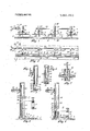
- FIG. 1 is a front elevational view of a portion of a fabric clamp bar embodying the present invention
- FIG. 2 is a top plan view of the fabric clamp bar as shown in FIG. 1,
- FIG. 3 is an enlarged sectional view taken on line III- III of FIG. 1, showing one of the clamps in its released position,
- FIG. 4 is a fragmentary view similar to FIG. 3, with the clamp at an intermediate stage in the actuation thereof,
- FIG. 5 is a view similar to FIG. 3, showing the clamp fully engaged
- FIG. 6 is a fragmentary sectional view taken on line VI-Vl of FIG. 4, and
- FIG. 7 is an enlarged sectional view taken on line VII- VII of FIG. 2.
- the numeral 2 applies to a table or other supporting surface over which it may be desired to draw a large sheet of fabric 4 by means of a clamp bar device indicated generally by the numeral 6, and consisting of an elongated base bar 8 lying on and movable over the table surface, and means for clamping an edge of the fabric to said bar.
- the base bar may be mounted on and movable over the table surface, usually by power means insuring parallelism of the bar to an edge of the table, but such bar mounting and moving means are not pertinent to the present invention, and are not shown.
- the base bar is provided with a longitudinally extending, forwardly facing shoulder 10 against which an edge of fabric 4 may be drawn to insure straight, linear positioning of said fabric edge, the top surface of the bar providing a horizontal ledge 12 forwardly of shoulder 10, with its extreme forward edge portion being bevelled as indicated at 14.
- the fabric 4 is adapted to be clamped to ledge 12 by means of a series of foot bars 16 arranged parallel to base bar 8 thereabove, said foot bars being disposed directly above ledge 12 and spaced in a series along base bar 8.
- Each foot bar may be about 9 inches long, with 2 inches between adjacent ends thereof, although this spacing is of course optional. Clamp bars 30 to 40 feet long are not uncommon.
- Each foot bar is rigid, though it may be covered with a smooth plastic material, not shown, to prevent snagging or tearing of the fabric, and
- Each foot bar 16 is supported by a vertically yieldable spring yoke 18 from the forward end of a rigid horizontal arm 20, said arm extending rearwardly from said yoke and entering a vertically elongated slot 22 formed in a tubular post 24, said post being fixed at its lower end in bar 8 behind shoulder 10 thereof.
- Said post acts as a pneumatic cylinder, and is sealed at its upper end.
- the rearward end of the associated arm 20 is affixed, as by set screw 26, in the lower end of a pneumatic piston 28 carried operably in said post.
- Said piston' is biased upwardly in the post by a compression spring 30.
- the upper portion of the piston is bored out as indicated at 32 to be hollow, and is provided with a side air passage 34 at the bottom of the bore thereof. Air passage 34 cooperates with a vertically elongated vent slot 36 formed in the wall of post 24, in a manner to be described.
- Each post 24 is also provided with a side air inlet port 38 spaced below the upper end thereof, the ports 38 of all of the posts being interconnected by branch pipes 40 with a common air supply pipe 42 which extends horizontally behind posts 24 the full length of the base bar.
- pipe 42 is connected through a pressure release valve 44 to a pipe 46, which in turn is connected by a hose 48 to any suitable source of compressed air, not shown.
- Hose 48 is flexible to permit ready movement of the base bar over the table.
- release valve 44 includes a valve body 50 having therein a slidable plunger 52 having a passageway 54.
- the plunger is normally biased by spring 56 to the position shown, wherein passageway 54 interconnects pipes 46 and 42, but may be moved against spring 56 by manual pushbutton 58 to a position in which pipe 46 is sealed off, and passageway 54 interconnects pipe 42 to a vent hole 60 formed in the valve body, whereby pipe 42 is vented to the atmosphere.
- each clamp when each clamp is released, it has the position shown in FIG. 3, the foot bar 16 thereof being spaced well above ledge 12 of the base bar, being elevated and retained in this position by spring 30, with arm 20 engaged in the upper end of post slot 22.
- the cylinder inlet port 38 is sealed off by the piston, so that the piston is not lowered, and piston air passage 34 is in communication with post vent slot 36, so that any air which might leak past the piston is vented to the atmosphere.
- the operator then arranges fabric 4 beneath the foot bar, bringing the fabric edge into contact with shoulder of the base bar, and then actuates the clamp to lower the foot bar 16 against the fabric as in FIG. 5.
- spring yoke 18 has yielded to some degree. This yieldability of the yoke permits the foot bar to better adapt to the fabric surface, for example if the fabric is folded, and also prevents possible injury to the operator in the event he has a finger under the foot bar as the piston is lowered past the FIG. 4 position. It will thus be seen that each clamp may be actuated separately as needed, and this is considered to be advantageous singe large sheets of pliable fabric are notoriously hard to handle, and the present arrangement permits it to be positioned one section at a time proceeding from one end of a long edge, with each section being clamped in place as it is positioned.
- the clamps are all released simultaneously by momentary pressure on pushbutton 58 of release valve 44. This vents all of the air cylinder posts to the atmosphere, so that the pistons are elevated by springs 30. During the initial portion of the rise of each piston, until it is raised to the FIG. 4 position, air is vented through ports 38. At the FIG. 4 position, the piston seals port 38, but piston passage 34 then interconnects with slot 36, so that the piston can complete its upward movement with no possibility that impeding air pressure can form thereabove.
- a clamp bar for engaging an edge portion of a sheet of fabric comprising:
- a series of clamp devices mounted on said base bar in spaced relation therealong and each including a foot bar movable between an elevated position well above said base bar and a lowered position wherein it clamps said fabric against said base bar, and
- operating means operable to move said foot bars selectively between said elevated and lowered positions, said operating means for each foot bar including power means operable when actuated to lower said foot bar to its lowered position, and means operable by manual lowering of said foot bar a predetermined proportion of its travel to said lowered position to actuate said power means.
- a clamp bar as recited in claim I wherein said power means for each of said clamp devices comprises:
- air pressure-actuated means operable when supplied with air under pressure to lower said foot bar to its lowered position
- air pressure control means operable by manual lowering of said foot bar through a portion of its movement, against said spring means, to supply air under pressure to said air pressure-actuated means
- each of said clamp devices and its operating means comprises:
- a vertical pneumatic cylinder fixed at its lower end in said base bar and sealed at its upper end.
- a piston vertically movable in said cylinder 0. an arm fixed to said piston and projecting outwardly through a vertically elongated slot of said cylinder, the associated foot bar being carried at the outer end of said arm, and
- spring means biasing said piston upwardly in said cylinder to raise said foot bar to its elevated position
- said cylinder being provided with an air inlet port connected to a source of air under pressure, said inlet port being sealed by said piston when in said elevated position but opened to supply air to said cylinder above said piston when said piston is moved manually downwardly against said spring means a predetermined portion of its travel to its lowered position.
- a clamp bar as recited in claim 4 wherein said piston is provided with an air passage opening into said cylinder above said piston and through a side of the piston below the upper end thereof, said cylinder having a side vent opening below said inlet port which cooperates with the side opening of said piston air passage to seal said piston air passage at all positions of the upper end of said piston at or below said inlet port, and to vent said piston passage to the atmosphere at all positions of the upper end of said piston above said inlet port.
- valve means biasing said valve to a first position in which the inlet and outlet thereof are interconnected and said atmospheric vent is sealed, and manually operable means for moving said valve to a second position in which said outlet and vent are interconnected, and said inlet is sealed.
Landscapes
- Engineering & Computer Science (AREA)
- Mechanical Engineering (AREA)
- Textile Engineering (AREA)
- Treatment Of Fiber Materials (AREA)
Abstract
A clamp bar for fabrics consisting of a straight bar having a straight top shoulder to which the edge of a large sheet of fabric may be drawn, and a series of clamps carried at intervals along the bar for clamping the fabric thereto. The clamps are operated by compressed air, and each is actuated to clamp the fabric by pressing it manually toward its operative position, whereupon the compressed air takes over to hold it in position. All of the clamps may be released simultaneously by pressing a pushbutton valve.
Description
I mted States Patent [191 [111 3,861,663 Strickland Jan. 21, 1975 CLAMP BAR FOR FABRICS 3,095,190 6/1963 Freund 269/32 x [76] Invento Robert V. Stric and, 9021 Wedd 3,306,603 2/1967 21ers 269/91 Overland Park, Kans. 66212 Primary Examiner Roy Lake [22] Filed: Nov. 9, 1973 Assistant Examiner-Mark S. Biclts [211 App]. NOI: 414,264 Attorney, Agent, or Firm-John A. Hamilton 52 U S Cl 26 26 8 91 269 I [57] ABSTRACT 1 9/ 3 4 A clamp bar for fabrics consisting of a straight bar [51] Int CI B25) /06 having a straight top shoulder to which the edge of a [58] Fie'ld 91 large sheet of fabric may be drawn, and a series of 269/ 32 34 clamps carried at intervals along the bar for clamping the fabric thereto. The clamps are operated by com- [56] References Cited pressed air, and each is actuated to clamp the fabric by pressing it manually toward its operative position, UNITED STATES PATENTS whereupon the compressed air takes over to hold it in 1,501,044 7/1924 Dwoirln 38/108 iti All of the da ps may be released simulta- 2,269,328 1/1942 Williamson 269/26 X neously by pressing a pushbutton va]ve 2,323,770 7/1943 Hazelton 269/221 X 2,327,920 8/1943 Moohl..... 269/32 X 8 Claims, 7 Drawing Figures O R J5 4 135 2 16 as 1 m c (Q) j x I z i 5 2 2 a ,0 J /Z 4 Z d CLAMP BAR FOR FABRICS This invention relates to new and useful improvements in fabric handling equipment, and has particular reference to a device for clamping an edge of a large sheet of fabric to a straight bar, so that the fabric may be drawn across a supporting surface, such as a large table, so that operations such as cutting, hemming, or the like may be performed on its opposite edge with the assurance that the edge on which said operations are being performed is truly parallel to the clamped edge. Clamp bars of this general type are used, for example, to insure parallelism of a cut or hemmed edge of a drapery panel in relation to a previously cut or hemmed opposite edge. The difficulties of handling very large sheets of fabric under these circumstances are well known. In draperies, the edge to be cut or hemmed may be 32 feet long or even longer. But while the present device has been conceived primarily for use in drapery forming operations, it will be readily apparent that it has general applicability in many fields.
A principal object of the present invention is the provision of a fabric clamp bar consisting of a bar along which an edge of a large sheet of fabric may be arranged in an accurately straight line, and a series of clamps carried in spaced relation along the length of said bar and each operable to clamp the fabric to the bar.
Another object is the provision of a clamp bar of the character described in which the clamps are compressed air-actuated, but may be individually actuated simply by pressing each clamp toward its operative position against a spring, the compressed air taking over automatically at a predetermined point to complete the setting of the clamp. In this manner, the operator may use one hand to align that portion of the fabric to be engaged by a particular clamp, and the other hand to actuate the clamp.
A further object is the provision of a fabric clamp bar of the character described wherein the clamps, though individually actuated, may be released simultaneously simply by pressing a pushbutton.
Other objects are simplicity and economy of construction, efficiency and dependability of operation, and adaptability for use in a wide variety of applications.
With these objects in view, as well as other objects which will appear in the course of the specification, reference will be had to the accompanying drawing, wherein:
FIG. 1 is a front elevational view of a portion of a fabric clamp bar embodying the present invention,
FIG. 2 is a top plan view of the fabric clamp bar as shown in FIG. 1,
FIG. 3 is an enlarged sectional view taken on line III- III of FIG. 1, showing one of the clamps in its released position,
FIG. 4 is a fragmentary view similar to FIG. 3, with the clamp at an intermediate stage in the actuation thereof,
FIG. 5 is a view similar to FIG. 3, showing the clamp fully engaged,
FIG. 6 is a fragmentary sectional view taken on line VI-Vl of FIG. 4, and
FIG. 7 is an enlarged sectional view taken on line VII- VII of FIG. 2.
Like reference numerals apply to similar parts throughout the several views, and the numeral 2 applies to a table or other supporting surface over which it may be desired to draw a large sheet of fabric 4 by means of a clamp bar device indicated generally by the numeral 6, and consisting of an elongated base bar 8 lying on and movable over the table surface, and means for clamping an edge of the fabric to said bar. The base bar may be mounted on and movable over the table surface, usually by power means insuring parallelism of the bar to an edge of the table, but such bar mounting and moving means are not pertinent to the present invention, and are not shown. The base bar is provided with a longitudinally extending, forwardly facing shoulder 10 against which an edge of fabric 4 may be drawn to insure straight, linear positioning of said fabric edge, the top surface of the bar providing a horizontal ledge 12 forwardly of shoulder 10, with its extreme forward edge portion being bevelled as indicated at 14.
The fabric 4 is adapted to be clamped to ledge 12 by means of a series of foot bars 16 arranged parallel to base bar 8 thereabove, said foot bars being disposed directly above ledge 12 and spaced in a series along base bar 8. Each foot bar may be about 9 inches long, with 2 inches between adjacent ends thereof, although this spacing is of course optional. Clamp bars 30 to 40 feet long are not uncommon. Each foot bar is rigid, though it may be covered with a smooth plastic material, not shown, to prevent snagging or tearing of the fabric, and
is movable downwardly from an elevated position well above ledge 12, as shown in FIG. 3, to a position clamping fabric 4 against ledge 12, as shown in FIG. 5.
Each foot bar 16 is supported by a vertically yieldable spring yoke 18 from the forward end of a rigid horizontal arm 20, said arm extending rearwardly from said yoke and entering a vertically elongated slot 22 formed in a tubular post 24, said post being fixed at its lower end in bar 8 behind shoulder 10 thereof. Said post acts as a pneumatic cylinder, and is sealed at its upper end. Within each post, the rearward end of the associated arm 20 is affixed, as by set screw 26, in the lower end of a pneumatic piston 28 carried operably in said post. Said piston'is biased upwardly in the post by a compression spring 30. The upper portion of the piston is bored out as indicated at 32 to be hollow, and is provided with a side air passage 34 at the bottom of the bore thereof. Air passage 34 cooperates with a vertically elongated vent slot 36 formed in the wall of post 24, in a manner to be described. Each post 24 is also provided with a side air inlet port 38 spaced below the upper end thereof, the ports 38 of all of the posts being interconnected by branch pipes 40 with a common air supply pipe 42 which extends horizontally behind posts 24 the full length of the base bar. At one end of the base bar, pipe 42 is connected through a pressure release valve 44 to a pipe 46, which in turn is connected by a hose 48 to any suitable source of compressed air, not shown. Hose 48 is flexible to permit ready movement of the base bar over the table.
As best shown in FIG. 7, release valve 44 includes a valve body 50 having therein a slidable plunger 52 having a passageway 54. The plunger is normally biased by spring 56 to the position shown, wherein passageway 54 interconnects pipes 46 and 42, but may be moved against spring 56 by manual pushbutton 58 to a position in which pipe 46 is sealed off, and passageway 54 interconnects pipe 42 to a vent hole 60 formed in the valve body, whereby pipe 42 is vented to the atmosphere.
In operation, it will be seen that when each clamp is released, it has the position shown in FIG. 3, the foot bar 16 thereof being spaced well above ledge 12 of the base bar, being elevated and retained in this position by spring 30, with arm 20 engaged in the upper end of post slot 22. In this position, the cylinder inlet port 38 is sealed off by the piston, so that the piston is not lowered, and piston air passage 34 is in communication with post vent slot 36, so that any air which might leak past the piston is vented to the atmosphere. The operator then arranges fabric 4 beneath the foot bar, bringing the fabric edge into contact with shoulder of the base bar, and then actuates the clamp to lower the foot bar 16 against the fabric as in FIG. 5.
To actuate the clamp, the operator first manually lowers the foot bar against the pressure of spring 30, for example by pressing downwardly on arm 20, to the position shown in FIG. 4. This movement may be very easily accomplished, since piston passage 34 is still in communication with slot 36 so that no vacuum can form above the piston, and since spring 30 need be no stronger than is required to elevate and support the weight of the associated piston 28, arm 20, spring yoke 18 and foot bar 16. At the FIG. 4 position, piston passage 34 passes beyond post slot 36 and is sealed off, and the piston uncovers port 38, so that compressed air enters the post above the piston and forces said piston downwardly until foot bar 16 clamps fabric 4 firmly against ledge 12 as in FIG. 5. The downward motion of arm 20 is limited by engagement thereof in the lower end of slot 22. In the FIG. 5 position, it will be seen that spring yoke 18 has yielded to some degree. This yieldability of the yoke permits the foot bar to better adapt to the fabric surface, for example if the fabric is folded, and also prevents possible injury to the operator in the event he has a finger under the foot bar as the piston is lowered past the FIG. 4 position. It will thus be seen that each clamp may be actuated separately as needed, and this is considered to be advantageous singe large sheets of pliable fabric are notoriously hard to handle, and the present arrangement permits it to be positioned one section at a time proceeding from one end of a long edge, with each section being clamped in place as it is positioned.
The clamps are all released simultaneously by momentary pressure on pushbutton 58 of release valve 44. This vents all of the air cylinder posts to the atmosphere, so that the pistons are elevated by springs 30. During the initial portion of the rise of each piston, until it is raised to the FIG. 4 position, air is vented through ports 38. At the FIG. 4 position, the piston seals port 38, but piston passage 34 then interconnects with slot 36, so that the piston can complete its upward movement with no possibility that impeding air pressure can form thereabove.
While I have shown and described a specific embodiment of my invention, it will be readily apparent that many minor changes of structure and operation could be made without departing from the spirit of the inventron.
What I claim as new and desire to protect by Letters Patent is:
l. A clamp bar for engaging an edge portion of a sheet of fabric comprising:
a. an elongated base bar over which the edge portion of said fabric sheet may be laid,
b. a series of clamp devices mounted on said base bar in spaced relation therealong and each including a foot bar movable between an elevated position well above said base bar and a lowered position wherein it clamps said fabric against said base bar, and
0. operating means operable to move said foot bars selectively between said elevated and lowered positions, said operating means for each foot bar including power means operable when actuated to lower said foot bar to its lowered position, and means operable by manual lowering of said foot bar a predetermined proportion of its travel to said lowered position to actuate said power means.
2. A clamp bar as recited in claim I wherein said power means for each of said clamp devices comprises:
a. spring means normally biasing the associated foot bar to its elevated position,
b. air pressure-actuated means operable when supplied with air under pressure to lower said foot bar to its lowered position,
c. air pressure control means operable by manual lowering of said foot bar through a portion of its movement, against said spring means, to supply air under pressure to said air pressure-actuated means, and
d. manually operable means for exhausting air from said air-pressure actuated means.
3. A clamp bar as recited in claim 2 wherein said manually operable means for exhausting air from said air pressure-actuated means is operable to exhaust air simultaneously from the air-pressure actuated means of all of said clamp devices.
4. A clamp bar as recited in claim 1 wherein each of said clamp devices and its operating means comprises:
a. a vertical pneumatic cylinder fixed at its lower end in said base bar and sealed at its upper end.
b. a piston vertically movable in said cylinder 0. an arm fixed to said piston and projecting outwardly through a vertically elongated slot of said cylinder, the associated foot bar being carried at the outer end of said arm, and
d. spring means biasing said piston upwardly in said cylinder to raise said foot bar to its elevated position, said cylinder being provided with an air inlet port connected to a source of air under pressure, said inlet port being sealed by said piston when in said elevated position but opened to supply air to said cylinder above said piston when said piston is moved manually downwardly against said spring means a predetermined portion of its travel to its lowered position.
5. A clamp bar as recited in claim 4 wherein said foot bar is connected to the outer end of said arm by means of a vertically yieldable spring.
6. A clamp bar as recited in claim 4 wherein said piston is provided with an air passage opening into said cylinder above said piston and through a side of the piston below the upper end thereof, said cylinder having a side vent opening below said inlet port which cooperates with the side opening of said piston air passage to seal said piston air passage at all positions of the upper end of said piston at or below said inlet port, and to vent said piston passage to the atmosphere at all positions of the upper end of said piston above said inlet port.
common conduit, and an atmospheric vent, spring means biasing said valve to a first position in which the inlet and outlet thereof are interconnected and said atmospheric vent is sealed, and manually operable means for moving said valve to a second position in which said outlet and vent are interconnected, and said inlet is sealed.
Claims (8)
1. A clamp bar for engaging an edge portion of a sheet of fabric comprising: a. an elongated base bar over which the edge portion of said fabric sheet may be laid, b. a series of clamp devices mounted on said base bar in spaced relation therealong and each including a foot bar movable between an elevated position well above said base bar and a lowered position wherein it clamps said fabric against said base bar, and c. operating means operable to move said foot bars selectively between said elevated and lowered positions, said operating means for each foot bar including power means operable when actuated to lower said foot bar to its lowered position, and means operable by manual lowering of said foot bar a predetermined proportion of its travel to said lowered position to actuate said power means.
2. A clamp bar as recited in claim 1 wherein said power means for each of said clamp devices comprises: a. spring means normally biasing the associated foot bar to its elevated position, b. air pressure-actuated means operable when supplied with air under pressure to lower said foot bar to its lowered position, c. air pressure control means operable by manual lowering of said foot bar through a portion of its movement, against said spring means, to supply air under pressure to said air pressure-actuated means, and d. manually operable means for exhausting air from said air-pressure actuated means.
3. A clamp bar as recited in claim 2 wherein said manually operable means for exhausting air from said air pressure-actuated means is operable to exhaust air simultaneously from the air-pressure actuated means of all of said clamp devices.
4. A clamp bar as recited in claim 1 wherein each of said clamp devices and its operating means comprises: a. a vertical pneumatic cylinder fixed at its lower end in said base bar and sealed at its upper end. b. a piston vertically movable in said cylinder c. an arm fixed to said piston and projecting outwardly through a vertically elongated slot of said cylinder, the associated foot bar being carried at the outer end of said arm, and d. spring means biasing said piston upwardly in said cylinder to raise said foot bar to its elevated position, said cylinder being provided with an air inlet port connected to a source of air under pressure, said inlet port being sealed by said piston when in said elevated position but opened to supply air to said cylinder above said piston when said piston is moved manually downwardly against said spring means a predetermined portion of its travel to its lowered position.
5. A clamp bar as recited in claim 4 wherein said foot bar is connected to the outer end of said arm by means of a vertically yieldable spring.
6. A clamp bar as recited in claim 4 wherein said piston is provided with an air passage opening into said cylinder above said piston and through a side of the piston below the upper end thereof, said cylinder having a side vent opening below said inlet port which cooperates with the side opening of said piston air passage to seal said piston air passage at all positions of the upper end of said piston at or below said inlet port, and to vent said piston passage to the atmosphere at all positions of the upper end of said piston above said inlet port.
7. A clamp bar as recited in claim 4 wherein compressed air from a suitable source is supplied to the inlet ports of all of said cylinders through a common conduit, and with the addition of release means manually operable to release air from said common conduit.
8. A clamp bar as recited in claim 7 wherein said release means comprises a valve having an inlet connected to said air source, an outlet connected to said common conduit, and an atmospheric vent, spring means biasing said valve to a first position in which the inlet and outlet thereof are interconnected and said atmospheric vent is sealed, and manually operable means for moving said valve to a second position in which said outlet and vent are interconnected, and said inlet is sealed.
Priority Applications (1)
| Application Number | Priority Date | Filing Date | Title |
|---|---|---|---|
| US414264A US3861663A (en) | 1973-11-09 | 1973-11-09 | Clamp bar for fabrics |
Applications Claiming Priority (1)
| Application Number | Priority Date | Filing Date | Title |
|---|---|---|---|
| US414264A US3861663A (en) | 1973-11-09 | 1973-11-09 | Clamp bar for fabrics |
Publications (1)
| Publication Number | Publication Date |
|---|---|
| US3861663A true US3861663A (en) | 1975-01-21 |
Family
ID=23640682
Family Applications (1)
| Application Number | Title | Priority Date | Filing Date |
|---|---|---|---|
| US414264A Expired - Lifetime US3861663A (en) | 1973-11-09 | 1973-11-09 | Clamp bar for fabrics |
Country Status (1)
| Country | Link |
|---|---|
| US (1) | US3861663A (en) |
Cited By (8)
| Publication number | Priority date | Publication date | Assignee | Title |
|---|---|---|---|---|
| US20030070773A1 (en) * | 1996-10-29 | 2003-04-17 | Whittemore Jeffrey P. | Partition mount |
| US20040065799A1 (en) * | 2002-08-15 | 2004-04-08 | Whittemore Jeffrey P. | Partition mount with extended-length head |
| US20050247414A1 (en) * | 2004-05-10 | 2005-11-10 | Whittemore Jeffrey P | Partition mount with integrated plunger assembly |
| US7810771B1 (en) | 2006-11-17 | 2010-10-12 | Fastcap, LLC | Systems and methods for attaching barrier sheet material to extensible pole assemblies |
| US9663962B1 (en) | 2014-01-17 | 2017-05-30 | Zipwall, Llc. | Pole mount and methods of installation and application |
| US10081955B2 (en) | 2015-07-24 | 2018-09-25 | Zipwall, Llc. | Partition mount system including head coupler with adjustable head length and head position |
| US10428539B2 (en) | 2015-06-03 | 2019-10-01 | Zipwall, Llc. | Mounting unit for partition mount |
| US10781597B2 (en) | 2015-12-28 | 2020-09-22 | Zipwall, Llc | Self-closing entryway partition |
Citations (6)
| Publication number | Priority date | Publication date | Assignee | Title |
|---|---|---|---|---|
| US1501044A (en) * | 1923-10-04 | 1924-07-15 | Dwoirin Max | Plait holder |
| US2269328A (en) * | 1939-01-09 | 1942-01-06 | Bliss E W Co | Hydraulic hold-down |
| US2323770A (en) * | 1942-11-03 | 1943-07-06 | Cincinnati Shaper Co | Hold-down means for shears and the like |
| US2327920A (en) * | 1941-07-25 | 1943-08-24 | Motch Merryweather Machinery | Metal sawing machine |
| US3095190A (en) * | 1960-09-10 | 1963-06-25 | Hilma G M B H Maschf | Pneumatic hydraulic vise |
| US3306603A (en) * | 1965-03-19 | 1967-02-28 | Mfg Specialties Co Inc | Holding apparatus for sheet material |
-
1973
- 1973-11-09 US US414264A patent/US3861663A/en not_active Expired - Lifetime
Patent Citations (6)
| Publication number | Priority date | Publication date | Assignee | Title |
|---|---|---|---|---|
| US1501044A (en) * | 1923-10-04 | 1924-07-15 | Dwoirin Max | Plait holder |
| US2269328A (en) * | 1939-01-09 | 1942-01-06 | Bliss E W Co | Hydraulic hold-down |
| US2327920A (en) * | 1941-07-25 | 1943-08-24 | Motch Merryweather Machinery | Metal sawing machine |
| US2323770A (en) * | 1942-11-03 | 1943-07-06 | Cincinnati Shaper Co | Hold-down means for shears and the like |
| US3095190A (en) * | 1960-09-10 | 1963-06-25 | Hilma G M B H Maschf | Pneumatic hydraulic vise |
| US3306603A (en) * | 1965-03-19 | 1967-02-28 | Mfg Specialties Co Inc | Holding apparatus for sheet material |
Cited By (36)
| Publication number | Priority date | Publication date | Assignee | Title |
|---|---|---|---|---|
| US20090071614A1 (en) * | 1996-10-29 | 2009-03-19 | Zipwall Llc | Partition mount |
| US7108040B2 (en) | 1996-10-29 | 2006-09-19 | Jeffrey P. Whittemore | Partition mount |
| US20040200585A1 (en) * | 1996-10-29 | 2004-10-14 | Whittemore Jeffrey P. | Partition mount |
| US6942004B2 (en) * | 1996-10-29 | 2005-09-13 | Zipwall, Llc | Partition mount |
| US6953076B2 (en) | 1996-10-29 | 2005-10-11 | Zipwall Llc | Partition mount |
| US20080006374A1 (en) * | 1996-10-29 | 2008-01-10 | Zipwall Llc | Partition mount |
| US20050284591A1 (en) * | 1996-10-29 | 2005-12-29 | Whittemore Jeffrey P | Partition mount |
| US20100301000A1 (en) * | 1996-10-29 | 2010-12-02 | Zipwall, Llc. | Partition mount |
| US20060272785A1 (en) * | 1996-10-29 | 2006-12-07 | Zipwall Llc | Partition mount |
| US7261140B2 (en) | 1996-10-29 | 2007-08-28 | Zipwall Llc | Partition mount |
| US8627873B2 (en) | 1996-10-29 | 2014-01-14 | Zipwall, Llc | Partition mount |
| US20030070773A1 (en) * | 1996-10-29 | 2003-04-17 | Whittemore Jeffrey P. | Partition mount |
| US7503373B2 (en) | 1996-10-29 | 2009-03-17 | Zipwall, Llc | Partition mount |
| US7533712B2 (en) | 2002-08-15 | 2009-05-19 | Zipwall, Llc | Partition mount with extended-length head |
| US20040065799A1 (en) * | 2002-08-15 | 2004-04-08 | Whittemore Jeffrey P. | Partition mount with extended-length head |
| US8371360B2 (en) | 2004-05-10 | 2013-02-12 | Zipwall Llc | Partition mount with integrated plunger assembly |
| US11530542B2 (en) | 2004-05-10 | 2022-12-20 | Zipwall, Llc. | Partition mount with integrated plunger assembly |
| US20100108849A1 (en) * | 2004-05-10 | 2010-05-06 | Zipwall, Llc | Partition mount with integrated plunger assembly |
| US9441392B2 (en) | 2004-05-10 | 2016-09-13 | Zipwall LLC. | Partition mount with integrated plunger assembly |
| US8066051B2 (en) | 2004-05-10 | 2011-11-29 | Zipwall, Llc. | Partition mount with integrated plunger assembly |
| US10689865B2 (en) | 2004-05-10 | 2020-06-23 | Zipwall, Llc | Partition mount with integrated plunger assembly |
| US7658219B2 (en) | 2004-05-10 | 2010-02-09 | Zipwall, Llc | Partition mount with integrated plunger assembly |
| US8857499B2 (en) | 2004-05-10 | 2014-10-14 | Zipwall Llc | Partition mount with integrated plunger assembly |
| US20050247414A1 (en) * | 2004-05-10 | 2005-11-10 | Whittemore Jeffrey P | Partition mount with integrated plunger assembly |
| US20110036520A1 (en) * | 2006-11-17 | 2011-02-17 | Fastcap, LLC | Systems and methods for attaching barrier sheet material to extensible pole assemblies |
| US8162274B2 (en) | 2006-11-17 | 2012-04-24 | Fastcap, LLC | Systems and methods for attaching barrier sheet material to extensible pole assemblies |
| US7810771B1 (en) | 2006-11-17 | 2010-10-12 | Fastcap, LLC | Systems and methods for attaching barrier sheet material to extensible pole assemblies |
| US9663962B1 (en) | 2014-01-17 | 2017-05-30 | Zipwall, Llc. | Pole mount and methods of installation and application |
| US10428539B2 (en) | 2015-06-03 | 2019-10-01 | Zipwall, Llc. | Mounting unit for partition mount |
| US20200080685A1 (en) * | 2015-06-03 | 2020-03-12 | Zipwall, Llc | Mounting unit for partition mount |
| US10961730B2 (en) * | 2015-06-03 | 2021-03-30 | Zipwall, Llc | Mounting unit for partition mount |
| US10081955B2 (en) | 2015-07-24 | 2018-09-25 | Zipwall, Llc. | Partition mount system including head coupler with adjustable head length and head position |
| US10597882B2 (en) | 2015-07-24 | 2020-03-24 | Zipwall, Llc | Partition mount system including head coupler with adjustable head length and head position |
| US10968649B1 (en) | 2015-07-24 | 2021-04-06 | Zipwall, Llc | Partition mount system including head coupler with adjustable head length and head position |
| US10781597B2 (en) | 2015-12-28 | 2020-09-22 | Zipwall, Llc | Self-closing entryway partition |
| US11447968B2 (en) | 2015-12-28 | 2022-09-20 | Zipwall, Llc. | Self-closing entryway partition |
Similar Documents
| Publication | Publication Date | Title |
|---|---|---|
| US3861663A (en) | Clamp bar for fabrics | |
| US3329327A (en) | Stock advancing device for punch presses and the like | |
| ITFG950003A1 (en) | TROUSERS MACHINE | |
| US3847321A (en) | Nailing device | |
| US5060588A (en) | Method of attaching a strip of cloth with a zip-fastener component to a trouser forepart | |
| US4715167A (en) | Bagger machine | |
| US2667922A (en) | Machine for cutting sheet material | |
| US3538963A (en) | Lumber component cutting machine | |
| US2387102A (en) | Vise | |
| GB1582123A (en) | Sewing unit | |
| GB2081167A (en) | Method of Cutting With a Hand- guided Cutter | |
| US4020789A (en) | Fabric marker | |
| GB1021888A (en) | Garment or cloth-handling equipment | |
| US2713443A (en) | Pneumatically operated fingers for hat blocking machine | |
| CN111004873B (en) | Leather is with compressing tightly cutting all-in-one | |
| US3771779A (en) | Surface aligner for panel boards | |
| GB2061184A (en) | Dust extraction in saw tables | |
| US3257978A (en) | Sheet material handling device | |
| US3837632A (en) | Vise for tubular articles | |
| US3685179A (en) | Garment spreading apparatus | |
| CN110735246A (en) | automatic label feeding device for glove automatic serging machine | |
| US4911091A (en) | Sewing apparatus for attaching a strip of cloth with a zip-fastener component to a trouser forepart | |
| US3840961A (en) | Apparatus for pneumatically securing backing to sheet material ancillary to folding or other operational treatment | |
| US3112925A (en) | Face-frame press | |
| CN214694816U (en) | Cutting device for production of natural antibacterial fabric |