US3845733A - Boat propulsion means - Google Patents
Boat propulsion means Download PDFInfo
- Publication number
- US3845733A US3845733A US00364802A US36480273A US3845733A US 3845733 A US3845733 A US 3845733A US 00364802 A US00364802 A US 00364802A US 36480273 A US36480273 A US 36480273A US 3845733 A US3845733 A US 3845733A
- Authority
- US
- United States
- Prior art keywords
- fin
- boat
- fins
- arms
- leading edge
- Prior art date
- Legal status (The legal status is an assumption and is not a legal conclusion. Google has not performed a legal analysis and makes no representation as to the accuracy of the status listed.)
- Expired - Lifetime
Links
Images


Classifications
-
- B—PERFORMING OPERATIONS; TRANSPORTING
- B63—SHIPS OR OTHER WATERBORNE VESSELS; RELATED EQUIPMENT
- B63H—MARINE PROPULSION OR STEERING
- B63H1/00—Propulsive elements directly acting on water
- B63H1/30—Propulsive elements directly acting on water of non-rotary type
- B63H1/36—Propulsive elements directly acting on water of non-rotary type swinging sideways, e.g. fishtail type
-
- B—PERFORMING OPERATIONS; TRANSPORTING
- B63—SHIPS OR OTHER WATERBORNE VESSELS; RELATED EQUIPMENT
- B63H—MARINE PROPULSION OR STEERING
- B63H16/00—Marine propulsion by muscle power
- B63H16/08—Other apparatus for converting muscle power into propulsive effort
Definitions
- ABSTRACT Flexible, webbed or pivoted fins project from a watercraft and provide thrust to propel the craft when the craft is caused to rock from side to side either by the rider or by wave action.
- the fins may be pivoted having the axis of rotation at their leading edge and having a spring tending to maintain the position of the fin, or the fins may be of a webbed construction.
- a rigid blade or several rigid blades, is attached to the underside of the boat in these devices. Sometimes a solid blade of resilient material is used.
- This invention relates to a watercraft having one or more fins, which is propelled by an operator by rocking the craft from side to side.
- the fins have a rigid leading edge.
- a device embodying this invention has the advantage of being able to be propelled without the use of the operator's hands.
- the entire craft and fins are very reliable because there are no hinge points, gears, springs, or other similar devices.
- the hinged fin and webbed fin are also unlikely to fail, because of their simplicity.
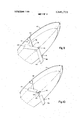
- FIG. 1 is a front view showing flexible fins on a boat resting in the water.
- FIG. 2 shows that an operator can cause the boat of FIG. 1 to tilt to one side.
- FIG. 3 is a side view of FIG. 1.
- FIG. 4 illustrates a hinged fin which can be used in place of the flexible fins of FIG. 1.
- FIG. 5 is a section taken on lines 5-5 of FIG. 4 and viewed in the direction of the arrows.
- FIG. 6 illustrates a webbed fin which can be used in place ofthe flexible fins of FIG. 1.
- FIG. 7 illustrates the flexible fin which is used in FIG. 1.
- the dotted line represents the flexed position.
- FIG. 8 is a section taken on line 8--8 of FIG. 7 and viewed in the direction of the arrows.
- FIG. 9 shows two fins attached to a hinged connector and also to two braces which are attached to the sides of a boat.
- FIG. 10 shows two fins of an alternative design attached to a central connector and to braces as in FIG. 9.
- FIG. 11 shows an operator upon a boat similar to the boat of FIG. 9 except for the addition of means to raise the fins.
- FIG. 12 is a cutaway view of a possible construction for the webbed fins of FIG. 9.
- FIG. 13 is a section of FIG. 12.
- This invention relates to a unique means of propelling a watercraft and could be applied to a boat, canoe,
- the invention is shown embodied in a small boat with two fins.
- FIG. 1 there is illustrated a small boat 10 floating on the water 20.
- the boat has sufficient buoyancy to keep itself, an operator, and all attached fins afloat.
- Rigidly fixed to the underside of the boat are flexible fins l2 and 13.
- FIG. 2 shows that an operator 11 can cause the boat 10 of FIG. 1 to tilt to one side.
- the operator l1 merely repeatedly alternates the side to which the boat is rocked in a side to side motion.
- FIG. 3 shows the side of flexible fin 13 positioned in a resting position.
- FIGS. 4 and 5 illustrate a hinged fin 14, two of which may be used with the boat 10 in place of the two flexible fins of FIG. 1.
- a blade portion 15 is continuous with a rigid leading edge 18 and pivots about a fin pin 16.
- Spring 17 tends to maintain the fin blade portion 15 in a normal position with its two large sides nearly parallel with a centerline along the length of the boat. Both the fin pin and one end of the spring are fixed to the bottom of the boat.
- the normal position is represented by the dotted line configuration in FIGS. 4 and S where the blade is shown at a position directly behind the leading edge.
- the solid line configuration represents a position of the fin when the boat is being rocked from one side to the other. It can be noted that the solid line blade is not directly behind the leading edge 18.
- a force diagram is included to indicate the operating principle: Line A represents resistance to the force rocking the boat; line B represents the forward component, and line C represents the resultant force on the fin.
- FIG. 6 illustrates a webbed fin 24 having a shaft 23 for a leading edge which is rigidly fixed to the bottom of the boat 10. Extending away from the shaft near each end are arms 21 and 25. Stretched between the arms and attached along the length of shaft 23 is an elastic web 22. When the boat is rocked the stretching of the web 22 from its normal'position directly behind the leading edge causes the fin to operate in a similar manner to the hinged fin of FIGS. 4 and 5 and the elastic nature of the web 22 tends to restore it to its original condition behind the leading edge.
- FIGS. 7 and 8 illustrate the flexible fins shown fixed to the bottom of the boat in FIG. 1.
- the leading edge of the fin is a rigid shaft 33 and is fixed to the boat 10 to provide support for the flexible portion 32 which is continuous with and extends outwardly from the shaft 33.
- the solid line configuration represents the fin at rest directly behind the leading edge and the dotted line portion indicates a changed position which would occur as the result of rocking the boat. The elasticity of the material tends to maintain the fin in the solid line configuration.
- a forward thrust is easily created by rocking the boat.
- the fin When a fin is at rest, the fin is positioned to present its narrow dimension in the direction of the intended movement of the craft.
- the leading edge of the fin is comparatively rigid in relation to the hull or body of the craft.
- the fin can pivot at or near the leading edge or flex back of the leading edge, but this pivoting or flexing is resisted by springs which are added (FIGS. 4 and 5) or by the elastic nature of the material of which the fin is made (FIGS 6, 7, and 8).
- the number of fins used, the size of the fins, the placement of the fins and the type of fins used can be varied to give the desired result for a given purpose. For example, for operation of the craft in shallow water hundreds of small fins could be placed on the underside of a craft instead of a few large fins.
- a fin 44 similar to webbed fin 24 of FIG. 6 may be constructed as shown in FIGS. 12 and 13.
- Wood base 60 holds one end of a spring steel frame 67 which is held under tension along its open side by rubber band 64.
- rubber band 64 Surrounded by the rubber band is wood support 66, and attached along the wood support 66 is a piece of solid rubber 65 as shown in FIGS. 12 and 13. The rest of the enclosed area of frame 67 is occupied by foam rubber 61. Rubber covering 63 encloses the entire fin.
- a webbed fin such as those shown in FIGS. 6 and 12 is particularly suitable for propelling a boat (such as forward in the manner described.
- webb 22 of fin 24 forms a pocket or a concave curve on the pressure side and a convex curve on the lee side.
- This action of the webb allows the leading edge to enter the water at a very low angle and to initiate a smooth flow of water over both surfaces.
- the curve of the webb then maintains an effective thrust against the water across the full width of the fin.
- the webb forms an efficient curved fan blade" or air foil shape in either direction as the boat is rocked from side' to side.
- the same curved shape is formed on the inside of arms 21 and so that water in those areas is directed inward and the loss due to water escaping around the ends is largely eliminated.
- FIG. 6 and FIG; 12 An additional benefit of a webbed fin as shown in FIG. 6 and FIG; 12 is that the torsion of arm 21 about the axis of shaft 23 may exceed that of arm 25. Since the outer extremity of the fin travels through the water at a greater angle than the portion near a boat, such as 10, the twisting effect allows the fin to adjust to its most efficient angle along its entire length.
- the webbed fins of FIGS. 6 or 12 may be attached to the boat 10 as shown in FIG. 2 or in alternative manners.
- Braces 40 and 41 are shown attached to the sides of boat 10 in FIG. 9. Braces 40 and 41 are pivotally attached to fins 44 and at pivot points 38 and 39. Fins 44 and 45 are attached at their ends to a connector 42 on the centerline of the bottom of the boat 10.
- braces 40 and 41 are as wide as fins 44 and 45 at their widest portion 36.
- the braces 40 and 41 each have a narrow portion 37 as shown on brace 40 in FIG. 9. This 5 allows proper water flow past the brace as the boat rocks.
- the braces 40 and 41 restrict lateral movement of the fins 44 and 45 and hence of the boat 10, but through the pivotal attachment 38 and 39, the braces allow the fins 44 and 45 to twist and develop maximum forward forces when the boat 10 is rocked.
- FIG. 10 shows braces 40 and 41 attached to boat 10 and used in conjunction with a different fin arrangement.
- Spring steel fin shafts 48 and 49 attach to connector 43 and fins 46 and 47.
- Braces 40 and 41 are attached pivotally to fins 46 and 47 as in FIG. 9.
- fins 46 and 47 may be flexible or they may be rigid.
- the sideward stability of the boat and braces of FIG. 9 also obtains in the arrangement in FIG. 10.
- FIG. 11 illustrates braces 50 and 51 which are permanently attached to fins 44 and 45 but removably attached to boat 10.
- the braces 50 and 51 may be raised as shown in FIG. 11, which raises fins 44 and 45, allowing the boat 10 to be easily moved ashore.
- Connector 42 is a hinge which allows the pivoting of the fins 44 and 45 when they are raised.
- Directional guidance can be provided with a rudder or can alternatively be provided by operating the craft in a heeled attitude.
- Guiding fins can be added at each side of the boat to aid in the turning of the boat or movable guiding fins could be added so that additional thrust could easily be added to either side of the craft.
- the fin or fins used could be retractable into a cavity in the buoyant portion in 21mmner similar to the design of retractable centerboards in sailboats.
- a fin could either retract by moving straight up or by pivoting in a jack-knife fashion, thus allowing the craft to coast onto a beach.
- Numerous other embodiments could be made by a person of ordinary skill which would still allow efficient propulsion by rocking the boat, now that I have described my invention.
- a craft propelled by an operator by rocking from 1 side to side which comprises:
Landscapes
- Chemical & Material Sciences (AREA)
- Engineering & Computer Science (AREA)
- Combustion & Propulsion (AREA)
- Mechanical Engineering (AREA)
- Ocean & Marine Engineering (AREA)
- Toys (AREA)
Abstract
Flexible, webbed or pivoted fins project from a watercraft and provide thrust to propel the craft when the craft is caused to rock from side to side either by the rider or by wave action. The fins may be pivoted having the axis of rotation at their leading edge and having a spring tending to maintain the position of the fin, or the fins may be of a webbed construction.
Description
United States Patent 11 1 .1 ackman 1 Nov. 5, 1974 1 BOAT PROPULSION MEANS [76] Inventor: Richard L. Jackman, 2509 S. Main St., New Castle, Ind. 47362 [22] Filed: June 11, 1973 21 Appl. No.: 364,802
Related U.S. Application Data [63] Continuation-in-part of Ser. No. 320,109, Jan. 2, 1973, abandoned, which is a continuation of Ser. No. 91076, Nov. 19, 1970, abandoned.
52 U.S. C1. 115/28 R, 416/81 [51] Int. (31 B63h l/32 [58] Field of Search 115/28 R, 4, 29, 30; 416/81, 66, 132; 244/123; 114/152 [56] 7 References Cited UNITED STATES PATENTS 798,845 9/1905 Ulrich 1. 416/132 1,204,937 11/1916 1,661,921 3/1928 2,173,415 9/1939 Hill 416/81 2,996,034 8/1931 Jonsson 115/28 R 3,078,482 2/1963 Crowder 115/28 R 3,453,981 7/1969 Gause 115/28 R 3,519,228 7/1970 Windeckcr 244/123 3,640,240 2/1972 Stein 115/28 R 3,773,011 11/1973 Gronier 115/28 R FOREIGN PATENTS OR APPLICATIONS 541,775 12/1941 Great Britain 115/4 Primary Examiner-Trygve M. Blix Assistant Examiner-Galen Bareioot Zft brney, Agent, or Firm Woodard, Weikart, Emhardt & Naughton [57] ABSTRACT Flexible, webbed or pivoted fins project from a watercraft and provide thrust to propel the craft when the craft is caused to rock from side to side either by the rider or by wave action. The fins may be pivoted having the axis of rotation at their leading edge and having a spring tending to maintain the position of the fin, or the fins may be of a webbed construction.
1 Claim, 13 Drawing Figures PATENTED I!" 5 I97 sum 10; a
INVENTOR 16mm L L/ICAMAA/ BY a/m/m 1121mm f ATTORNEYS BOAT PROPULSION MEANS CROSS-REFERENCE TO RELATED APPLICATIONS BACKGROUND OF THE INVENTION 1. Field of the Invention This invention relates to a device and technique for marine propulsion.
2. Description of the Prior Art In the prior art there are numerous devices for marine propulsion. Rigid fins or keels are commonly used to prevent the rocking back and forth of a watercraft which incorporates another system of propulsion. Devices have been described in US. patents which claim to have a propelling effect due to the motion of the occupant of the device, but these devices are not operated by rocking the boat from side to side and they are designed for operation through the use of the operators hands.
Devices which propel a boat as the result of side to side rocking of the boat are known. A rigid blade, or several rigid blades, is attached to the underside of the boat in these devices. Sometimes a solid blade of resilient material is used.
SUMMARY OF THE INVENTION This invention relates to a watercraft having one or more fins, which is propelled by an operator by rocking the craft from side to side. The fins have a rigid leading edge. a movable blade portion and means tending to maintain the blade portion behind the leading edge. A device embodying this invention has the advantage of being able to be propelled without the use of the operator's hands. In the flexible fin embodiment the entire craft and fins are very reliable because there are no hinge points, gears, springs, or other similar devices. The hinged fin and webbed fin are also unlikely to fail, because of their simplicity.
BRIEF DESCRIPTION OF THE DRAWINGS FIG. 1 is a front view showing flexible fins on a boat resting in the water.
FIG. 2 shows that an operator can cause the boat of FIG. 1 to tilt to one side.
FIG. 3 is a side view of FIG. 1.
FIG. 4 illustrates a hinged fin which can be used in place of the flexible fins of FIG. 1.
FIG. 5 is a section taken on lines 5-5 of FIG. 4 and viewed in the direction of the arrows.
FIG. 6 illustrates a webbed fin which can be used in place ofthe flexible fins of FIG. 1.
FIG. 7 illustrates the flexible fin which is used in FIG. 1. The dotted line represents the flexed position.
FIG. 8 is a section taken on line 8--8 of FIG. 7 and viewed in the direction of the arrows.
FIG. 9 shows two fins attached to a hinged connector and also to two braces which are attached to the sides of a boat.
FIG. 10 shows two fins of an alternative design attached to a central connector and to braces as in FIG. 9.
FIG. 11 shows an operator upon a boat similar to the boat of FIG. 9 except for the addition of means to raise the fins.
FIG. 12 is a cutaway view of a possible construction for the webbed fins of FIG. 9.
FIG. 13 is a section of FIG. 12.
DESCRIPTION OF THE PREFERRED EMBODIMENT This invention relates to a unique means of propelling a watercraft and could be applied to a boat, canoe,
surfboard, toy boat or any similar craft. For purposes of illustration, the invention is shown embodied in a small boat with two fins.
Referring more particularly to FIG. 1, there is illustrated a small boat 10 floating on the water 20. The boat has sufficient buoyancy to keep itself, an operator, and all attached fins afloat. Rigidly fixed to the underside of the boat are flexible fins l2 and 13. FIG. 2 shows that an operator 11 can cause the boat 10 of FIG. 1 to tilt to one side. To make the boat go forward, the operator l1 merely repeatedly alternates the side to which the boat is rocked in a side to side motion. As a side view of the boat 10 of FIG. 1, FIG. 3 shows the side of flexible fin 13 positioned in a resting position.
FIGS. 4 and 5 illustrate a hinged fin 14, two of which may be used with the boat 10 in place of the two flexible fins of FIG. 1. A blade portion 15 is continuous with a rigid leading edge 18 and pivots about a fin pin 16. Spring 17 tends to maintain the fin blade portion 15 in a normal position with its two large sides nearly parallel with a centerline along the length of the boat. Both the fin pin and one end of the spring are fixed to the bottom of the boat. The normal position is represented by the dotted line configuration in FIGS. 4 and S where the blade is shown at a position directly behind the leading edge. The solid line configuration represents a position of the fin when the boat is being rocked from one side to the other. It can be noted that the solid line blade is not directly behind the leading edge 18. A force diagram is included to indicate the operating principle: Line A represents resistance to the force rocking the boat; line B represents the forward component, and line C represents the resultant force on the fin.
FIG. 6 illustrates a webbed fin 24 having a shaft 23 for a leading edge which is rigidly fixed to the bottom of the boat 10. Extending away from the shaft near each end are arms 21 and 25. Stretched between the arms and attached along the length of shaft 23 is an elastic web 22. When the boat is rocked the stretching of the web 22 from its normal'position directly behind the leading edge causes the fin to operate in a similar manner to the hinged fin of FIGS. 4 and 5 and the elastic nature of the web 22 tends to restore it to its original condition behind the leading edge. FIGS. 7 and 8 illustrate the flexible fins shown fixed to the bottom of the boat in FIG. 1. The leading edge of the fin is a rigid shaft 33 and is fixed to the boat 10 to provide support for the flexible portion 32 which is continuous with and extends outwardly from the shaft 33. The solid line configuration represents the fin at rest directly behind the leading edge and the dotted line portion indicates a changed position which would occur as the result of rocking the boat. The elasticity of the material tends to maintain the fin in the solid line configuration.
In operation, a forward thrust is easily created by rocking the boat. When a fin is at rest, the fin is positioned to present its narrow dimension in the direction of the intended movement of the craft. The leading edge of the fin is comparatively rigid in relation to the hull or body of the craft. The fin can pivot at or near the leading edge or flex back of the leading edge, but this pivoting or flexing is resisted by springs which are added (FIGS. 4 and 5) or by the elastic nature of the material of which the fin is made (FIGS 6, 7, and 8). When an action of the craft causes a fin to move broadside through the water, a force is created on the side of the fin and the fin deflects. This deflection of the fins causes water to be forced to the rear and the boat to move forward.
The number of fins used, the size of the fins, the placement of the fins and the type of fins used can be varied to give the desired result for a given purpose. For example, for operation of the craft in shallow water hundreds of small fins could be placed on the underside of a craft instead of a few large fins.
As another example, a fin 44 similar to webbed fin 24 of FIG. 6 may be constructed as shown in FIGS. 12 and 13. Wood base 60 holds one end of a spring steel frame 67 which is held under tension along its open side by rubber band 64. Surrounded by the rubber band is wood support 66, and attached along the wood support 66 is a piece of solid rubber 65 as shown in FIGS. 12 and 13. The rest of the enclosed area of frame 67 is occupied by foam rubber 61. Rubber covering 63 encloses the entire fin.
A webbed fin, such as those shown in FIGS. 6 and 12 is particularly suitable for propelling a boat (such as forward in the manner described. When the boat is rocked, webb 22 of fin 24 forms a pocket or a concave curve on the pressure side and a convex curve on the lee side. This action of the webb allows the leading edge to enter the water at a very low angle and to initiate a smooth flow of water over both surfaces. The curve of the webb then maintains an effective thrust against the water across the full width of the fin. In other words the webb forms an efficient curved fan blade" or air foil shape in either direction as the boat is rocked from side' to side. The same curved shape is formed on the inside of arms 21 and so that water in those areas is directed inward and the loss due to water escaping around the ends is largely eliminated.
An additional benefit of a webbed fin as shown in FIG. 6 and FIG; 12 is that the torsion of arm 21 about the axis of shaft 23 may exceed that of arm 25. Since the outer extremity of the fin travels through the water at a greater angle than the portion near a boat, such as 10, the twisting effect allows the fin to adjust to its most efficient angle along its entire length.
The webbed fins of FIGS. 6 or 12 may be attached to the boat 10 as shown in FIG. 2 or in alternative manners.
braces 40 and 41 are as wide as fins 44 and 45 at their widest portion 36. The braces 40 and 41 each have a narrow portion 37 as shown on brace 40 in FIG. 9. This 5 allows proper water flow past the brace as the boat rocks. The braces 40 and 41 restrict lateral movement of the fins 44 and 45 and hence of the boat 10, but through the pivotal attachment 38 and 39, the braces allow the fins 44 and 45 to twist and develop maximum forward forces when the boat 10 is rocked.
FIG. 10 shows braces 40 and 41 attached to boat 10 and used in conjunction with a different fin arrangement. Spring steel fin shafts 48 and 49 attach to connector 43 and fins 46 and 47. Braces 40 and 41 are attached pivotally to fins 46 and 47 as in FIG. 9. In this configuration, fins 46 and 47 may be flexible or they may be rigid. The sideward stability of the boat and braces of FIG. 9 also obtains in the arrangement in FIG. 10.
FIG. 11 illustrates braces 50 and 51 which are permanently attached to fins 44 and 45 but removably attached to boat 10. The braces 50 and 51 may be raised as shown in FIG. 11, which raises fins 44 and 45, allowing the boat 10 to be easily moved ashore. When boat 10 is not ashore and braces 50 and 51 are lowered, they are locked into position with a conventional latch (not shown) so that the rocking of boat 10 imparts motions to the fins 44' and 45. Connector 42 is a hinge which allows the pivoting of the fins 44 and 45 when they are raised.
Directional guidance can be provided with a rudder or can alternatively be provided by operating the craft in a heeled attitude. Guiding fins can be added at each side of the boat to aid in the turning of the boat or movable guiding fins could be added so that additional thrust could easily be added to either side of the craft.
As another example, the fin or fins used could be retractable into a cavity in the buoyant portion in 21mmner similar to the design of retractable centerboards in sailboats. A fin could either retract by moving straight up or by pivoting in a jack-knife fashion, thus allowing the craft to coast onto a beach. Numerous other embodiments could be made by a person of ordinary skill which would still allow efficient propulsion by rocking the boat, now that I have described my invention.
The invention claimed is:
1. A craft propelled by an operator by rocking from 1 side to side which comprises:
5. an elastic band stretched between said arms along the trailing edge of said fin.
Claims (5)
1. A craft propelled by an operator by rocking from side to side which comprises: a. a buoyant portion being of sufficient buoyancy to keep itself and an operator afloat and b. a fin fixed to the buoyant portion and having 1. a rigid leading edge, 2. arms extending away from said leading edge near each of its ends, 3. webbing material attached to said arms and generally between them, 4. a support member positioned along the trailing edge of said fin and generally between said arms and 5. an elastic band stretched between said arms along the trailing edge of said fin.
2. arms extending away from said leading edge near each of its ends,
3. webbing material attached to said arms and generally between them,
4. a support member positioned along the trailing edge of said fin and generally between said arms and
5. an elastic band stretched between said arms along the trailing edge of said fin.
Priority Applications (1)
| Application Number | Priority Date | Filing Date | Title |
|---|---|---|---|
| US00364802A US3845733A (en) | 1973-01-02 | 1973-06-11 | Boat propulsion means |
Applications Claiming Priority (2)
| Application Number | Priority Date | Filing Date | Title |
|---|---|---|---|
| US32010973A | 1973-01-02 | 1973-01-02 | |
| US00364802A US3845733A (en) | 1973-01-02 | 1973-06-11 | Boat propulsion means |
Publications (1)
| Publication Number | Publication Date |
|---|---|
| US3845733A true US3845733A (en) | 1974-11-05 |
Family
ID=26982309
Family Applications (1)
| Application Number | Title | Priority Date | Filing Date |
|---|---|---|---|
| US00364802A Expired - Lifetime US3845733A (en) | 1973-01-02 | 1973-06-11 | Boat propulsion means |
Country Status (1)
| Country | Link |
|---|---|
| US (1) | US3845733A (en) |
Cited By (24)
| Publication number | Priority date | Publication date | Assignee | Title |
|---|---|---|---|---|
| FR2400925A2 (en) * | 1977-08-23 | 1979-03-23 | Coutrot Robert | Floating water toy for child - has side and tail fins on board which is rocked laterally to submerge fins and provide forward movement |
| US4214547A (en) * | 1978-07-31 | 1980-07-29 | Hetland Philip R | Rider propelled boat |
| FR2706849A1 (en) * | 1993-06-24 | 1994-12-30 | Proverbio Rodolphe | |
| US20070032144A1 (en) * | 2005-08-08 | 2007-02-08 | Ketterman Gregory S | Fin for oscillating foil propulsion system |
| US20070173141A1 (en) * | 2006-01-20 | 2007-07-26 | Hine Roger G | Wave power |
| WO2007087197A2 (en) | 2006-01-20 | 2007-08-02 | Liquid Robotics Incorporated | Wave power |
| WO2008109002A2 (en) | 2007-03-02 | 2008-09-12 | Liquid Robotics Incorporated | Wave power |
| WO2012126009A2 (en) | 2011-03-17 | 2012-09-20 | Liquid Robotics, Inc. | Wave-powered devices configured for nesting |
| WO2012126012A2 (en) | 2011-03-17 | 2012-09-20 | Liquid Robotics, Inc. | Wave-powered device with one or more tethers having one or more rigid sections |
| US8717844B2 (en) | 2010-02-23 | 2014-05-06 | Westerngeco L.L.C. | Seismic data acquisition using self-propelled underwater vehicles |
| US8808041B2 (en) | 2011-06-28 | 2014-08-19 | Liquid Robotics, Inc. | Watercraft that harvest both locomotive thrust and electrical power from wave motion |
| US8825241B2 (en) | 2011-03-17 | 2014-09-02 | Liquid Robotics, Inc. | Autonomous wave-powered substance distribution vessels for fertilizing plankton, feeding fish, and sequestering carbon from the atmosphere |
| WO2014145601A2 (en) | 2013-03-15 | 2014-09-18 | Liquid Robotics, Inc. | Adaptable modular power system (amps) and dedicated connector; modular payload boxes and autonomous water vehicle configured to accept same |
| US8944866B2 (en) | 2011-09-15 | 2015-02-03 | Liquid Robotics, Inc. | Wave-powered endurance extension module for unmanned underwater vehicles |
| WO2016141394A1 (en) * | 2015-03-09 | 2016-09-15 | Hermann Riegerbauer | Drive device for a surfboard |
| WO2016151318A1 (en) * | 2015-03-26 | 2016-09-29 | Pecfins Limited | Fin assembly for a water board and user propelled water board apparatus |
| CN106005332A (en) * | 2016-06-02 | 2016-10-12 | 上海交通大学 | Oscillatory type web-shaped propelling device |
| US9524646B2 (en) | 2011-03-17 | 2016-12-20 | Liquid Robotics, Inc. | Navigation of a fleet of autonomous vessels in current and wind |
| US9533740B2 (en) | 2013-03-15 | 2017-01-03 | Liquid Robotics, Inc. | Adaptable modular power system (AMPS) |
| US9738362B2 (en) | 2015-07-22 | 2017-08-22 | Hobie Cat Company | Flow fin |
| US10207783B1 (en) | 2018-04-04 | 2019-02-19 | Marjaneh Marjan | Paddleboard kit |
| AT517517A3 (en) * | 2015-07-20 | 2019-08-15 | Riegerbauer Hermann | Drive device for a surfboard |
| US10647396B2 (en) | 2018-04-04 | 2020-05-12 | Marjaneh Marjan | Paddleboard kit |
| US20210171173A1 (en) * | 2017-11-08 | 2021-06-10 | James F. Kramer | Personal watercraft |
Citations (11)
| Publication number | Priority date | Publication date | Assignee | Title |
|---|---|---|---|---|
| US798845A (en) * | 1905-06-05 | 1905-09-05 | Otto Ulrich | Wind-wheel. |
| US1204937A (en) * | 1915-12-02 | 1916-11-14 | George G Frost | Mechanism for propelling and steadying boats. |
| US1661921A (en) * | 1926-07-07 | 1928-03-06 | John Alexander Fisher | Blade for propellers, ventilating fans, and the like |
| US2173415A (en) * | 1938-03-31 | 1939-09-19 | Roland C Hill | Propelling mechanism |
| GB541775A (en) * | 1938-08-08 | 1941-12-11 | Brev Moineau S A R L Soc D Exp | Improvements in devices for the propulsion of watercraft |
| US2996034A (en) * | 1958-04-17 | 1961-08-15 | Jonsson Karl-Erik Arnold | Device for propelling and stabilizing of boats |
| US3078482A (en) * | 1959-05-11 | 1963-02-26 | Wyly K Crowder | Swimming accessory |
| US3453981A (en) * | 1967-04-24 | 1969-07-08 | Joseph A Gause | Water-borne vessel comprising propulsion system incorporating flexible fin propulsion members |
| US3519228A (en) * | 1967-09-29 | 1970-07-07 | Dow Chemical Co | Airfoil structure |
| US3640240A (en) * | 1969-03-07 | 1972-02-08 | Erich Stein | Fin-propelled watercraft |
| US3773011A (en) * | 1971-03-08 | 1973-11-20 | J Gronier | Propulsion fin for a floating body |
-
1973
- 1973-06-11 US US00364802A patent/US3845733A/en not_active Expired - Lifetime
Patent Citations (11)
| Publication number | Priority date | Publication date | Assignee | Title |
|---|---|---|---|---|
| US798845A (en) * | 1905-06-05 | 1905-09-05 | Otto Ulrich | Wind-wheel. |
| US1204937A (en) * | 1915-12-02 | 1916-11-14 | George G Frost | Mechanism for propelling and steadying boats. |
| US1661921A (en) * | 1926-07-07 | 1928-03-06 | John Alexander Fisher | Blade for propellers, ventilating fans, and the like |
| US2173415A (en) * | 1938-03-31 | 1939-09-19 | Roland C Hill | Propelling mechanism |
| GB541775A (en) * | 1938-08-08 | 1941-12-11 | Brev Moineau S A R L Soc D Exp | Improvements in devices for the propulsion of watercraft |
| US2996034A (en) * | 1958-04-17 | 1961-08-15 | Jonsson Karl-Erik Arnold | Device for propelling and stabilizing of boats |
| US3078482A (en) * | 1959-05-11 | 1963-02-26 | Wyly K Crowder | Swimming accessory |
| US3453981A (en) * | 1967-04-24 | 1969-07-08 | Joseph A Gause | Water-borne vessel comprising propulsion system incorporating flexible fin propulsion members |
| US3519228A (en) * | 1967-09-29 | 1970-07-07 | Dow Chemical Co | Airfoil structure |
| US3640240A (en) * | 1969-03-07 | 1972-02-08 | Erich Stein | Fin-propelled watercraft |
| US3773011A (en) * | 1971-03-08 | 1973-11-20 | J Gronier | Propulsion fin for a floating body |
Cited By (62)
| Publication number | Priority date | Publication date | Assignee | Title |
|---|---|---|---|---|
| FR2400925A2 (en) * | 1977-08-23 | 1979-03-23 | Coutrot Robert | Floating water toy for child - has side and tail fins on board which is rocked laterally to submerge fins and provide forward movement |
| US4214547A (en) * | 1978-07-31 | 1980-07-29 | Hetland Philip R | Rider propelled boat |
| FR2706849A1 (en) * | 1993-06-24 | 1994-12-30 | Proverbio Rodolphe | |
| WO1995000389A1 (en) * | 1993-06-24 | 1995-01-05 | Rodolphe Proverbio | Muscle-powered watercraft |
| US7637791B2 (en) * | 2005-08-08 | 2009-12-29 | Hobie Cat Company | Fin for oscillating foil propulsion system |
| US20070032144A1 (en) * | 2005-08-08 | 2007-02-08 | Ketterman Gregory S | Fin for oscillating foil propulsion system |
| US9731802B2 (en) * | 2005-08-08 | 2017-08-15 | Hobie Cat Company | Fin for oscillating foil propulsion system |
| US9540086B2 (en) | 2005-08-08 | 2017-01-10 | Hobie Cat Company | Fin for oscillating foil propulsion system |
| US20160052610A1 (en) * | 2005-08-08 | 2016-02-25 | Hobie Cat Company, A Missouri Corporation | Fin For Oscillating Foil Propulsion System |
| US10150545B2 (en) | 2006-01-20 | 2018-12-11 | Liquid Robotics, Inc. | Wave power |
| EP2821339A2 (en) | 2006-01-20 | 2015-01-07 | Liquid Robotics, Inc. | Wave power |
| US20070173141A1 (en) * | 2006-01-20 | 2007-07-26 | Hine Roger G | Wave power |
| US7641524B2 (en) | 2006-01-20 | 2010-01-05 | Liquid Robotics Inc. | Wave power vehicle tethers |
| US9623945B2 (en) | 2006-01-20 | 2017-04-18 | Liquid Robotics Inc. | Wave power |
| WO2007087197A2 (en) | 2006-01-20 | 2007-08-02 | Liquid Robotics Incorporated | Wave power |
| US7371136B2 (en) | 2006-01-20 | 2008-05-13 | Liquid Robotics Inc. | Wave power |
| US8287323B2 (en) | 2006-01-20 | 2012-10-16 | Liquid Robotics, Inc | Wave power components |
| US8376790B2 (en) | 2006-01-20 | 2013-02-19 | Liquid Robotics Inc. | Wave power |
| US20080188150A1 (en) * | 2006-01-20 | 2008-08-07 | Hine Roger G | Wave power components |
| US9051037B2 (en) | 2006-01-20 | 2015-06-09 | Liquid Robotics, Inc. | Wave power |
| US20080299843A1 (en) * | 2006-01-20 | 2008-12-04 | Hine Roger G | Wave power vehicle tethers |
| US9151267B2 (en) | 2006-05-18 | 2015-10-06 | Liquid Robotics, Inc. | Wave-powered devices configured for nesting |
| US10041466B2 (en) | 2006-05-18 | 2018-08-07 | Liquid Robotics, Inc. | Wave-powered devices configured for nesting |
| US10315746B2 (en) | 2007-03-02 | 2019-06-11 | Liquid Robotics, Inc. | Cable for connecting a float to a swimmer in a wave powered vehicle |
| US20100190394A1 (en) * | 2007-03-02 | 2010-07-29 | Hine Roger G | Wave power |
| EP3514050A1 (en) | 2007-03-02 | 2019-07-24 | Liquid Robotics, Inc. | Wave power |
| WO2008109002A2 (en) | 2007-03-02 | 2008-09-12 | Liquid Robotics Incorporated | Wave power |
| US11027810B2 (en) | 2007-03-02 | 2021-06-08 | Liquid Robotics, Inc. | Float for connection to a swimmer in a wave powered vehicle |
| US8668534B2 (en) | 2007-03-02 | 2014-03-11 | Liquid Robotics, Inc | Wave power |
| US11685494B2 (en) | 2007-03-02 | 2023-06-27 | Liquid Robotics, Inc. | Method and apparatus for untwisting a tether of a water powered vehicle |
| US9789944B2 (en) | 2007-03-02 | 2017-10-17 | Liquid Robotics, Inc. | Cable for connecting a float to a swimmer in a wave powered vehicle |
| US9575198B2 (en) | 2010-02-23 | 2017-02-21 | Westerngeco L.L.C. | Seismic data acquisition using self-propelled underwater vehicles |
| US8717844B2 (en) | 2010-02-23 | 2014-05-06 | Westerngeco L.L.C. | Seismic data acquisition using self-propelled underwater vehicles |
| US8825241B2 (en) | 2011-03-17 | 2014-09-02 | Liquid Robotics, Inc. | Autonomous wave-powered substance distribution vessels for fertilizing plankton, feeding fish, and sequestering carbon from the atmosphere |
| US9524646B2 (en) | 2011-03-17 | 2016-12-20 | Liquid Robotics, Inc. | Navigation of a fleet of autonomous vessels in current and wind |
| EP3267275A1 (en) | 2011-03-17 | 2018-01-10 | Liquid Robotics, Inc. | Wave-powered devices configured for nesting |
| WO2012126009A2 (en) | 2011-03-17 | 2012-09-20 | Liquid Robotics, Inc. | Wave-powered devices configured for nesting |
| US8764498B2 (en) | 2011-03-17 | 2014-07-01 | Liquid Robotics, Inc. | Wave-powered device with one or more tethers having one or more rigid sections |
| WO2012126012A2 (en) | 2011-03-17 | 2012-09-20 | Liquid Robotics, Inc. | Wave-powered device with one or more tethers having one or more rigid sections |
| US9802681B1 (en) | 2011-03-17 | 2017-10-31 | Liquid Robotics, Inc. | Autonomous wave-powered vessels and fleets for managing fish stock |
| US10150546B2 (en) | 2011-06-28 | 2018-12-11 | Liquid Robotics, Inc. | Watercraft equipped with a hybrid wave-powered electricity generating and propulsion system |
| US10549832B2 (en) | 2011-06-28 | 2020-02-04 | Liquid Robotics, Inc. | Watercraft equipped with a hybrid wave-powered electricity generating and propulsion system |
| US9688373B2 (en) | 2011-06-28 | 2017-06-27 | Liquid Robotics, Inc. | Watercraft equipped with a wave-powered electricity generating system and a deployable tow buoy |
| US8808041B2 (en) | 2011-06-28 | 2014-08-19 | Liquid Robotics, Inc. | Watercraft that harvest both locomotive thrust and electrical power from wave motion |
| US11192621B2 (en) | 2011-06-28 | 2021-12-07 | Liquid Robotics, Inc. | Watercraft and electricity generator system for harvesting electrical power for wave motion |
| US9353725B2 (en) | 2011-06-28 | 2016-05-31 | Liquid Robotics, Inc. | Watercraft and electricity generator system for harvesting electrical power from wave motion |
| US8944866B2 (en) | 2011-09-15 | 2015-02-03 | Liquid Robotics, Inc. | Wave-powered endurance extension module for unmanned underwater vehicles |
| US9533740B2 (en) | 2013-03-15 | 2017-01-03 | Liquid Robotics, Inc. | Adaptable modular power system (AMPS) |
| US10005535B2 (en) | 2013-03-15 | 2018-06-26 | Liquid Robotics, Inc. | Adaptable modular power system (AMPS) and dedicated connector; modular payload boxes and autonomous water vehicle configured to accept same |
| WO2014145601A2 (en) | 2013-03-15 | 2014-09-18 | Liquid Robotics, Inc. | Adaptable modular power system (amps) and dedicated connector; modular payload boxes and autonomous water vehicle configured to accept same |
| US10913523B2 (en) | 2013-03-15 | 2021-02-09 | Liquid Robotics, Inc. | Adaptable modular power system (AMPS) and dedicated connector; modular payload boxes and autonomous water vehicle configured to accept same |
| WO2016141394A1 (en) * | 2015-03-09 | 2016-09-15 | Hermann Riegerbauer | Drive device for a surfboard |
| WO2016151318A1 (en) * | 2015-03-26 | 2016-09-29 | Pecfins Limited | Fin assembly for a water board and user propelled water board apparatus |
| AT517517B1 (en) * | 2015-07-20 | 2019-11-15 | Riegerbauer Hermann | Drive device for a surfboard |
| AT517517A3 (en) * | 2015-07-20 | 2019-08-15 | Riegerbauer Hermann | Drive device for a surfboard |
| US9738362B2 (en) | 2015-07-22 | 2017-08-22 | Hobie Cat Company | Flow fin |
| CN106005332A (en) * | 2016-06-02 | 2016-10-12 | 上海交通大学 | Oscillatory type web-shaped propelling device |
| US20210171173A1 (en) * | 2017-11-08 | 2021-06-10 | James F. Kramer | Personal watercraft |
| US11926401B2 (en) * | 2017-11-08 | 2024-03-12 | James F. Kramer | Personal watercraft |
| US10647396B2 (en) | 2018-04-04 | 2020-05-12 | Marjaneh Marjan | Paddleboard kit |
| US10683072B2 (en) | 2018-04-04 | 2020-06-16 | Marjaneh Marjan | Paddleboard kit |
| US10207783B1 (en) | 2018-04-04 | 2019-02-19 | Marjaneh Marjan | Paddleboard kit |
Similar Documents
| Publication | Publication Date | Title |
|---|---|---|
| US3845733A (en) | Boat propulsion means | |
| US4129912A (en) | Aquatic device | |
| US3453981A (en) | Water-borne vessel comprising propulsion system incorporating flexible fin propulsion members | |
| US3665535A (en) | Swim fin | |
| US3677216A (en) | Rowing device | |
| US4936802A (en) | Swinging and propelling ship | |
| US4063320A (en) | Inflatable boat | |
| US6000355A (en) | Stabilized watercraft | |
| US3500784A (en) | Surface craft | |
| US2991746A (en) | Marine speed craft | |
| US5643020A (en) | Personal watercraft | |
| JP5135685B2 (en) | Swing type horizontal fin propulsion manpowered ship | |
| KR880002480B1 (en) | Improvements in and relating to sail arrangements for boats and the like | |
| US4046097A (en) | Collar for redirecting propeller energy | |
| US3605676A (en) | Motorless water-borne vehicles | |
| US3834343A (en) | Articulated sculling oar | |
| US3722015A (en) | Water board | |
| US5603277A (en) | Tack aback sailboat | |
| US4464126A (en) | Finboard exercising apparatus | |
| US4698033A (en) | Recreational watercraft | |
| US5682831A (en) | Water surface glide sailboat utilizing wind power propelling | |
| US9889917B1 (en) | Curve and tilt passive cambering keel and steering fin mastless wingsail | |
| KR102168130B1 (en) | Propellant body using the law of action and reaction | |
| JP3775606B2 (en) | Wireless control toy surfers | |
| US3982495A (en) | Bicycle powered boat |