US3662861A - Elevator control dispensing with traveling cables - Google Patents
Elevator control dispensing with traveling cables Download PDFInfo
- Publication number
- US3662861A US3662861A US850046A US3662861DA US3662861A US 3662861 A US3662861 A US 3662861A US 850046 A US850046 A US 850046A US 3662861D A US3662861D A US 3662861DA US 3662861 A US3662861 A US 3662861A
- Authority
- US
- United States
- Prior art keywords
- car
- command
- oscillations
- cable
- receiver
- Prior art date
- Legal status (The legal status is an assumption and is not a legal conclusion. Google has not performed a legal analysis and makes no representation as to the accuracy of the status listed.)
- Expired - Lifetime
Links
Images


Classifications
-
- H—ELECTRICITY
- H04—ELECTRIC COMMUNICATION TECHNIQUE
- H04B—TRANSMISSION
- H04B3/00—Line transmission systems
- H04B3/60—Systems for communication between relatively movable stations, e.g. for communication with lift
Definitions
- the transmitter-receiver system operates at low frequencies (between about 300 to 1,200 cycles/sec.) to avoid [56] Rem-"Ices Cited electromagnetic radiation and its signals are so coded as to in- U D STATES PATENTS sure unambiguous command signals immune to electrical noise, and to provide certain fail-safe features. 2,930,955 3/1960 Bourget et al.... ....3l8/460 X 3,203,506 8/1965 Cummins l 87/29 11 Claims, 7 Drawing Figures E E J 7%: wow
- the industry has suffered the problems of the traveling cable for many years.
- the problems arise from the very nature of the traveling cable. It interferes with other structures in the elevator shaft; it swings about erratically; and it is therefore frequently damaged causing expensive time-consuming repairs and time-wasting immobilization of the elevator system.
- Many efforts have been made to solve the problems, particularly by expensive complicated restraining guides for the traveling cable as it moves up and down.
- the problems of the traveling cable are particularly severe in elevators of the type used in the building construction industry.
- elevators in-the building construction industry are usually in simple skeletal extendible shafts open to the air. Wind and dirt, therefore, aggravate the wear and tear on the traveling cable, particularly wind which causes the cable to swing erratically and therefore to collide with other structures which will cause it to be damaged or even break.
- the invention eliminates the problems of the traveling cable by eliminating-the traveling cable.
- the invention comprises a system in which Up" and "Down command signals may be sent from the elevator car to the hoist motor at the bottom or top of the shaft without interconnecting conducting cables such as the traveling cable.
- the signals are sent by magnetically coupling through magnetic flux, a transmitter in the car and a receiver at the motor to a cable in the shaft or to a fixed structural member of the elevator shaft either of which acts as the secondary of. a transformer coupling the receiver to the transmitter entirely through the medium of magnetic flux, and totally without any conductive paths.
- the receiver controls the hoist motor.
- Means are also provided for coding the signals between transmitter and receiver in such a way as to insure unambiguous command signals immune to electrical interference (electrical noise). This means includes certain fail-safe features.
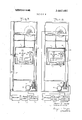
- FIG. I is an elevator system in accordance with the invention in which the command signals from the elevator car are coupled magnetically to a steel cable in the elevator shaft and from there to a receiver which controls the hoist motor.
- FIG. 2 is a detail of the transformer construction of FIG. 1.
- FIG. 3 is similar to FIG. 1, but differs in that the coupling is to the metal guide rail of the shaft.
- FIG. 4 is a detail of the transformer construction of FIG. 3.
- FIG. 5 is similar to the previous FIGS. 1 and 3, but differs in that the coupling is to the normal steel hoist cable. I
- FIGS. 6 and 7 are drawings of the electrical circuits used to provide unambiguous, noise free command signals and fail-safe features.
- FIG. 1 shows a type of elevator system commonly used in building construction sites.
- the conventional car 1 rides up and down within the skeletal shaft 2 in response to Up" and Down" signals imposed upon the manual control switch 3 by the operator of the car.
- the system is placed in condition for operation or totally shut down by "ON" OFF switch 23.
- Shafts 2 are built in sections so that they may be extended 0 upward as when a building is rising; it is normal to make such extensions in sections of feet at a time.
- a conventional traction motor 4 is shown at the bottom and this drives a conventional drum or windlass 5 to wind and unwind a hoist cable 6 connected to the car for moving the car Up and Down.
- a transmitter 7 powered by battery 8 to develop in response to the positions of the switch 3, a number of command signals of suitable frequency, for example, being coded to indicate Up, Down, Up Fast," and "Down Fast.
- the continuous steel cable 12 fastened to the top and bottom of the shaft and extending as indicated to the receiver 9.
- This cable 12 forms the secondary winding of a transformer, the primary winding being .the winding 13 around annular core 14 shown in both FIG. 1 and, in detail, in FIG. 2 as connected to the transmitter 7 and affixed to the car 1 in such manner that, as the car moves up and down, the annular core 14, which surrounds the cable 12, will move up and down along the cable 12.
- the primary winding 13, as better seen in FIG. 2, is directly connected to the transmitter 7.
- the cable 12 may be guided by the pulleys 15 so that as the car 1 moves up and down there is a portion 16 of cable 12 at a fixed position with respect to the car 1.
- This cable 12 is, of course, essentially in a fixed position in the shaft 2.
- the frequency range of elevator control signals used by transmitter 7 and receiver 9 is in the low frequency range in which any electromagnetic radiation is low enough to be negligible insofar as concerns either interference with the elevator control signals by neighboring electrical equipment or, vice versa, interference with neighboring electrical equipment by the elevator control signals.
- the amount of electromagnetic radiation for any given power level drops sharply as frequency diminishes.
- frequencies below about 1,200 cycles per second should accomplish the purpose of eliminating electromagnetic radiation as an interfering factor.
- the system of all these figures is designed to operate in a very low frequency range, for example, not exceeding about 1,200 cycles per second and preferably around 600 cycles per second as will be illustrated later in connection with the description of the actual circuits.
- the system is designed to operate on ordinary magnetic coupling as in common low frequency ferro-magnetic transformers. Both of these features, low frequency and the ferro-magnetic coupling, play a significant role in making the system invulnerable to noise and also in eliminating any tendency of the system to broadcast electrical noise.
- the elevator command signals generated in the transmitter 7 in response to the switch 3, will simply be coupled to the cable 12 by means of the primary winding 13 and core 14 at any position of the car within the shaft and these signals will be coupled magnetically to the receiver 9 through the cable 12 acting as a secondary winding of the simple low frequency iron core transformer formed by core 14, winding 13 and cable 12.
- Core 14 and winding 13 unlike ordinary transformers move up and down the cable secondary winding with the motion of the elevatonNo electromagnetic radiation is involved in communication between transmitter 7 and receiver 9. It has been found that signals of a magnitude adequate to control the system can very easily be conveyed over a cable 12 of the type shown which is a common commercially available cable of steel.
- the transmitter 7 may very readily be powered by a simple battery 8, riding up and down with car and the receiver may be powered by any suitable means as a battery or locally available power circuits, particularly with the use of low power solid state" circuits now readily available in the electronics arts.
- the whole communication system can thus be operated at a very low power levels so that commonly available batteries will be quite practical.
- FIGS. 3 and 4 the system is essentially the same as FIG. 1 and like parts are given identical numerals.
- the difference from FIG. 1 lies in the fact that in this case the portion of the cable 2 within the shaft is omitted and in its place the metallic structural frame work of the shaft is used.
- the guide rail 17 which guides the car in its Up" and Down" movement is used in place of cable 2 and coupling to rail 15 is through the transformer semicylindrical core 14 (FIG. 4) rigidly affixed to the car 1, the guide rail 17 extending into the core 14 as shown in FIG. 4.
- the cable 12, therefore, may be simply affixed to the top and bottom of the guide rail 17 outside the shaft so that it may readily be extended as the shaft is increased in height.
- FIG. is, like FIGS. 3 and 4, essentially the same as the FIGS. 1 and 2 and the like parts are given the same designations numerically.
- the magnetic coupling is made to the hoist cable 6 and in this case the primary winding 13 and core 14 are affixed to the car so as to move up and down over the hoist cable.
- the connection to the receiver 9 may be made directly at the inner end of the hoist cable on the drum or the Windlass 5. Because of the low frequency of the signals used, the inductance of the drum will not be a problem. It would be in the case of higher frequencies.
- FIG. 6 shows the essential elements of transmitter 7 and their connections to switch 3 and to the primary winding 13 of FIGS. 1 to 5.
- FIG. 7 shows the essential elements of the receiver 9 and control logic 10 and their connections to the cable 12, or rail 17, or cable 6 of FIGS. 1 to 5.
- FIG. 6 there are provided four oscillators 18, 19, 20, and 21 for generating control oscillations at four different control frequencies which, for example, are 600.9 cycles per second for oscillator 18, 389 cycles per second for oscillator 19, 433.7
- Oscillator 18 is for producing an Up" command
- oscillator 19 for producing a Down command
- oscillator 20 for producing a Fast” command
- oscillator 21 for producing REFERENCE OR GUARD ENABLE" oscillations which as will-be explained later must be present and clearly and unambiguously identifiable before the system can operate.
- the reference oscillations are therefore an assurance against functioning of the system on spurious signals.
- Switch 3 is movable to five positions as follows.
- Switch 23 when closed, allows the GUARD ENABLE frequency to be transmitted to receiver 9. Unless switch 23 is closed the power circuits to motor 4 remain disconnected from the source of primary power. In addition to using switch 3, as the functional Command Switch for operating car 1, the operator may, at his option, for any intentional purpose, cause the car 1 to stop in the shaft and to remain immobilized, regardless of the position of switch 3, by opening switch 23. In keeping with traditional practice the subject system employs POWER-OFF BRAKING in which the removal of primary power, or a command stop, removes power to the brake release devices, and causes the brake and/or brakes to mechanically engage and hold the motor output shaft in a locked, or immobile condition. Therefore, switch 23 may be regarded as enabling the total system to function, or, as an emergency device which rides all other system commands and which when opened totally immobilizes the system in a secured and non-operative mode.
- differential amplifier 25 which is of the so-called "common mode rejection type or any other type which removes noise, for example, the type wherein an AC bias is used to boost the useful bandwidth above a prevelant noise level.
- the oscillations pass to preamplifier 26 and then to active filter 27 which is of the common type for filtering out all frequencies outside the range of the various oscillations described in connection with FIG. 6.
- the oscillations pass through an amplifier 28 to the detectors or decoders 29, 30, 31, and 32 which convert the respective oscillations to signals for operating the respective AND-gates 33, 34, 35, .and 36.
- Gate 36 is supplied from network 27 with a voltage functioning as an amplitude lock of value (e.g., between 0.6 VRMS and l VRMS) volts such'that it will not permit signals to pass from gate 36 to ring counter 31 and to logic control system unless these voltage amplitude conditions are satisfied.
- a voltage functioning as an amplitude lock of value (e.g., between 0.6 VRMS and l VRMS) volts such'that it will not permit signals to pass from gate 36 to ring counter 31 and to logic control system unless these voltage amplitude conditions are satisfied.
- the design of active filter network 27 is such that only signal frequencies within the bandwidth of decoders 29, 30, 31, and 32 will produce the abovenoted values of amplitude lock voltages.
- Gates 33 and 34 will function to produce respectively UP and DOWN outputs to be passed to Control Logic 10 only when reference oscillations are present to produce inputs to the gates 33 and 34 from ring counter 37, and then only if the respective UP or DOWN" oscillations are present to produce inputs to gates 33 and 34 from decoders 29 or 30.
- Gate 35 will function to produce an input to Logic Control 10 only when FAST oscillations are present to produce an input to gate 35.
- the purpose of the ring counter 37 and its associated time base 38 is to provide a way of making a positive identification of the presence of the GUARD.ENABLE" reference oscillations with full assurance that no spurious signal can cause the system to operate as the GUARD ENABLE reference oscillations are intended to make it operate.
- ring counter 37 When ring counter 37 has so identified the presence of GUARD ENABLE reference oscillations, it supplies a signal to the input of gates 33 and 34 to indicate the presence of the GUARD ENABLE oscillations.
- Time base 38 is a precise square wave oscillator which is turned on for one complete cycle by the positive zero crossing condition of the 483.5 cycles Guard Enable frequency output of decoder 32.
- the complete cycle of the square wave oscillator of Time Base 38 is typically 0.1 second. Therefore, 483.5 cycles of the Guard Enable frequency occurs, following the positive zero crossing condition, in the 0.1 second cycle interval of the square wave oscillator.
- the square wave oscillator, of Time Base 38 turns off at the end of the 0.1 second interval and then turns on again when the next positive zero crossing condition of the 483.5 Guard Enable frequency, of decoder 32 occurs.
- Ring Counter 37 begins counting cycles of the 483.5 cycle Guard Enable frequency, from a zero count reference condition, then at precisely 0.1 second later, Ring Counter 37 would have counted between 48 and 49 counts, if, and only if, the Guard Enable frequency of 483.5 cycles was causing the Ring Counter to accumulate a total.
- a stop counting pulse is sent to Ring Counter 37, then if the accumulated count, in the Ring Counter is between 48 and 49, an enabling signal is sent to Gates 33 and 34 to allow them to pas UP or DOWN signals, to the Logic Control System 10, if at that time either UP, or DOWN- signals are present at the outputs of Decoders 29 and 30.
- ring counter 37 will supply gates 33 and 34 with an input which is an indication of the assured and certain presence of the Guard Enable” oscillations, and the "Guard Enable” oscillations only, rather than some spurious signal in their stead.
- UP/DOWN comparator 39 is for the purpose of insuring that the system will be safely disabled if UP and DOWN commands should occur at the same time and also when neither UP or DOWN commands occur.
- comparator 39 is a conventional exclusive OR gate to the input of which the outputs of gates 33 and 34 are applied.
- gate 36 will be disabled by comparator 39 so that no Guard Enable oscillation signal passes to logic control 10.
- the system is disabled in the absence of a Guard Enable oscillation signal. But, if only one of the gates 33 and 34 have outputs, gate 36 will be enabled to pass a Guard Enable" oscillation signal to logic control 10.
- Logic Control 10 will be supplied with UP, DOWN," FAST, and GUARD ENABL signals in response to the operator's manipulation of switch 3 in the following manner.
- Guard Enable oscillations will pass through the system to send a reference signal to the Logic Control 10. If the reference oscillations are safely identified by ring counter 37, a signal will be supplied to enable gates 33 and 34.
- Logic Control 10 may be any kind of device for applying the UP, DOWN, FAST, GUARD ENABLE signals to operate motor 4.
- the GUARD ENABLE signal may be applied to a motor contactor to enable the motor in the presence of the GUARD ENABLE signal and disable it in its absence.
- the UP and DOWN and FAST signals can be applied to appropriate motor contactors.
- an elevator system including a car movable within a shaft, a hoist cable, and associated hoisting motor outside the car for moving the car within the shaft:
- receiver means associated with the hoisting motor for receiving the command signals
- transformer means movable along the member with the car for magnetically coupling the transmitter means to the member through ferro-magnetic flux linkage whereby the command signals may be transmitted from the transmitter means to the receiver means by low frequency magnetic transformer action;
- the cable forming a secondary winding coupling the receiver means to the core.
- a system as in claim 3 including a drum for winding and unwinding the hoist cable, the receiver means being connected to the inner end of the hoist cable on the drum.
- transformer means comprises:
- the structural member forming a secondary winding coupling the receiver means to the core.
- the transmitter means includes means for generating GUARD ENABLE oscillations; means for generating UP command oscillations; means for generating DOWN" command oscillations;
- the receiver means includes:
- the transmitter means also includes:
- the receiver means also includes:
- the means for controlling the hoisting motor being responsive to said FAST command signal.
- a system as in claim 8 including: means for ensuring that the UP and DOWN command signals cannot occur simultaneously.
- a system as in claim 8 including: means for ensuring that neither UP or DOWN signals can occur in the absence of reference oscillations.
Landscapes
- Engineering & Computer Science (AREA)
- Computer Networks & Wireless Communication (AREA)
- Signal Processing (AREA)
- Elevator Control (AREA)
Abstract
''''Up slow,'''' ''''Down slow,'''' ''''Up Fast,'''' and ''''Down Fast'''' command signals in the form of magnetic flux from an elevator car are transmitted to a hoist motor at an end of the shaft, using ferromagnetic flux to magnetically couple a transmitter in the car and a receiver at the motor to a cable in the shaft or to a fixed structural member of the shaft either of which acts as the secondary of a transformer coupling the receiver to the transmitter. The transmitter-receiver system operates at low frequencies (between about 300 to 1,200 cycles/sec.) to avoid electromagnetic radiation and its signals are so coded as to insure unambiguous command signals immune to electrical noise, and to provide certain fail-safe features.
Description
[451 May 16, 1972 [54] ELEVATOR CONTROL DISPENSING WITH TRAVELING CABLES [72] Inventors: Gerome R. White, Tenafly; Arnold M.
Lawner, Rutherford, both of NJ.
Whitesons Sales Corp., Hackensack, NJ.
Aug. 14, 1969 [73] Assignee:
[22] Filed:
' [21 Appl. No.: 850,046
Primary Examiner-G. R. Simmons Assistant Examiner-W. E. Duncanson, Jr. Attorney-Kenyon & Kenyon ABSTRACT Up slow," Down slow," Up Fast," and Down Fast command signals in the form of magnetic flux from an elevator car are transmitted to a hoist motor at an end of the shaft, using ferromagnetic flux to magnetically couple a transmitter in the car and a receiver at the motor to a cable in the shaft or to a (3|. ital/211; fixed structural memberofthe shaft eitherofwhich acts the l 58] Fieid l 318/460 secondary of a transformer coupling the receiver to the transmitter. The transmitter-receiver system operates at low frequencies (between about 300 to 1,200 cycles/sec.) to avoid [56] Rem-"Ices Cited electromagnetic radiation and its signals are so coded as to in- U D STATES PATENTS sure unambiguous command signals immune to electrical noise, and to provide certain fail-safe features. 2,930,955 3/1960 Bourget et al.... ....3l8/460 X 3,203,506 8/1965 Cummins l 87/29 11 Claims, 7 Drawing Figures E E J 7%: wow
BACKGROUND OF THE INVENTION In the elevator industry it has been assumed for many years that the only practical way of transmitting the Up" and Down commands from an elevator car to its hoist motor at the bottom or top of the elevator shaft has been by use of whatis commonly known as a traveling cable. Such a cable must be affixed to the car and connected both to the cars controls and those of the hoist motor. Therefore, the traveling cable must ride up and down with the car and so it hangs, more or less, loosely within the elevator shaft along two arms of a long thin catenary curve. Moreover, unlike the simple steel hoist cables of the car, the traveling cable is necessarily complex, fragile and expensive since it'requires a number of separate fragile electrical conductors which are usually affixed to and around a steel core which provides strength to the cable structure.
The industry has suffered the problems of the traveling cable for many years. The problems arise from the very nature of the traveling cable. It interferes with other structures in the elevator shaft; it swings about erratically; and it is therefore frequently damaged causing expensive time-consuming repairs and time-wasting immobilization of the elevator system. Many efforts have been made to solve the problems, particularly by expensive complicated restraining guides for the traveling cable as it moves up and down. The problems of the traveling cable are particularly severe in elevators of the type used in the building construction industry. For reasons of convenience and economy, elevators in-the building construction industry are usually in simple skeletal extendible shafts open to the air. Wind and dirt, therefore, aggravate the wear and tear on the traveling cable, particularly wind which causes the cable to swing erratically and therefore to collide with other structures which will cause it to be damaged or even break.
. SUMMARY OUTLINE OF THE INVENTION This invention eliminates the problems of the traveling cable by eliminating-the traveling cable. Essentially, the invention comprises a system in which Up" and "Down command signals may be sent from the elevator car to the hoist motor at the bottom or top of the shaft without interconnecting conducting cables such as the traveling cable. The signals are sent by magnetically coupling through magnetic flux, a transmitter in the car and a receiver at the motor to a cable in the shaft or to a fixed structural member of the elevator shaft either of which acts as the secondary of. a transformer coupling the receiver to the transmitter entirely through the medium of magnetic flux, and totally without any conductive paths. The receiver controls the hoist motor. Means are also provided for coding the signals between transmitter and receiver in such a way as to insure unambiguous command signals immune to electrical interference (electrical noise). This means includes certain fail-safe features.
DESCRIPTION OF DRAWING FIG. I is an elevator system in accordance with the invention in which the command signals from the elevator car are coupled magnetically to a steel cable in the elevator shaft and from there to a receiver which controls the hoist motor.
FIG. 2 is a detail of the transformer construction of FIG. 1.
FIG. 3 is similar to FIG. 1, but differs in that the coupling is to the metal guide rail of the shaft.
FIG. 4 is a detail of the transformer construction of FIG. 3.
FIG. 5 is similar to the previous FIGS. 1 and 3, but differs in that the coupling is to the normal steel hoist cable. I
The FIGS. 6 and 7 are drawings of the electrical circuits used to provide unambiguous, noise free command signals and fail-safe features.
2 DESCRIPTION OF THE PREFERRED EMBODIMENT The FIG. 1 shows a type of elevator system commonly used in building construction sites. The conventional car 1 rides up and down within the skeletal shaft 2 in response to Up" and Down" signals imposed upon the manual control switch 3 by the operator of the car. The system is placed in condition for operation or totally shut down by "ON" OFF switch 23.
It will be noted that inthis FIG. '1, the common traveling cable is eliminated. As indicated previously, this would normally hang from the car'within the shaft 2 in a long catenary loop. In place of the eliminated traveling cable, the follow- I ing system is provided.
Within the car 1 there is a transmitter 7 powered by battery 8 to develop in response to the positions of the switch 3, a number of command signals of suitable frequency, for example, being coded to indicate Up, Down, Up Fast," and "Down Fast.
Other types of signals may be provided if needed. At the bottom of the shaft, adjacent the motor 4, there is a receiver 9 for receiving and decoding these. signals and passing them on to a control logic circuit 10 which in turn passes them on to suitable controller 11 for actuating the motor 4 in accordance with the signals Up, Down," Up Fast, Down Fast." The manner in which the transmitter receiver, control logic and control circuits operate in this fashion will be described in greater detail later.
For the purpose of intercoupling the transmitter 7 and the receiver 9, there is provided the continuous steel cable 12 fastened to the top and bottom of the shaft and extending as indicated to the receiver 9. This cable 12 forms the secondary winding of a transformer, the primary winding being .the winding 13 around annular core 14 shown in both FIG. 1 and, in detail, in FIG. 2 as connected to the transmitter 7 and affixed to the car 1 in such manner that, as the car moves up and down, the annular core 14, which surrounds the cable 12, will move up and down along the cable 12. The primary winding 13, as better seen in FIG. 2, is directly connected to the transmitter 7. The cable 12 may be guided by the pulleys 15 so that as the car 1 moves up and down there is a portion 16 of cable 12 at a fixed position with respect to the car 1. This cable 12 is, of course, essentially in a fixed position in the shaft 2.
In the system shown in FIGS. 1 and 2, the frequency range of elevator control signals used by transmitter 7 and receiver 9 is in the low frequency range in which any electromagnetic radiation is low enough to be negligible insofar as concerns either interference with the elevator control signals by neighboring electrical equipment or, vice versa, interference with neighboring electrical equipment by the elevator control signals. As is known, the amount of electromagnetic radiation for any given power level drops sharply as frequency diminishes. For power levels used in and around most elevator sites, frequencies below about 1,200 cycles per second should accomplish the purpose of eliminating electromagnetic radiation as an interfering factor.
If systems of the kind shown in FIGS. 1 and 2 are operated at frequencies high enough to produce electromagnetic radiation which is not negligible for the power levels used in and around most elevator sites, the systems will be particularly vulnerable to electrical interference (electrical noise) from common electrical machinery, as ordinary electrical motors or ignition systems of automobiles, and from radio, television, and aircraft communications systems. That noise may make the elevator control signals uncertain or ambiguous and, in fact, the noise may even operate as spurious elevator control signals which will cause the elevator to move up or down at high.
unwanted times. Moreover, if the elevator control signals are at frequencies high enough to produce substantial electromagnetic radiation, they will generate radio interference which will not only be a severe annoyance but a serious danger to neighboring communications equipment such as radio and television receivers, or worse, to aircraft communication and navigation equipment. It is for this reason that there are strict governmental regulations concerning any equipment which generates a substantial amount of electromagnetic radiation and governmental licenses are required where frequencies are Particularly at building construction sites, it is generally found that electrical noise levels are very high for the reason there is generally much electrical machinery in the neighborhood. Considering all these problems of noise, it is therefore highly important that an elevator system of the kind here involed be particularly invulnerable to noise and that it not generate noise. The system of FIG. 1 and indeed of the FIGS. 1-7, is particularly directed to eliminate the noise problem. Thus, instead of operating in the high frequency range of common communications systems, the system of all these figures is designed to operate in a very low frequency range, for example, not exceeding about 1,200 cycles per second and preferably around 600 cycles per second as will be illustrated later in connection with the description of the actual circuits. Moreover, the system is designed to operate on ordinary magnetic coupling as in common low frequency ferro-magnetic transformers. Both of these features, low frequency and the ferro-magnetic coupling, play a significant role in making the system invulnerable to noise and also in eliminating any tendency of the system to broadcast electrical noise.
The elevator command signals generated in the transmitter 7 in response to the switch 3, will simply be coupled to the cable 12 by means of the primary winding 13 and core 14 at any position of the car within the shaft and these signals will be coupled magnetically to the receiver 9 through the cable 12 acting as a secondary winding of the simple low frequency iron core transformer formed by core 14, winding 13 and cable 12. Core 14 and winding 13 unlike ordinary transformers move up and down the cable secondary winding with the motion of the elevatonNo electromagnetic radiation is involved in communication between transmitter 7 and receiver 9. It has been found that signals of a magnitude adequate to control the system can very easily be conveyed over a cable 12 of the type shown which is a common commercially available cable of steel. The transmitter 7 may very readily be powered by a simple battery 8, riding up and down with car and the receiver may be powered by any suitable means as a battery or locally available power circuits, particularly with the use of low power solid state" circuits now readily available in the electronics arts. The whole communication system can thus be operated at a very low power levels so that commonly available batteries will be quite practical.
In FIGS. 3 and 4, the system is essentially the same as FIG. 1 and like parts are given identical numerals. The difference from FIG. 1 lies in the fact that in this case the portion of the cable 2 within the shaft is omitted and in its place the metallic structural frame work of the shaft is used. In other words, the guide rail 17 which guides the car in its Up" and Down" movement is used in place of cable 2 and coupling to rail 15 is through the transformer semicylindrical core 14 (FIG. 4) rigidly affixed to the car 1, the guide rail 17 extending into the core 14 as shown in FIG. 4. The cable 12, therefore, may be simply affixed to the top and bottom of the guide rail 17 outside the shaft so that it may readily be extended as the shaft is increased in height.
The FIG. is, like FIGS. 3 and 4, essentially the same as the FIGS. 1 and 2 and the like parts are given the same designations numerically. The only difference that in the case of FIG. 5, the magnetic coupling is made to the hoist cable 6 and in this case the primary winding 13 and core 14 are affixed to the car so as to move up and down over the hoist cable. The connection to the receiver 9 may be made directly at the inner end of the hoist cable on the drum or the Windlass 5. Because of the low frequency of the signals used, the inductance of the drum will not be a problem. It would be in the case of higher frequencies.
FIG. 6 shows the essential elements of transmitter 7 and their connections to switch 3 and to the primary winding 13 of FIGS. 1 to 5. FIG. 7 shows the essential elements of the receiver 9 and control logic 10 and their connections to the cable 12, or rail 17, or cable 6 of FIGS. 1 to 5.
In FIG. 6, there are provided four oscillators 18, 19, 20, and 21 for generating control oscillations at four different control frequencies which, for example, are 600.9 cycles per second for oscillator 18, 389 cycles per second for oscillator 19, 433.7
cycles per second for oscillator 20, and 483.5 cycles per second for oscillator 21. Oscillator 18 is for producing an Up" command, oscillator 19 for producing a Down command, oscillator 20 for producing a Fast" command, and oscillator 21 for producing REFERENCE OR GUARD ENABLE" oscillations which as will-be explained later must be present and clearly and unambiguously identifiable before the system can operate. The reference oscillations are therefore an assurance against functioning of the system on spurious signals.
Stop"the central position in which its moving contact 22 contacts none of the fixed contacts US (Up Slow), UF (Up Fast), DS (Down Slow), DF (Down Fast).
Down Slow" a first position to the right in which moving contact 22 contacts only the DS contact.
Down Fasta second position to the right in which moving contact 22 contacts both the DS and DF contacts.
Up Slow"a first position to the left in which moving contact 22 contacts only the US contact.
Up Fast-a second position to the left in which moving contact 22 contacts both the US and UF contacts.
When the elevator operator wishes to set the system for operation, he will close switch 23, thus passing the REFERENCE OR GUARD ENABLE oscillations through power amplifier 24 to winding 13, through core 14, to cable 6 or 12 or rail 14.
It will be evident from the wiring and switch 3 configuration shown that when switch 3 is in the Stop" position, only REFERENCE OR GUARD ENABLE" oscillations can pass through power amplifier 24 to winding 13, through core 14 to cable 6 or 12 or rail 17. Similarly, it will be evident that when switch 3 is moved to the Down Slow position, both the reference oscillations and the Down oscillations so pass; and when switch is in the Down Fast" position the Fast oscillations are added and also so pass. Similarly, when switch 3 is moved to the Up Slow position, both the reference oscillations and the Up" oscillations so pass; and when switch 3 is in the Up Fast" position the Fast oscillations are added and also so pass.
In the foregoing manner, the oscillations will be passed in selected combinations to receiver 9 as shown in greater detail in FIG. 7.
Referring now to FIG. 7, the various combinations of oscillations commanded by switch 3 will first enter differential amplifier 25 which is of the so-called "common mode rejection type or any other type which removes noise, for example, the type wherein an AC bias is used to boost the useful bandwidth above a prevelant noise level. From there, the oscillations pass to preamplifier 26 and then to active filter 27 which is of the common type for filtering out all frequencies outside the range of the various oscillations described in connection with FIG. 6. From there on, the oscillations pass through an amplifier 28 to the detectors or decoders 29, 30, 31, and 32 which convert the respective oscillations to signals for operating the respective AND- gates 33, 34, 35, .and 36. Gate 36 is supplied from network 27 with a voltage functioning as an amplitude lock of value (e.g., between 0.6 VRMS and l VRMS) volts such'that it will not permit signals to pass from gate 36 to ring counter 31 and to logic control system unless these voltage amplitude conditions are satisfied. The design of active filter network 27 is such that only signal frequencies within the bandwidth of decoders 29, 30, 31, and 32 will produce the abovenoted values of amplitude lock voltages.
The purpose of the ring counter 37 and its associated time base 38 is to provide a way of making a positive identification of the presence of the GUARD.ENABLE" reference oscillations with full assurance that no spurious signal can cause the system to operate as the GUARD ENABLE reference oscillations are intended to make it operate. When ring counter 37 has so identified the presence of GUARD ENABLE reference oscillations, it supplies a signal to the input of gates 33 and 34 to indicate the presence of the GUARD ENABLE oscillations.
The complete cycle of the square wave oscillator of Time Base 38 is typically 0.1 second. Therefore, 483.5 cycles of the Guard Enable frequency occurs, following the positive zero crossing condition, in the 0.1 second cycle interval of the square wave oscillator.
The square wave oscillator, of Time Base 38, turns off at the end of the 0.1 second interval and then turns on again when the next positive zero crossing condition of the 483.5 Guard Enable frequency, of decoder 32 occurs.
Therefore, if at the same time that the positive zero crossing condition of the 483.5 cycle Guard Enable frequency occurs, if Ring Counter 37 begins counting cycles of the 483.5 cycle Guard Enable frequency, from a zero count reference condition, then at precisely 0.1 second later, Ring Counter 37 would have counted between 48 and 49 counts, if, and only if, the Guard Enable frequency of 483.5 cycles was causing the Ring Counter to accumulate a total.
If at the precise end of the 0.1 second intereval of the Time Base 38 oscillator, a stop counting pulse is sent to Ring Counter 37, then if the accumulated count, in the Ring Counter is between 48 and 49, an enabling signal is sent to Gates 33 and 34 to allow them to pas UP or DOWN signals, to the Logic Control System 10, if at that time either UP, or DOWN- signals are present at the outputs of Decoders 29 and 30.
This process is referred to as Frequency Identification by Cycle Counting over an Interval and is the traditional and classic principle of Digital Frequency Measurement Systems.
Therefore, ring counter 37 will supply gates 33 and 34 with an input which is an indication of the assured and certain presence of the Guard Enable" oscillations, and the "Guard Enable" oscillations only, rather than some spurious signal in their stead.
UP/DOWN comparator 39 is for the purpose of insuring that the system will be safely disabled if UP and DOWN commands should occur at the same time and also when neither UP or DOWN commands occur. Thus comparator 39 is a conventional exclusive OR gate to the input of which the outputs of gates 33 and 34 are applied. Thus if both gates 33 and 34 have outputs'(simultaneous UP and DOWN commands) or if neither has an output, gate 36 will be disabled by comparator 39 so that no Guard Enable oscillation signal passes to logic control 10. The system is disabled in the absence of a Guard Enable oscillation signal. But, if only one of the gates 33 and 34 have outputs, gate 36 will be enabled to pass a Guard Enable" oscillation signal to logic control 10.
It will be seen that in operation Logic Control 10 will be supplied with UP, DOWN," FAST, and GUARD ENABL signals in response to the operator's manipulation of switch 3 in the following manner.
1. When the operator closes switch 23 (FIG. 6) Guard Enable oscillations will pass through the system to send a reference signal to the Logic Control 10. If the reference oscillations are safely identified by ring counter 37, a signal will be supplied to enable gates 33 and 34.
2. If the operator manipulated switch 3 to the DS position a down command signal will pass through gate 34 to Logic Control 10.
3. If the operator manipulates switch 3 to the DF position a fast command signal will pass through gate 35 to Logic Control 10.
4. If the operator manipulates switch 3 to the US position an up command signal will pass through gate 33 to Logic Control 10.
5. If the operator manipulates switch 3 to the UF position a fast command signal will pass through gate 35 to Logic Control 10.
But for further protection against ambiguity in commands, it may be desireable to include between the input and the outputs of Logic Control 10 conventional Logic Circuits for further guarding against ambiguity.
We claim:
1. In an elevator system including a car movable within a shaft, a hoist cable, and associated hoisting motor outside the car for moving the car within the shaft:
transmitter means in the car for developing command signals for control of the hoisting motor, the signals being in a frequency range such that radiation is negligible;
receiver means associated with the hoisting motor for receiving the command signals;
a member coupled to the receiver means extending adjacent the car along the length of the path of the car within the shaft;
transformer means movable along the member with the car for magnetically coupling the transmitter means to the member through ferro-magnetic flux linkage whereby the command signals may be transmitted from the transmitter means to the receiver means by low frequency magnetic transformer action;
and means responsive to the receiver means and command signals for controlling the hoisting motor.
2. A system as in claim 1 in which the member is a cable and the transformer means comprises:
a magnetic core movable along the cable and affixed to the car;
and a primary winding coupling the transmitter means to the core;
the cable forming a secondary winding coupling the receiver means to the core.
3. A system as in claim 2 in which the cable is said hoist oable.
4. A system as in claim 3 including a drum for winding and unwinding the hoist cable, the receiver means being connected to the inner end of the hoist cable on the drum.
5. A system as in claim 1 in which the member is a structural member of the shaft.
6. A system as in claim 5 in which the transformer means comprises:
a magnetic core movable along the structural member and affixed to the car;
and a primary winding coupling the transmitter means to the core;
the structural member forming a secondary winding coupling the receiver means to the core.
7. A system as in claim 1 in which the frequency range is frequencies below about 1,200 cycles per second.
8. A system as in claim 1 in which:
the transmitter means includes means for generating GUARD ENABLE oscillations; means for generating UP command oscillations; means for generating DOWN" command oscillations;
the receiver means includes:
means responsive to the GUARD ENABLE and UP command oscillations for producing an UP command signal; and means responsive to the GUARD ENABLE and DOWN command oscillations for producing a DOWN command signal; the means for controlling the hoist motor being responsive to said UP and DOWN command signals. 9. A system as in claim 8 in which: the transmitter means also includes:
means for generating FAST command oscillations and the receiver means also includes:
means responsive to the FAST command oscillations for producing a FAST command signal; the means for controlling the hoisting motor being responsive to said FAST command signal.
10. A system as in claim 8 including: means for ensuring that the UP and DOWN command signals cannot occur simultaneously. 11. A system as in claim 8 including: means for ensuring that neither UP or DOWN signals can occur in the absence of reference oscillations.
. =t= a: w a
Claims (11)
1. In an elevator system including a car movable within a shaft, a hoist cable, and associated hoisting motor outside the car for moving the car within the shaft: transmitter means in the car for developing command signals for control of the hoisting motor, the signals being in a frequency range such that radiation is negligible; receiver means associated with the hoisting motor for receiving the command signals; a member coupled to the receiver means extending adjacent the car along the length of the path of the car within the shaft; transformer means movable along the member with the car for magnetically coupling the transmitter means to the member through ferro-magnetic flux linkage whereby the command signals may be transmitted from the transmitter means to the receiver means by low frequency magnetic transformer action; and means responsive to the receiver means and command signals for controlling the hoisting motor.
2. A system as in claim 1 in which the member is a cable and the transformer means comprises: a magnetic core movable along the cable and affixed to the car; and a primary winding coupling the transmitter means to the core; the cable forming a secondary winding coupling the receiver means to the core.
3. A system as in claim 2 in which the cable is said hoist cable.
4. A system as in claim 3 including a drum for winding and unwinding the hoist cable, the receiver means being connected to the inner end of the hoist cable on the drum.
5. A system as in claim 1 in which the member is a structural member of the shaft.
6. A system as in claim 5 in which the transformer means comprises: a magnetic core movable along the structural member and affixed to the car; and a primary winding coupling the transmitter means to the core; the structural member forming a secondary winding coupling the receiver means to the core.
7. A system as in claim 1 in which the frequency range is frequencies below about 1,200 cycles per second.
8. A system as in claim 1 in which: the transmitter means includes means for generating GUARD ENABLE oscillations; means for generating ''''UP'''' command oscillations; means for generating ''''DOWN'''' command oscillations; the receiver means includes: means responsive to the GUARD ENABLE and UP command oscillations for producing an UP command signal; and means responsive to the GUARD ENABLE and DOWN command oscillations for producing a DOWN command signal; the means for controlling the hoist motor being responsive to said UP and DOWN cOmmand signals.
9. A system as in claim 8 in which: the transmitter means also includes: means for generating ''''FAST'''' command oscillations and the receiver means also includes: means responsive to the FAST command oscillations for producing a FAST command signal; the means for controlling the hoisting motor being responsive to said FAST command signal.
10. A system as in claim 8 including: means for ensuring that the UP and DOWN command signals cannot occur simultaneously.
11. A system as in claim 8 including: means for ensuring that neither UP or DOWN signals can occur in the absence of reference oscillations.
Applications Claiming Priority (1)
| Application Number | Priority Date | Filing Date | Title |
|---|---|---|---|
| US85004669A | 1969-08-14 | 1969-08-14 |
Publications (1)
| Publication Number | Publication Date |
|---|---|
| US3662861A true US3662861A (en) | 1972-05-16 |
Family
ID=25307134
Family Applications (1)
| Application Number | Title | Priority Date | Filing Date |
|---|---|---|---|
| US850046A Expired - Lifetime US3662861A (en) | 1969-08-14 | 1969-08-14 | Elevator control dispensing with traveling cables |
Country Status (1)
| Country | Link |
|---|---|
| US (1) | US3662861A (en) |
Cited By (8)
| Publication number | Priority date | Publication date | Assignee | Title |
|---|---|---|---|---|
| US3782504A (en) * | 1972-12-14 | 1974-01-01 | Reliance Electric Co | Multiplex system for elevator control |
| FR2327952A1 (en) * | 1975-10-17 | 1977-05-13 | Linden Alimak Ab | STOP SELECTOR SYSTEM |
| FR2565719A1 (en) * | 1984-06-08 | 1985-12-13 | Servo System | TRANSMISSION DEVICE FOR REMOTE CONTROL OF ELEVATOR OR NACELLE WINCHES |
| US4789049A (en) * | 1987-04-02 | 1988-12-06 | Mitsubishi Denki Kabushiki Kaisha | Signal transmitting equipment for elevator |
| WO1994014040A1 (en) * | 1992-12-15 | 1994-06-23 | American Ceramic Service Company | Industrial mobile process monitor system |
| US6089353A (en) * | 1996-08-16 | 2000-07-18 | Bt Prime Mover, Inc. | Material handling vehicle having a stability support |
| US20110259773A1 (en) * | 2008-12-30 | 2011-10-27 | Yuanwen Chen | Special container for mobile extrusion equipment |
| US20160137455A1 (en) * | 2013-06-21 | 2016-05-19 | Inventio Ag | Elevator brake force and distance sensor |
Citations (2)
| Publication number | Priority date | Publication date | Assignee | Title |
|---|---|---|---|---|
| US2930955A (en) * | 1957-03-18 | 1960-03-29 | Avco Mfg Corp | Remote control system for a television receiver |
| US3203506A (en) * | 1961-08-16 | 1965-08-31 | Ace Machinery Ltd | Radio communication means between elevator cage and motor control |
-
1969
- 1969-08-14 US US850046A patent/US3662861A/en not_active Expired - Lifetime
Patent Citations (2)
| Publication number | Priority date | Publication date | Assignee | Title |
|---|---|---|---|---|
| US2930955A (en) * | 1957-03-18 | 1960-03-29 | Avco Mfg Corp | Remote control system for a television receiver |
| US3203506A (en) * | 1961-08-16 | 1965-08-31 | Ace Machinery Ltd | Radio communication means between elevator cage and motor control |
Cited By (13)
| Publication number | Priority date | Publication date | Assignee | Title |
|---|---|---|---|---|
| US3782504A (en) * | 1972-12-14 | 1974-01-01 | Reliance Electric Co | Multiplex system for elevator control |
| FR2327952A1 (en) * | 1975-10-17 | 1977-05-13 | Linden Alimak Ab | STOP SELECTOR SYSTEM |
| US4114729A (en) * | 1975-10-17 | 1978-09-19 | Linden-Alimak Ab | Halt selector system |
| FR2565719A1 (en) * | 1984-06-08 | 1985-12-13 | Servo System | TRANSMISSION DEVICE FOR REMOTE CONTROL OF ELEVATOR OR NACELLE WINCHES |
| WO1986000184A1 (en) * | 1984-06-08 | 1986-01-03 | Secalt Sa | Telecontrol for hoisting winch |
| EP0168337A1 (en) * | 1984-06-08 | 1986-01-15 | Secalt S.A. | Remote control for a winch |
| US4789049A (en) * | 1987-04-02 | 1988-12-06 | Mitsubishi Denki Kabushiki Kaisha | Signal transmitting equipment for elevator |
| WO1994014040A1 (en) * | 1992-12-15 | 1994-06-23 | American Ceramic Service Company | Industrial mobile process monitor system |
| US5416727A (en) * | 1992-12-15 | 1995-05-16 | American Ceramic Service Company | Mobile process monitor system for kilns |
| US6089353A (en) * | 1996-08-16 | 2000-07-18 | Bt Prime Mover, Inc. | Material handling vehicle having a stability support |
| US20110259773A1 (en) * | 2008-12-30 | 2011-10-27 | Yuanwen Chen | Special container for mobile extrusion equipment |
| US20160137455A1 (en) * | 2013-06-21 | 2016-05-19 | Inventio Ag | Elevator brake force and distance sensor |
| US10023428B2 (en) * | 2013-06-21 | 2018-07-17 | Inventio Ag | Elevator brake force and distance sensor |
Similar Documents
| Publication | Publication Date | Title |
|---|---|---|
| US3662861A (en) | Elevator control dispensing with traveling cables | |
| RU2653658C1 (en) | Automatic train control device | |
| US4868887A (en) | Cable-car with information transmission via the cable | |
| US3161387A (en) | Detector of passing for the railway signalling | |
| RU2693992C1 (en) | Device for centralized automatic interlocking with welded track circuits of tone frequency | |
| US3056470A (en) | Control system for elevators | |
| RU2295469C1 (en) | System to receive information on locomotive for prevention of collision of trains at station | |
| PL182532B1 (en) | Method of braking and/or stopping a vehicle moving over a track | |
| KR102561628B1 (en) | ETCS system with ETCS interface device | |
| SU527697A1 (en) | Locking device for managing transport facilities | |
| RU2769006C1 (en) | Method for transmitting information to the locomotive about following the route along the main track with or without deviation according to the switches | |
| RU2767409C1 (en) | Locomotive safety device | |
| RU2721440C1 (en) | System for external blocking of railway switch | |
| GB956708A (en) | Railway signalling equipment | |
| RU2768303C1 (en) | Method for interval control of train movement modes | |
| JPS6212704Y2 (en) | ||
| US1738736A (en) | Alternating-current intermittent-induction-type train control | |
| KR100840112B1 (en) | PSD controller at the subway platform | |
| JPH01313280A (en) | Position detector for elevator | |
| JPH0428300Y2 (en) | ||
| US1299446A (en) | System of automatic train control. | |
| US3691370A (en) | Logic track circuit | |
| JP2886548B2 (en) | Speed limit alarm for automatic train stop | |
| JPH0428301Y2 (en) | ||
| US1578876A (en) | Train control |