US3440407A - Temperature controlled circuit boards - Google Patents
Temperature controlled circuit boards Download PDFInfo
- Publication number
- US3440407A US3440407A US605877A US3440407DA US3440407A US 3440407 A US3440407 A US 3440407A US 605877 A US605877 A US 605877A US 3440407D A US3440407D A US 3440407DA US 3440407 A US3440407 A US 3440407A
- Authority
- US
- United States
- Prior art keywords
- circuit
- circuit boards
- temperature controlled
- circuit board
- temperature
- Prior art date
- Legal status (The legal status is an assumption and is not a legal conclusion. Google has not performed a legal analysis and makes no representation as to the accuracy of the status listed.)
- Expired - Lifetime
Links
Images
Classifications
-
- H—ELECTRICITY
- H05—ELECTRIC TECHNIQUES NOT OTHERWISE PROVIDED FOR
- H05B—ELECTRIC HEATING; ELECTRIC LIGHT SOURCES NOT OTHERWISE PROVIDED FOR; CIRCUIT ARRANGEMENTS FOR ELECTRIC LIGHT SOURCES, IN GENERAL
- H05B3/00—Ohmic-resistance heating
- H05B3/20—Heating elements having extended surface area substantially in a two-dimensional plane, e.g. plate-heater
- H05B3/22—Heating elements having extended surface area substantially in a two-dimensional plane, e.g. plate-heater non-flexible
- H05B3/28—Heating elements having extended surface area substantially in a two-dimensional plane, e.g. plate-heater non-flexible heating conductor embedded in insulating material
-
- H—ELECTRICITY
- H05—ELECTRIC TECHNIQUES NOT OTHERWISE PROVIDED FOR
- H05B—ELECTRIC HEATING; ELECTRIC LIGHT SOURCES NOT OTHERWISE PROVIDED FOR; CIRCUIT ARRANGEMENTS FOR ELECTRIC LIGHT SOURCES, IN GENERAL
- H05B3/00—Ohmic-resistance heating
-
- H—ELECTRICITY
- H05—ELECTRIC TECHNIQUES NOT OTHERWISE PROVIDED FOR
- H05K—PRINTED CIRCUITS; CASINGS OR CONSTRUCTIONAL DETAILS OF ELECTRIC APPARATUS; MANUFACTURE OF ASSEMBLAGES OF ELECTRICAL COMPONENTS
- H05K1/00—Printed circuits
- H05K1/02—Details
- H05K1/0201—Thermal arrangements, e.g. for cooling, heating or preventing overheating
- H05K1/0212—Printed circuits or mounted components having integral heating means
-
- H—ELECTRICITY
- H05—ELECTRIC TECHNIQUES NOT OTHERWISE PROVIDED FOR
- H05K—PRINTED CIRCUITS; CASINGS OR CONSTRUCTIONAL DETAILS OF ELECTRIC APPARATUS; MANUFACTURE OF ASSEMBLAGES OF ELECTRICAL COMPONENTS
- H05K1/00—Printed circuits
- H05K1/16—Printed circuits incorporating printed electric components, e.g. printed resistor, capacitor, inductor
- H05K1/167—Printed circuits incorporating printed electric components, e.g. printed resistor, capacitor, inductor incorporating printed resistors
-
- H—ELECTRICITY
- H05—ELECTRIC TECHNIQUES NOT OTHERWISE PROVIDED FOR
- H05K—PRINTED CIRCUITS; CASINGS OR CONSTRUCTIONAL DETAILS OF ELECTRIC APPARATUS; MANUFACTURE OF ASSEMBLAGES OF ELECTRICAL COMPONENTS
- H05K2201/00—Indexing scheme relating to printed circuits covered by H05K1/00
- H05K2201/10—Details of components or other objects attached to or integrated in a printed circuit board
- H05K2201/10007—Types of components
- H05K2201/10053—Switch
-
- H—ELECTRICITY
- H05—ELECTRIC TECHNIQUES NOT OTHERWISE PROVIDED FOR
- H05K—PRINTED CIRCUITS; CASINGS OR CONSTRUCTIONAL DETAILS OF ELECTRIC APPARATUS; MANUFACTURE OF ASSEMBLAGES OF ELECTRICAL COMPONENTS
- H05K2201/00—Indexing scheme relating to printed circuits covered by H05K1/00
- H05K2201/10—Details of components or other objects attached to or integrated in a printed circuit board
- H05K2201/10007—Types of components
- H05K2201/10151—Sensor
-
- H—ELECTRICITY
- H05—ELECTRIC TECHNIQUES NOT OTHERWISE PROVIDED FOR
- H05K—PRINTED CIRCUITS; CASINGS OR CONSTRUCTIONAL DETAILS OF ELECTRIC APPARATUS; MANUFACTURE OF ASSEMBLAGES OF ELECTRICAL COMPONENTS
- H05K2203/00—Indexing scheme relating to apparatus or processes for manufacturing printed circuits covered by H05K3/00
- H05K2203/11—Treatments characterised by their effect, e.g. heating, cooling, roughening
- H05K2203/1115—Resistance heating, e.g. by current through the PCB conductors or through a metallic mask
-
- H—ELECTRICITY
- H05—ELECTRIC TECHNIQUES NOT OTHERWISE PROVIDED FOR
- H05K—PRINTED CIRCUITS; CASINGS OR CONSTRUCTIONAL DETAILS OF ELECTRIC APPARATUS; MANUFACTURE OF ASSEMBLAGES OF ELECTRICAL COMPONENTS
- H05K2203/00—Indexing scheme relating to apparatus or processes for manufacturing printed circuits covered by H05K3/00
- H05K2203/16—Inspection; Monitoring; Aligning
- H05K2203/165—Stabilizing, e.g. temperature stabilization
Definitions
- This invention relates generally to circuit boards and, more particularly, to a temperature controlled circuit board assembly provided with the capability of maintaining predetermined temperature ranges.
- circuit boards particularly circuit boards having circuitry imprinted thereupon
- circuitry imprinted thereupon have gained widespread acceptance in the electronic industry.
- passive elements it is possible to locate and mount active elements in any desired manner to provide electrical circuit configurations thereupon.
- these active elements, or some of them are of the type which are temperature sensitive and must be maintained within a narrow temperature range to insure proper operation.
- a crystal is a good example of such an element.
- these components may be placed within oven containers, mounted with circuit boards, and operated as self-contained units. In light of recent trends toward miniaturization, however, space is always at a premium and the provisions required for such self-contained heating ovens become more and more difficult to provide.
- a further object of the present invention is to provide a temperature controlled circuit board assembly which is compact in size, inexpensive to manufacture, and inexpensive to heat.
- a printed circuit board comprising an insulating substrate 10.
- the substrate has embedded within it a grid of resistive heating elements 12 which, in this instance, are disposed in parallel relationship.
- the ends of each of these heating elements 12 are connected to respective ones of two bus bars 14 which are located at the edges of the substrate 10, perpendicular to the heating elements 12.
- the bus bars 14 are similarly embedded within the substrate 10.
- the bus bars are arranged with two input terminals 13 and 15. Upon the application of a source of input current to these input terminals 13 and 15, a circuit path is completed via the bus bars 14 and the grid system 12.
- the current flowing through the resistive grid 12 results in the radiation of energy in the form of heat through the substrate 10 causing the temperature of the circuit board to rise; the amount of temperature rise being proportional to the current flow.
- a thermostat 20 is shown mounted on the surface of the circuit board.
- the thermostate 20 is electrically connected in series, via leads 19, between the source of input current and terminal 15 of the bus bar 14.
- the thermoelectrical characteristics of the thermostat 20 are calibrated such that the thermostat 20 opens, thereby serving to discontinue current flow through the embedded circuits 14 and 12 whenever the temperature of the circuit board exceeds a predetermined level.
- the physical orientation of the thermostat 20 is a function of what portion of the circuit board it is desired be temperature controlled. In the case where the entire board is required to be maintained at an even temperature, the thermostat 20 might best be located at the center of the circuit board and calibrated to close only when the temperature of the board drops below a perdetermined v-alue.
- the area to be heated can be localized by breaking the embedded circuit at strategic points.
- the thermostat 20 has been physically oriented toward the front portion of the embedded grid; i.e., toward edge 18 to which the connector element would be attached. If the temperature sensitive elements which must be maintained within a narrow tmperature range to insure proper operation are mounted toward the front end 18 of the board, in proximity with the thermostat 20, it is unnecessary to provide heat to the rear portion of the board.
- soft insulation pads may be cemented to both sides of the board to isolate the thermostatically controlled system from the environment.
- the concept of the present invention need not be limited to single substrate circuit boards having the heating element embedded therein but rather may be expanded to include circuit board assemblies comprising a number of such substrates as well as to circuit board assemblies made up of so-called multilayer circuit boards, in which case the heating circuit would be incorporated upon one of these layers.
- a temperature controlled circuit board comprising:
- a grid circuit embedded within said substrate said grid circuit characterized by first and second bus bars coupled to said heating means, and further characterized by a plurality of resistive paths intermediate said bus bars, said paths connected in parallel circuit and disposed to substantially span the entire substrate whereby said heating current can be directed via said grid circuit to selectively heat desired portions of said substrate by severing selected elements of said grid proximate the areas of said substrate where heating is not desired;
- thermoelectric switch disposed proximate of said desired portions and connected in circuit with said heating means, said switch adapted to selectively permit or preclude the passage of heating current through the non-severed elements of said grid in response to the temperature of said desired portions.
Landscapes
- Engineering & Computer Science (AREA)
- Microelectronics & Electronic Packaging (AREA)
- Structure Of Printed Boards (AREA)
Description
April 22, 1969 c. E. eciursos ET AL 3,440,407
TEMPERATURE CONTROLLED CIRCUIT BOARDS Filed Dec. 29, 1966 v IHVEUTOIZS Cosrns E. Gouios AMT/4am Hum-o l /gm.
Arronuav United States Patent TEMPERATURE CONTROLLED CIRCUIT BOARDS Costas E. Goltsos, Newton, and Anthony Amato, Bedford, Mass., assignors to Radio Corporation of America, a corporation of Delaware v Filed Dec. 29, 1966, Ser. No. 605,877
Int. Cl. H05b 1/02 US. Cl. 219-494 ABSTRACT OF THE DISCLOSURE A circuit board having a grid of resistance heating elements embedded in an insulating substrate. The heating of the board can be localized by severing the grid at strategic points. A thermostat is orientated to control the temperature at selected portions of the board.
This invention relates generally to circuit boards and, more particularly, to a temperature controlled circuit board assembly provided with the capability of maintaining predetermined temperature ranges.
In recent years, circuit boards, particularly circuit boards having circuitry imprinted thereupon, have gained widespread acceptance in the electronic industry. Given such a board imprinted with passive elements, it is possible to locate and mount active elements in any desired manner to provide electrical circuit configurations thereupon. Quite often, however, these active elements, or some of them, are of the type which are temperature sensitive and must be maintained within a narrow temperature range to insure proper operation. A crystal is a good example of such an element. Where ample space is available these components may be placed within oven containers, mounted with circuit boards, and operated as self-contained units. In light of recent trends toward miniaturization, however, space is always at a premium and the provisions required for such self-contained heating ovens become more and more difficult to provide.
Accordingly it is an object of the present invention to provide a circuit board assembly having self-contained heater elements and flexibility as to the size of the area thereupon to be temperature controlled.
A further object of the present invention is to provide a temperature controlled circuit board assembly which is compact in size, inexpensive to manufacture, and inexpensive to heat.
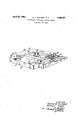
The above-mentioned objects as well as other features of the present invention will become more apparent by reference to the following description taken in conjunction with the accompanying drawing wherein the singlefigure is an isometric view, partly in section, of a circuit board embodying the concept of the present invention.
Referring now to the drawing there is shown a printed circuit board comprising an insulating substrate 10. The substrate has embedded within it a grid of resistive heating elements 12 which, in this instance, are disposed in parallel relationship. The ends of each of these heating elements 12 are connected to respective ones of two bus bars 14 which are located at the edges of the substrate 10, perpendicular to the heating elements 12. The bus bars 14 are similarly embedded within the substrate 10. The bus bars are arranged with two input terminals 13 and 15. Upon the application of a source of input current to these input terminals 13 and 15, a circuit path is completed via the bus bars 14 and the grid system 12. The current flowing through the resistive grid 12 results in the radiation of energy in the form of heat through the substrate 10 causing the temperature of the circuit board to rise; the amount of temperature rise being proportional to the current flow.
1 Claim "ice The embedded input terminals 13 and 15 of the bus bars 14 are projected through the substrate 10 to the top surface 11 thereof via appropriate means, i.e., plated holes 17. Conductive tabs 16 are extended from these surface projections to the terminal edge 18 of the circuit board. A source of input current (not shown) may be connected to these terminal tabs 16 in any one of a number of ways, the most common being through the use of a conventional edge connector.
In the drawing a thermostat 20 is shown mounted on the surface of the circuit board. The thermostate 20 is electrically connected in series, via leads 19, between the source of input current and terminal 15 of the bus bar 14. The thermoelectrical characteristics of the thermostat 20 are calibrated such that the thermostat 20 opens, thereby serving to discontinue current flow through the embedded circuits 14 and 12 whenever the temperature of the circuit board exceeds a predetermined level. The physical orientation of the thermostat 20 is a function of what portion of the circuit board it is desired be temperature controlled. In the case where the entire board is required to be maintained at an even temperature, the thermostat 20 might best be located at the center of the circuit board and calibrated to close only when the temperature of the board drops below a perdetermined v-alue.
Where the elements which require heating can be arranged so as to occupy a smaller portion of the board than the whole, the area to be heated can be localized by breaking the embedded circuit at strategic points. Looking at the drawing, for example, the thermostat 20 has been physically oriented toward the front portion of the embedded grid; i.e., toward edge 18 to which the connector element would be attached. If the temperature sensitive elements which must be maintained within a narrow tmperature range to insure proper operation are mounted toward the front end 18 of the board, in proximity with the thermostat 20, it is unnecessary to provide heat to the rear portion of the board. In such a case two small diameter holes are drilled one through each bus bar 14, as indicated by holes 21 and 23 in the drawing, thereby isolating the rear portion of the embedded circuit from the forward portion and resulting in the discontinuation of current therethrough. Should it be desirable, on the other hand, to localize heat to the rear of the circuit board the appropriate course of action would be to drill a single hole (not shown) through each of the grid elements 12 arranged near the front edge 18 of the board.
In cases where the environmental temperature range to which the circuit board will be exposed is extreme, soft insulation pads (not shown) may be cemented to both sides of the board to isolate the thermostatically controlled system from the environment.
The concept of the present invention need not be limited to single substrate circuit boards having the heating element embedded therein but rather may be expanded to include circuit board assemblies comprising a number of such substrates as well as to circuit board assemblies made up of so-called multilayer circuit boards, in which case the heating circuit would be incorporated upon one of these layers.
What is claimed is:
1. A temperature controlled circuit board comprising:
(a) an insulating substrate, portions of which are to be selectively temperature controlled;
(b) means for providing heating current to said substrate;
(c) a grid circuit embedded within said substrate, said grid circuit characterized by first and second bus bars coupled to said heating means, and further characterized by a plurality of resistive paths intermediate said bus bars, said paths connected in parallel circuit and disposed to substantially span the entire substrate whereby said heating current can be directed via said grid circuit to selectively heat desired portions of said substrate by severing selected elements of said grid proximate the areas of said substrate where heating is not desired; and
(d) a thermostatically controlled switch disposed proximate of said desired portions and connected in circuit with said heating means, said switch adapted to selectively permit or preclude the passage of heating current through the non-severed elements of said grid in response to the temperature of said desired portions.
References Cited UNITED STATES PATENTS Elbert et a1. 219345 Lawson 219-543 Millspaugh et a1. 219446 Bunnell et al. 219-446 US. Cl. X.R.
Applications Claiming Priority (1)
| Application Number | Priority Date | Filing Date | Title |
|---|---|---|---|
| US60587766A | 1966-12-29 | 1966-12-29 |
Publications (1)
| Publication Number | Publication Date |
|---|---|
| US3440407A true US3440407A (en) | 1969-04-22 |
Family
ID=24425568
Family Applications (1)
| Application Number | Title | Priority Date | Filing Date |
|---|---|---|---|
| US605877A Expired - Lifetime US3440407A (en) | 1966-12-29 | 1966-12-29 | Temperature controlled circuit boards |
Country Status (1)
| Country | Link |
|---|---|
| US (1) | US3440407A (en) |
Cited By (25)
| Publication number | Priority date | Publication date | Assignee | Title |
|---|---|---|---|---|
| US3887785A (en) * | 1974-08-29 | 1975-06-03 | Us Air Force | Temperature controlled hybrid oven |
| US4044396A (en) * | 1975-08-14 | 1977-08-23 | The United States Of America As Represented By The Secretary Of The Air Force | Heat pipe cooling of airborne phased array radar |
| US4139763A (en) * | 1978-03-10 | 1979-02-13 | Mcmullan James P | Blanket heater with temperature control means |
| US4277742A (en) * | 1977-01-31 | 1981-07-07 | Panametrics, Inc. | Absolute humidity sensors and methods of manufacturing humidity sensors |
| US4404459A (en) * | 1981-10-19 | 1983-09-13 | The Bendix Corporation | Housing and mounting assembly providing a temperature stabilized environment for a microcircuit |
| US4739382A (en) * | 1985-05-31 | 1988-04-19 | Tektronix, Inc. | Package for a charge-coupled device with temperature dependent cooling |
| US4908696A (en) * | 1986-09-19 | 1990-03-13 | Hitachi, Ltd. | Connector and semiconductor device packages employing the same |
| US5338435A (en) * | 1991-06-26 | 1994-08-16 | Ppg Industries, Inc. | Integrated circuit hydrated sensor apparatus |
| US5342498A (en) * | 1991-06-26 | 1994-08-30 | Graves Jeffrey A | Electronic wiring substrate |
| US5539186A (en) * | 1992-12-09 | 1996-07-23 | International Business Machines Corporation | Temperature controlled multi-layer module |
| US5645123A (en) * | 1993-12-28 | 1997-07-08 | Kabushiki Kaisha Toshiba | Semiconductor device having temperature regulation means formed in circuit board |
| WO1998030075A2 (en) * | 1996-12-31 | 1998-07-09 | Nokia Telecommunications Oy | Method and arrangement for heating a component |
| WO1999059387A1 (en) * | 1998-05-08 | 1999-11-18 | Nokia Networks Oy | A heating method for a printed circuit board and a printed circuit board comprising a heating element |
| WO2001028293A1 (en) * | 1999-10-12 | 2001-04-19 | Xircom, Inc. | Thermally controlled circuit using planar resistive elements |
| US6246581B1 (en) * | 1999-10-12 | 2001-06-12 | International Business Machines Corporation | Heated PCB interconnect for cooled IC chip modules |
| US6262392B1 (en) * | 1997-10-13 | 2001-07-17 | Telefonaktiebolaget Lm Ericsson (Publ) | Printed circuit boards |
| US20010011900A1 (en) * | 1998-08-21 | 2001-08-09 | Hembree David R. | Methods of processing wafers and methods of communicating signals with respect to a wafer |
| US6423940B1 (en) * | 2001-03-02 | 2002-07-23 | Agilent Technologies, Inc. | Temperature stabilization scheme for a circuit board |
| US6472240B2 (en) | 1998-02-27 | 2002-10-29 | Micron Technology, Inc. | Methods of semiconductor processing |
| US20030112446A1 (en) * | 2001-10-26 | 2003-06-19 | Benjamin Miller | Method for biomolecular sensing and system thereof |
| US20040079744A1 (en) * | 2002-10-24 | 2004-04-29 | Bodeau John Michael | Control system for electrostatic discharge mitigation |
| US20050007133A1 (en) * | 1998-08-21 | 2005-01-13 | Hembree David R. | Articles of manufacture and wafer processing apparatuses |
| WO2006077165A1 (en) * | 2005-01-24 | 2006-07-27 | Juma Pcb Gmbh | Printed circuit board or card comprising a heating wire |
| US20130180973A1 (en) * | 2012-01-13 | 2013-07-18 | Gil White | Printed circuit board with embedded heater |
| WO2016005153A1 (en) * | 2014-07-11 | 2016-01-14 | Siemens Aktiengesellschaft | Method for producing an electronic component, and electronic assembly, a heating device being provided in the substrate of the assembly |
Citations (4)
| Publication number | Priority date | Publication date | Assignee | Title |
|---|---|---|---|---|
| US946643A (en) * | 1909-07-12 | 1910-01-18 | George D Westover | Electric stove. |
| US1346793A (en) * | 1916-03-27 | 1920-07-13 | Quincy A Gates | Electric heater |
| US3041441A (en) * | 1960-05-24 | 1962-06-26 | Roland B Elbert | Portable stock warmer |
| US3299253A (en) * | 1963-10-30 | 1967-01-17 | Sierracin Corp | Warming device |
-
1966
- 1966-12-29 US US605877A patent/US3440407A/en not_active Expired - Lifetime
Patent Citations (4)
| Publication number | Priority date | Publication date | Assignee | Title |
|---|---|---|---|---|
| US946643A (en) * | 1909-07-12 | 1910-01-18 | George D Westover | Electric stove. |
| US1346793A (en) * | 1916-03-27 | 1920-07-13 | Quincy A Gates | Electric heater |
| US3041441A (en) * | 1960-05-24 | 1962-06-26 | Roland B Elbert | Portable stock warmer |
| US3299253A (en) * | 1963-10-30 | 1967-01-17 | Sierracin Corp | Warming device |
Cited By (41)
| Publication number | Priority date | Publication date | Assignee | Title |
|---|---|---|---|---|
| US3887785A (en) * | 1974-08-29 | 1975-06-03 | Us Air Force | Temperature controlled hybrid oven |
| US4044396A (en) * | 1975-08-14 | 1977-08-23 | The United States Of America As Represented By The Secretary Of The Air Force | Heat pipe cooling of airborne phased array radar |
| US4277742A (en) * | 1977-01-31 | 1981-07-07 | Panametrics, Inc. | Absolute humidity sensors and methods of manufacturing humidity sensors |
| US4139763A (en) * | 1978-03-10 | 1979-02-13 | Mcmullan James P | Blanket heater with temperature control means |
| US4404459A (en) * | 1981-10-19 | 1983-09-13 | The Bendix Corporation | Housing and mounting assembly providing a temperature stabilized environment for a microcircuit |
| US4739382A (en) * | 1985-05-31 | 1988-04-19 | Tektronix, Inc. | Package for a charge-coupled device with temperature dependent cooling |
| US4908696A (en) * | 1986-09-19 | 1990-03-13 | Hitachi, Ltd. | Connector and semiconductor device packages employing the same |
| US5338435A (en) * | 1991-06-26 | 1994-08-16 | Ppg Industries, Inc. | Integrated circuit hydrated sensor apparatus |
| US5342498A (en) * | 1991-06-26 | 1994-08-30 | Graves Jeffrey A | Electronic wiring substrate |
| US5539186A (en) * | 1992-12-09 | 1996-07-23 | International Business Machines Corporation | Temperature controlled multi-layer module |
| US5645123A (en) * | 1993-12-28 | 1997-07-08 | Kabushiki Kaisha Toshiba | Semiconductor device having temperature regulation means formed in circuit board |
| WO1998030075A2 (en) * | 1996-12-31 | 1998-07-09 | Nokia Telecommunications Oy | Method and arrangement for heating a component |
| WO1998030075A3 (en) * | 1996-12-31 | 1998-08-27 | Nokia Telecommunications Oy | Method and arrangement for heating a component |
| US6262392B1 (en) * | 1997-10-13 | 2001-07-17 | Telefonaktiebolaget Lm Ericsson (Publ) | Printed circuit boards |
| US6472240B2 (en) | 1998-02-27 | 2002-10-29 | Micron Technology, Inc. | Methods of semiconductor processing |
| US6709878B2 (en) | 1998-02-27 | 2004-03-23 | Micron Technology, Inc. | Electronic device workpieces, methods of semiconductor processing and methods of sensing temperature of an electronic device workpiece |
| US20040164372A1 (en) * | 1998-02-27 | 2004-08-26 | Salman Akram | Methods of sensing temperature of an electronic device workpiece |
| US6744346B1 (en) * | 1998-02-27 | 2004-06-01 | Micron Technology, Inc. | Electronic device workpieces, methods of semiconductor processing and methods of sensing temperature of an electronic device workpiece |
| US7419299B2 (en) | 1998-02-27 | 2008-09-02 | Micron Technology, Inc. | Methods of sensing temperature of an electronic device workpiece |
| US6184494B1 (en) | 1998-05-08 | 2001-02-06 | Nokia Networks Oy | Printed circuit board having a heating element and heating method thereof |
| WO1999059387A1 (en) * | 1998-05-08 | 1999-11-18 | Nokia Networks Oy | A heating method for a printed circuit board and a printed circuit board comprising a heating element |
| US20010011900A1 (en) * | 1998-08-21 | 2001-08-09 | Hembree David R. | Methods of processing wafers and methods of communicating signals with respect to a wafer |
| US7148718B2 (en) | 1998-08-21 | 2006-12-12 | Micron Technology, Inc. | Articles of manufacture and wafer processing apparatuses |
| US20050007133A1 (en) * | 1998-08-21 | 2005-01-13 | Hembree David R. | Articles of manufacture and wafer processing apparatuses |
| US7245136B2 (en) | 1998-08-21 | 2007-07-17 | Micron Technology, Inc. | Methods of processing a workpiece, methods of communicating signals with respect to a wafer, and methods of communicating signals within a workpiece processing apparatus |
| US6967497B1 (en) | 1998-08-21 | 2005-11-22 | Micron Technology, Inc. | Wafer processing apparatuses and electronic device workpiece processing apparatuses |
| US6621055B2 (en) * | 1999-10-12 | 2003-09-16 | Intel Corporation | Thermally controlled circuit using planar resistive elements |
| WO2001028293A1 (en) * | 1999-10-12 | 2001-04-19 | Xircom, Inc. | Thermally controlled circuit using planar resistive elements |
| US6246581B1 (en) * | 1999-10-12 | 2001-06-12 | International Business Machines Corporation | Heated PCB interconnect for cooled IC chip modules |
| US6423940B1 (en) * | 2001-03-02 | 2002-07-23 | Agilent Technologies, Inc. | Temperature stabilization scheme for a circuit board |
| US20030112446A1 (en) * | 2001-10-26 | 2003-06-19 | Benjamin Miller | Method for biomolecular sensing and system thereof |
| US6867391B2 (en) * | 2002-10-24 | 2005-03-15 | The Boeing Company | Control system for electrostatic discharge mitigation |
| US20040079744A1 (en) * | 2002-10-24 | 2004-04-29 | Bodeau John Michael | Control system for electrostatic discharge mitigation |
| WO2006077165A1 (en) * | 2005-01-24 | 2006-07-27 | Juma Pcb Gmbh | Printed circuit board or card comprising a heating wire |
| US20080105670A1 (en) * | 2005-01-24 | 2008-05-08 | Markus Wolfel | Printed Circuit Board or Card Comprising a Heating Wire |
| US8481897B2 (en) | 2005-01-24 | 2013-07-09 | Jumatech, Gmbh | Printed circuit board or card comprising a heating wire |
| US20130180973A1 (en) * | 2012-01-13 | 2013-07-18 | Gil White | Printed circuit board with embedded heater |
| US9012811B2 (en) * | 2012-01-13 | 2015-04-21 | Viasystems Technologies Corp. L.L.C. | Printed circuit board with embedded heater |
| WO2016005153A1 (en) * | 2014-07-11 | 2016-01-14 | Siemens Aktiengesellschaft | Method for producing an electronic component, and electronic assembly, a heating device being provided in the substrate of the assembly |
| US20170164465A1 (en) * | 2014-07-11 | 2017-06-08 | Siemens Aktiengesellschaft | Method For Producing An Electronic Component, And Electronic Assembly, A Heating Device Being Provided In The Substrate Of The Assembly |
| US9888559B2 (en) * | 2014-07-11 | 2018-02-06 | Siemens Aktiengesellschaft | Method for producing an electronic component, and electronic assembly, a heating device being provided in the substrate of the assembly |
Similar Documents
| Publication | Publication Date | Title |
|---|---|---|
| US3440407A (en) | Temperature controlled circuit boards | |
| US6300859B1 (en) | Circuit protection devices | |
| US4777434A (en) | Microelectronic burn-in system | |
| WO2001028293A1 (en) | Thermally controlled circuit using planar resistive elements | |
| US6392528B1 (en) | Circuit protection devices | |
| US6184494B1 (en) | Printed circuit board having a heating element and heating method thereof | |
| SE9301825D0 (en) | PROCEDURE AND DEVICE TO PROTECT A SUN CARD against overcurrents | |
| EP1025747B1 (en) | Printed circuit boards | |
| WO2006053386A1 (en) | Flexible pcb thermostrip | |
| US3019283A (en) | Printed circuit board | |
| KR930003483A (en) | Thermal fusion switch and surge absorption circuit using it | |
| US3848111A (en) | Electrical heating unit | |
| US3480837A (en) | Semiconductor circuit assembly | |
| JP2009052898A (en) | Current detection substrate | |
| KR20180076572A (en) | Printed circuit board with circuit pattern including bottlenect section | |
| US3316374A (en) | Thermostat with an improved heat anticipation means | |
| US5361300A (en) | Balancing resistor and thermistor network for telephone circuits, and combination thereof with relay | |
| US20080061921A1 (en) | Device to indicate fuse capacity and electronic apparatus having the same | |
| JP3393981B2 (en) | Thermal protector | |
| JP4092605B2 (en) | Temperature control device for electronic circuit parts | |
| JPH0831458B2 (en) | Superconducting wiring integrated circuit | |
| EP3886534A1 (en) | Flow through heaters | |
| KR20180076569A (en) | Printed circuit board with circuit pattern including bottlenect section | |
| AU2005306582B2 (en) | Flexible PCB thermostrip | |
| JP2000091714A (en) | Temperature adjusting structure for printed board |