US3386128A - Self-actuating, self-locking hinge - Google Patents
Self-actuating, self-locking hinge Download PDFInfo
- Publication number
- US3386128A US3386128A US581862A US58186266A US3386128A US 3386128 A US3386128 A US 3386128A US 581862 A US581862 A US 581862A US 58186266 A US58186266 A US 58186266A US 3386128 A US3386128 A US 3386128A
- Authority
- US
- United States
- Prior art keywords
- hinge
- members
- self
- elements
- hinge elements
- Prior art date
- Legal status (The legal status is an assumption and is not a legal conclusion. Google has not performed a legal analysis and makes no representation as to the accuracy of the status listed.)
- Expired - Lifetime
Links
Images

Classifications
-
- E—FIXED CONSTRUCTIONS
- E05—LOCKS; KEYS; WINDOW OR DOOR FITTINGS; SAFES
- E05D—HINGES OR SUSPENSION DEVICES FOR DOORS, WINDOWS OR WINGS
- E05D1/00—Pinless hinges; Substitutes for hinges
-
- E—FIXED CONSTRUCTIONS
- E05—LOCKS; KEYS; WINDOW OR DOOR FITTINGS; SAFES
- E05D—HINGES OR SUSPENSION DEVICES FOR DOORS, WINDOWS OR WINGS
- E05D1/00—Pinless hinges; Substitutes for hinges
- E05D1/02—Pinless hinges; Substitutes for hinges made of one piece
-
- E—FIXED CONSTRUCTIONS
- E05—LOCKS; KEYS; WINDOW OR DOOR FITTINGS; SAFES
- E05F—DEVICES FOR MOVING WINGS INTO OPEN OR CLOSED POSITION; CHECKS FOR WINGS; WING FITTINGS NOT OTHERWISE PROVIDED FOR, CONCERNED WITH THE FUNCTIONING OF THE WING
- E05F1/00—Closers or openers for wings, not otherwise provided for in this subclass
- E05F1/08—Closers or openers for wings, not otherwise provided for in this subclass spring-actuated, e.g. for horizontally sliding wings
- E05F1/10—Closers or openers for wings, not otherwise provided for in this subclass spring-actuated, e.g. for horizontally sliding wings for swinging wings, e.g. counterbalance
- E05F1/12—Mechanisms in the shape of hinges or pivots, operated by springs
- E05F1/1284—Mechanisms in the shape of hinges or pivots, operated by springs with a leaf or similar spring
Definitions
- the present invention relates to hinges and specifically to a self-actuating, self-locking hinge.
- the hinge described hercin has no pivotal parts to bind and requires no limiting stops. Instead, a plurality of resilient strap-like elements interconnect the members to be hinged, each resilient element being pre-formed to be substantially rigid in its normal extend position, yet being easily folded by making a slight intentional deformation.
- the collective resilient elements are attached to the hinged members in spaced parallel relation to interfit in a compact arrangement when folded in either direction and to form an extremely rigid open box type connecting structure resistant to compression and bending loads when extended.
- FIGURE 1 is a perspective view of the basic hinge structure in open or extended position
- FIGURE 2 is a perspective view of the hinge fully folded
- FIGURE 3 is a side elevation view of the extended hinge
- FIGURE 4 is a side elevation view showing the initial deformation of the hinge elements for folding
- FIGURE 5 is a side elevation view of the fully folded hinge
- FIGURE 6 is a sectional view taken on line 6-6 of FIGURE 3;
- FIGURE 7 is a sectional view similar to FIGURE 6, but showing the hinge elements reversed.
- the two structural members 10 and 12 to be hinged together are shown, for purposes of illustration, as simple rectangular bar or beam members, but could be panels, doors, or other unitary or built up members.
- the only requirement is that the members have suflicient thickness, or at least end portions of sufficient thickness, to space the hinge elements far enough apart for rigidity, as hereinafter described.
- Each hinge element 14 is an elongated, straplike element having a bowed or cambered cross section and being made from metal, plastic, or composite material with sufficient resiliency to return to its normal shape when deformed. At least one hinge element 14 is attached to each side of the members 12 and 14, the preferred minimum being two on one side and one on the other in a triangular arrangement when viewed in section, as in FIGURE 6. This provides torsional rigidity and maintains alignment of the two connected members.
- the hinge elements 14 are staggered on opposite sides and spaced in parallel relation so that the hinge element from one side can pass alongside or between those on the other side without contact.
- the ends of the hinge elements are secured to members It) and 12 by screws 16, or any other suitable means depending on the material and structure of the members.
- the members 10 and 12 are spaced apart at a distance slightly more than the combined thickness of the confronting ends 18 and 20, the hinge elements 14 bridging the gap and forming a boxlike open frame structure. As illustrated in FIGURES l to 6, the hinge elements are secured with their convex faces 22 against the members.
- hinge elements can also be secured with their concave faces 24 toward the members, as in FIG- URE 7, with small filler blocks 26 inserted to prevent flattening of the elements by their attachment screws.
- Each hinge element has inherent stiffness due to its bowed or cambered cross section and will resist bending in either direction, although more so when bent toward the convex side than to the concave side.
- the box-like frame arrangement joining the two structural members, with corresponding sides of the hinge elements facing each other will have considerable resistance to bending and will maintain a rigid coupling.
- the members In the folded position the members can be restrained by any suitable means, according to the nature of the structure. When released, the natural resiliency of the hinge element 14 will snap the assembly to the extended, rigid position without any assistance.
- any required number of hinge elements may be used, the elements being staggered in spaced relation on opposite sides of the members, as indicated on the member 34 in FIGURE 8. Regardless of the number of elements used the hinge will fold in either direction.
- the hinge structure make it ideal for use on spacecraft for such operations as extending solar cell panels, antennas, booms and the like.
- the self-actuating feature eliminates the need for special drive or operating mechanisms and greatly increases the reliability of operation. Many other uses will be apparent, such as for folding doors, screens, or the like.
- a self-actuating, self-locking hinge for interconnecting a pair of adjacent members, the confronting edge portions of which have a certain thickness, the hinge comprising:
- hinge elements being secured to both sides of the members and thus spaced apart by the thickness of the members to form a box-like open frame structure connecting the members.
- hinge elements are staggered on opposite sides of the 4 members and spaced apart so that the hinge elements on one side, when folded, can pass alongside and between the hinge elements on the other side.
- hinge elements all have the correspondingly curved faces thereof disposed toward the members.
Landscapes
- Engineering & Computer Science (AREA)
- Mechanical Engineering (AREA)
- Casings For Electric Apparatus (AREA)
Description
June 4, 1968 w. w. VYVYAN 3,386,128
SELF-ACTUATING, SELF-LOCKING HINGE Filed Sept. 26, 1966 I 2 Sheets-Sheet 1 [N VENTOR.
WESLEY W. VYVYAN BY maww June 4, 1968 w. w. VYVYAN 3,386,128
SELF-ACTUATING, SELF-LOCKING HINGE Filed Sept. 26, 1966 2 Sheets-Sheet 2 INVENTOR. WESLEY W. VYVYAN United States Patent 3,386,128 SELF-ACTUATING, SELF-LOCKING HINGE Wesley W. Vyvyan, San Diego, Calif., assignor to The Ryan Aeronautical Co., San Diego, Calif. Filed Sept. 26, 1966, Ser. No. 581,862 4 Claims. (Cl. 16-150) The present invention relates to hinges and specifically to a self-actuating, self-locking hinge.
Various types of self-opening hinges have been developed, usually involving a conventional pin centered hinge with a spring device attached to spread, or at least assist in spreading the hinge. To hold the hinge in a specific open position some type of stop or locking mechanism must be incorporated. This type of hinge is subject to binding or jamming to the extent that the spring cannot open the hinge properly, particularly after prolonged storage or non-use, or under adverse environmental conditions.
The hinge described hercin has no pivotal parts to bind and requires no limiting stops. Instead, a plurality of resilient strap-like elements interconnect the members to be hinged, each resilient element being pre-formed to be substantially rigid in its normal extend position, yet being easily folded by making a slight intentional deformation. The collective resilient elements are attached to the hinged members in spaced parallel relation to interfit in a compact arrangement when folded in either direction and to form an extremely rigid open box type connecting structure resistant to compression and bending loads when extended.
The hinge and its operation are illustrated in the drawings, in which:
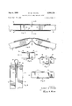
FIGURE 1 is a perspective view of the basic hinge structure in open or extended position;
FIGURE 2 is a perspective view of the hinge fully folded;
FIGURE 3 is a side elevation view of the extended hinge;
FIGURE 4 is a side elevation view showing the initial deformation of the hinge elements for folding;
FIGURE 5 is a side elevation view of the fully folded hinge;
FIGURE 6 is a sectional view taken on line 6-6 of FIGURE 3;
FIGURE 7 is a sectional view similar to FIGURE 6, but showing the hinge elements reversed; and
FIGURE 8 is a sectional view of a multiple element hinge for large members.
Similar characters of reference indicate similar or identical elements and portions throughout the specification and throughout the views of the drawing.
The two structural members 10 and 12 to be hinged together are shown, for purposes of illustration, as simple rectangular bar or beam members, but could be panels, doors, or other unitary or built up members. The only requirement is that the members have suflicient thickness, or at least end portions of sufficient thickness, to space the hinge elements far enough apart for rigidity, as hereinafter described.
Each hinge element 14 is an elongated, straplike element having a bowed or cambered cross section and being made from metal, plastic, or composite material with sufficient resiliency to return to its normal shape when deformed. At least one hinge element 14 is attached to each side of the members 12 and 14, the preferred minimum being two on one side and one on the other in a triangular arrangement when viewed in section, as in FIGURE 6. This provides torsional rigidity and maintains alignment of the two connected members. The hinge elements 14 are staggered on opposite sides and spaced in parallel relation so that the hinge element from one side can pass alongside or between those on the other side without contact. The ends of the hinge elements are secured to members It) and 12 by screws 16, or any other suitable means depending on the material and structure of the members.
It should be noted that the members 10 and 12 are spaced apart at a distance slightly more than the combined thickness of the confronting ends 18 and 20, the hinge elements 14 bridging the gap and forming a boxlike open frame structure. As illustrated in FIGURES l to 6, the hinge elements are secured with their convex faces 22 against the members.
However, the hinge elements can also be secured with their concave faces 24 toward the members, as in FIG- URE 7, with small filler blocks 26 inserted to prevent flattening of the elements by their attachment screws. Each hinge element has inherent stiffness due to its bowed or cambered cross section and will resist bending in either direction, although more so when bent toward the convex side than to the concave side. Thus the box-like frame arrangement joining the two structural members, with corresponding sides of the hinge elements facing each other, will have considerable resistance to bending and will maintain a rigid coupling.
To fold the hinge it is only necessary to deform the hinge element on one side by flattening the central portion 28 and pressing the element inwardly between the members 10 and 12, as in FIGURE 4. By so collapsing one side of the box frame structure the hinge elements on the other side can be bent back with a minimum of effort. Continuing the folding action will cause the deformed hinge element to bow inwardly and pass between the hinge elements on the other side, the latter being stretched across the ends 18 and 20. In the fully folded position the members 10 and 12 are in closely spaced parallel relation, with just sufficient space therebetween for the now return folded hinge element whose looped portion 30 projects beyond the ends of the members. It will now be evident why the members 10 and 12 must be spaced apart in the extended position as mentioned above. The spacing is sufiicient to allow the bridging portions 32 of the hinge elements now on the outside of the hinge to extend across the combined thickness of ends 18 and 20 and leave space between the members for the return folded hinge element.
In the folded position the members can be restrained by any suitable means, according to the nature of the structure. When released, the natural resiliency of the hinge element 14 will snap the assembly to the extended, rigid position without any assistance.
For wide members or panels, any required number of hinge elements may be used, the elements being staggered in spaced relation on opposite sides of the members, as indicated on the member 34 in FIGURE 8. Regardless of the number of elements used the hinge will fold in either direction.
The light weight and simplicity of the hinge structure make it ideal for use on spacecraft for such operations as extending solar cell panels, antennas, booms and the like. In addition, the self-actuating feature eliminates the need for special drive or operating mechanisms and greatly increases the reliability of operation. Many other uses will be apparent, such as for folding doors, screens, or the like.
It is understood that minor variation from the form of the invention disclosed herein may be made without departure from the spirit and scope of the invention, and that the specification and drawings are to be considered as merely illustrative rather than limiting.
I claim:
1. A self-actuating, self-locking hinge for interconnecting a pair of adjacent members, the confronting edge portions of which have a certain thickness, the hinge comprising:
a plurality of elongated, strap-like hinge elements of resilient material each having a cambered cross section;
the ends of said hinge elements being secured to the pair of members with the confronting edges of the members spaced apart and the hinge elements bridging the gap therebetween in substantially parallel relation;
said hinge elements being secured to both sides of the members and thus spaced apart by the thickness of the members to form a box-like open frame structure connecting the members.
2. The structure according to claim 1, wherein said hinge elements are staggered on opposite sides of the 4 members and spaced apart so that the hinge elements on one side, when folded, can pass alongside and between the hinge elements on the other side.
3. The structure according to claim 1, wherein said hinge elements all have the correspondingly curved faces thereof disposed toward the members.
4. The structure according to claim 1, wherein the confronting edges of the members are spaced apart a distance slightly greater than the combined thickness of the confronting edges.
References Cited UNITED STATES PATENTS 2,526,129 10/1950 Groesbeck et a1. 16-150 BOBBY R. GAY, Primary Examiner.
Claims (1)
1. A SELF-ACTUATING, SELF-LOCKING HINGE FOR INTERCONNECTING A PAIR OF ADJACENT MEMBERS, THE CONFRONTING EDGE PORTIONS OF WHICH HAVE A CERTAIN THICKNESS, THE HINGE COMPRISING: A PLURALITY OF ELONGATED, STRAP-LIKE HINGE ELEMENTS OF RESILIENT MATERIAL EACH HAVING A CAMBERED CROSS SECTION; THE ENDS OF SAID HINGE ELEMENTS BEING SECURED TO THE PAIR OF MEMBERS WITH THE CONFRONTING EDGES OF THE MEMBERS SPACED APART AND THE HINGE ELEMENTS BRIDGING THE GAP THEREBETWEEN IN SUBSTANTIALLY PARALLEL RELATION; SAID HINGE ELEMENTS BEING SECURED TO BOTH SIDES OF THE MEMBERS AND THUS SPACED APART BY THE THICKNESS OF THE MEMBERS TO FORM A BOX-LIKE OPEN FRAME STRUCTURE CONNECTING THE MEMBERS.
Priority Applications (1)
| Application Number | Priority Date | Filing Date | Title |
|---|---|---|---|
| US581862A US3386128A (en) | 1966-09-26 | 1966-09-26 | Self-actuating, self-locking hinge |
Applications Claiming Priority (1)
| Application Number | Priority Date | Filing Date | Title |
|---|---|---|---|
| US581862A US3386128A (en) | 1966-09-26 | 1966-09-26 | Self-actuating, self-locking hinge |
Publications (1)
| Publication Number | Publication Date |
|---|---|
| US3386128A true US3386128A (en) | 1968-06-04 |
Family
ID=24326877
Family Applications (1)
| Application Number | Title | Priority Date | Filing Date |
|---|---|---|---|
| US581862A Expired - Lifetime US3386128A (en) | 1966-09-26 | 1966-09-26 | Self-actuating, self-locking hinge |
Country Status (1)
| Country | Link |
|---|---|
| US (1) | US3386128A (en) |
Cited By (45)
| Publication number | Priority date | Publication date | Assignee | Title |
|---|---|---|---|---|
| US3474488A (en) * | 1967-08-24 | 1969-10-28 | Bendix Corp | Foldable and compressible self-erecting devices |
| US3670358A (en) * | 1970-04-29 | 1972-06-20 | Hughes Aircraft Co | Self actuating self locking flexible hinge |
| US3701295A (en) * | 1970-06-03 | 1972-10-31 | Nakamura Seisakkusho Kk | Torque wrench |
| US4163303A (en) * | 1977-09-13 | 1979-08-07 | G. D. Hanna Incorporated | Hinge structure |
| FR2635077A1 (en) * | 1988-08-08 | 1990-02-09 | Aerospatiale | SELF-MOTORIZED ARTICULATION, WITHOUT FRICTION, AND ARTICULATED ASSEMBLY SUCH AS A SOLAR SATELLITE PANEL EQUIPPED WITH SUCH ARTICULATIONS |
| FR2756028A1 (en) * | 1996-11-19 | 1998-05-22 | Metravib Sa | SELF-PROPELLED, SELF-LOCKING AND SHOCK ABSORBING JOINT AND ARTICULATION EQUIPPED WITH SUCH JOINTS |
| WO1998022343A1 (en) * | 1996-11-19 | 1998-05-28 | Metravib R.D.S. | Automotive, self-locking and damping articulated joint and articulation equipped with same |
| US20020056248A1 (en) * | 1999-11-09 | 2002-05-16 | Foster-Miller, Inc. | Foldable member |
| US20030019180A1 (en) * | 1999-11-09 | 2003-01-30 | Warren Peter A. | Foldable member |
| FR2846298A1 (en) * | 2002-10-29 | 2004-04-30 | Cit Alcatel | ARTICULATED ASSEMBLY OF SOLAR GENERATOR PANELS AND SPATIAL VEHICLE |
| FR2846297A1 (en) * | 2002-10-29 | 2004-04-30 | Cit Alcatel | Articulated assembly of solar panels for space vehicle, comprises panels linked by Carpentier joints, stacked as concertina, retained by pyrotechnic cables and released to form rigid structure |
| FR2853624A1 (en) | 2003-04-14 | 2004-10-15 | Eads Launch Vehicles | Device e.g. solar generator, components assembly for space craft, has cushion folded such that components are found, two by two, on both sides of cushions fold |
| EP1468912A1 (en) | 2003-04-14 | 2004-10-20 | EADS SPACE Transportation SA | Variable geometry structure for a device on board of a spacecraft |
| US20050022465A1 (en) * | 1999-11-09 | 2005-02-03 | Warren Peter A. | Flexible, deployment rate damped hinge |
| US6910304B2 (en) | 2002-04-02 | 2005-06-28 | Foster-Miller, Inc. | Stiffener reinforced foldable member |
| JP2006054808A (en) * | 2004-08-16 | 2006-02-23 | Matsushita Electric Ind Co Ltd | Folding portable terminal |
| US20070053504A1 (en) * | 2003-10-31 | 2007-03-08 | Matsushita Electric Industrial Co., Ltd. | Connection device, electronic apparatus with the same, and folding portable terminal device |
| US20070253648A1 (en) * | 2006-04-26 | 2007-11-01 | Evergreen Innovation Partners, Llc | Deployable and disposable container assemblies and associated systems and methods |
| WO2007141478A1 (en) * | 2006-06-06 | 2007-12-13 | Qinetiq Limited | A self opening hinges |
| FR2908366A1 (en) * | 2006-11-15 | 2008-05-16 | Cera | Boot covering shelf for motor vehicle, has stop zones being in support against each other to prevent rotation of panels to correspond retracted configuration to unstable curved configuration, and to suppress support between stop zones |
| US20080190949A1 (en) * | 2007-02-12 | 2008-08-14 | Aaron Charles Rosso | Magnetic insulator pad for container |
| US7435032B1 (en) | 2006-08-08 | 2008-10-14 | The United States Of America As Represented By The Secretary Of The Air Force | Resilient joint for deployable structures |
| EP2000407A2 (en) | 2007-06-05 | 2008-12-10 | HTS Hochtechnologie Systeme GmbH | Self-locking hinge device |
| US20090184207A1 (en) * | 2008-01-22 | 2009-07-23 | Warren Peter A | Synchronously self deploying boom |
| US20090282646A1 (en) * | 2006-06-23 | 2009-11-19 | Thales | Self-driven articulation for an articulated assembly such as a satellite solar panel |
| US20100185291A1 (en) * | 2008-12-31 | 2010-07-22 | Jimenez Omar F | Methods and apparatus for vertebral body distraction and fusion employing flexure members |
| US20100319270A1 (en) * | 2009-06-18 | 2010-12-23 | Astrium Limited | Extendable structure |
| US20110138948A1 (en) * | 2009-07-22 | 2011-06-16 | Jimenez Omar F | Coaxial screw gear sleeve mechanism |
| US8628577B1 (en) | 2009-03-19 | 2014-01-14 | Ex Technology, Llc | Stable device for intervertebral distraction and fusion |
| US8636746B2 (en) | 2009-12-31 | 2014-01-28 | Spinex Tec, Llc | Methods and apparatus for insertion of vertebral body distraction and fusion devices |
| US20140373654A1 (en) * | 2013-06-21 | 2014-12-25 | First Dome Corporation | Dual-shaft synchronous movement device |
| US8940049B1 (en) | 2014-04-01 | 2015-01-27 | Ex Technology, Llc | Expandable intervertebral cage |
| US20150083642A1 (en) * | 2013-09-23 | 2015-03-26 | Glamglow Inc. | Container with an exterior reversible strip and method for making the same |
| US9486328B2 (en) | 2014-04-01 | 2016-11-08 | Ex Technology, Llc | Expandable intervertebral cage |
| US20170185104A1 (en) * | 2015-12-24 | 2017-06-29 | Intel Corporation | Orbiting Hinge |
| RU2636207C1 (en) * | 2015-11-10 | 2017-11-21 | Федеральное государственное бюджетное образовательное учреждение высшего образования "Сибирский государственный университет науки и технологий имени академика М.Ф. Решетнева" (СибГУ им. М.Ф. Решетнева) | Satellite vehicle variable mechanical systems deployment device |
| RU2641398C2 (en) * | 2012-12-05 | 2018-01-17 | Таль | Device for deployment and folding of flexible structure, flexible deployable structure and satellite, equipped with such device |
| EP3326920A1 (en) * | 2016-11-28 | 2018-05-30 | Centre National D'Études Spatiales (C N E S) | Deployable structure with spontaneous deployment |
| JP2018532648A (en) * | 2015-10-26 | 2018-11-08 | 徐府實業股▲ふん▼有限公司Shyu Fuu Industrial Co.,Ltd. | Folding sunshade |
| US10443648B2 (en) * | 2015-12-21 | 2019-10-15 | Airbus Ds Gmbh | Hinge assembly for a space structure |
| US20190335702A1 (en) * | 2018-05-02 | 2019-11-07 | Kids Ii, Inc. | Universal dynamic hinge for a foldable apparatus |
| US10676217B2 (en) * | 2017-11-10 | 2020-06-09 | Spire Global, Inc. | Deployable satellite solar panel hinge mechanism |
| US11234835B2 (en) | 2019-03-05 | 2022-02-01 | Octagon Spine Llc | Transversely expandable minimally invasive intervertebral cage |
| US11497622B2 (en) | 2019-03-05 | 2022-11-15 | Ex Technology, Llc | Transversely expandable minimally invasive intervertebral cage and insertion and extraction device |
| RU2788221C1 (en) * | 2022-09-22 | 2023-01-17 | Акционерное общество "Информационные спутниковые системы" имени академика М.Ф. Решетнёва" | Flexible hinge assembly |
Citations (1)
| Publication number | Priority date | Publication date | Assignee | Title |
|---|---|---|---|---|
| US2526129A (en) * | 1947-10-31 | 1950-10-17 | Savage Arms Corp | Flexible hinge |
-
1966
- 1966-09-26 US US581862A patent/US3386128A/en not_active Expired - Lifetime
Patent Citations (1)
| Publication number | Priority date | Publication date | Assignee | Title |
|---|---|---|---|---|
| US2526129A (en) * | 1947-10-31 | 1950-10-17 | Savage Arms Corp | Flexible hinge |
Cited By (96)
| Publication number | Priority date | Publication date | Assignee | Title |
|---|---|---|---|---|
| US3474488A (en) * | 1967-08-24 | 1969-10-28 | Bendix Corp | Foldable and compressible self-erecting devices |
| US3670358A (en) * | 1970-04-29 | 1972-06-20 | Hughes Aircraft Co | Self actuating self locking flexible hinge |
| US3701295A (en) * | 1970-06-03 | 1972-10-31 | Nakamura Seisakkusho Kk | Torque wrench |
| US4163303A (en) * | 1977-09-13 | 1979-08-07 | G. D. Hanna Incorporated | Hinge structure |
| FR2635077A1 (en) * | 1988-08-08 | 1990-02-09 | Aerospatiale | SELF-MOTORIZED ARTICULATION, WITHOUT FRICTION, AND ARTICULATED ASSEMBLY SUCH AS A SOLAR SATELLITE PANEL EQUIPPED WITH SUCH ARTICULATIONS |
| EP0354837A1 (en) | 1988-08-08 | 1990-02-14 | AEROSPATIALE Société Nationale Industrielle | Frictionless self-erecting joint and articulated assembly, e.g. a solar panel for a satellite provided with said joints |
| US5086541A (en) * | 1988-08-08 | 1992-02-11 | Aerospatiale Societe Nationale Industrielle | Self-motorized antifriction joint and an articulated assembly, such as a satellite solar panel, equipped with such joints |
| CN1083789C (en) * | 1996-11-19 | 2002-05-01 | 梅特拉维比R·D·S·有限公司 | Automotive, self-locking and damping articulated joint and articulation equipped with same |
| US6334235B2 (en) * | 1996-11-19 | 2002-01-01 | Metravib, R.D.S. | Self-driving, self-locking and damping hinge strap, and a hinge fitted with such straps |
| WO1998022343A1 (en) * | 1996-11-19 | 1998-05-28 | Metravib R.D.S. | Automotive, self-locking and damping articulated joint and articulation equipped with same |
| FR2756028A1 (en) * | 1996-11-19 | 1998-05-22 | Metravib Sa | SELF-PROPELLED, SELF-LOCKING AND SHOCK ABSORBING JOINT AND ARTICULATION EQUIPPED WITH SUCH JOINTS |
| US8074324B2 (en) * | 1999-11-09 | 2011-12-13 | Foster-Miller, Inc. | Flexible, deployment rate damped hinge |
| US20020056248A1 (en) * | 1999-11-09 | 2002-05-16 | Foster-Miller, Inc. | Foldable member |
| US20030019180A1 (en) * | 1999-11-09 | 2003-01-30 | Warren Peter A. | Foldable member |
| US20050022465A1 (en) * | 1999-11-09 | 2005-02-03 | Warren Peter A. | Flexible, deployment rate damped hinge |
| US6910304B2 (en) | 2002-04-02 | 2005-06-28 | Foster-Miller, Inc. | Stiffener reinforced foldable member |
| FR2846297A1 (en) * | 2002-10-29 | 2004-04-30 | Cit Alcatel | Articulated assembly of solar panels for space vehicle, comprises panels linked by Carpentier joints, stacked as concertina, retained by pyrotechnic cables and released to form rigid structure |
| US7513461B2 (en) | 2002-10-29 | 2009-04-07 | Thales | Articulated assembly of solar generator panels and space vehicle |
| WO2004039673A1 (en) * | 2002-10-29 | 2004-05-13 | Alcatel | Articulated assembly of solar generator panels and space vehicle |
| EP1415909A1 (en) * | 2002-10-29 | 2004-05-06 | Alcatel | Articulated solar generator panel assembly and spacecraft |
| JP2006517487A (en) * | 2002-10-29 | 2006-07-27 | アルカテル | Solar panel hinged assembly and spacecraft |
| FR2846298A1 (en) * | 2002-10-29 | 2004-04-30 | Cit Alcatel | ARTICULATED ASSEMBLY OF SOLAR GENERATOR PANELS AND SPATIAL VEHICLE |
| US20060049317A1 (en) * | 2002-10-29 | 2006-03-09 | Alcatel | Articulated assembly of solar generator panels and space vehicle |
| EP1468912A1 (en) | 2003-04-14 | 2004-10-20 | EADS SPACE Transportation SA | Variable geometry structure for a device on board of a spacecraft |
| US20040245402A1 (en) * | 2003-04-14 | 2004-12-09 | Eads Space Transportation Sa | Foldable and deployable assembly of elements mounted on board a spacecraft |
| US7093804B2 (en) | 2003-04-14 | 2006-08-22 | Eads Space Transportation Sa | Foldable and deployable assembly of elements mounted on board a spacecraft |
| JP2004314944A (en) * | 2003-04-14 | 2004-11-11 | Eads Space Transporation Sa | Folding connection structure of developing structural body for mounting to spaceship |
| FR2853624A1 (en) | 2003-04-14 | 2004-10-15 | Eads Launch Vehicles | Device e.g. solar generator, components assembly for space craft, has cushion folded such that components are found, two by two, on both sides of cushions fold |
| US20070053504A1 (en) * | 2003-10-31 | 2007-03-08 | Matsushita Electric Industrial Co., Ltd. | Connection device, electronic apparatus with the same, and folding portable terminal device |
| JP2006054808A (en) * | 2004-08-16 | 2006-02-23 | Matsushita Electric Ind Co Ltd | Folding portable terminal |
| US20070253648A1 (en) * | 2006-04-26 | 2007-11-01 | Evergreen Innovation Partners, Llc | Deployable and disposable container assemblies and associated systems and methods |
| US9469474B2 (en) | 2006-04-26 | 2016-10-18 | Evergreen Innovation Partners I, Lp | Deployable and disposable container assemblies with bendable support members |
| US8556100B2 (en) | 2006-04-26 | 2013-10-15 | Evergreen Innovation Partners LLP | Deployable and disposable container assemblies with bendable support members |
| US8070006B2 (en) * | 2006-04-26 | 2011-12-06 | Evergreen Innovation Partners I, Lp | Deployable and disposable container assemblies with bendable support members |
| WO2007141478A1 (en) * | 2006-06-06 | 2007-12-13 | Qinetiq Limited | A self opening hinges |
| US20100163684A1 (en) * | 2006-06-06 | 2010-07-01 | Qinetiq Limited | Self opening hinges |
| US8151414B2 (en) * | 2006-06-23 | 2012-04-10 | Thales | Self-driven articulation for an articulated assembly such as a satellite solar panel |
| US20090282646A1 (en) * | 2006-06-23 | 2009-11-19 | Thales | Self-driven articulation for an articulated assembly such as a satellite solar panel |
| US7435032B1 (en) | 2006-08-08 | 2008-10-14 | The United States Of America As Represented By The Secretary Of The Air Force | Resilient joint for deployable structures |
| FR2908366A1 (en) * | 2006-11-15 | 2008-05-16 | Cera | Boot covering shelf for motor vehicle, has stop zones being in support against each other to prevent rotation of panels to correspond retracted configuration to unstable curved configuration, and to suppress support between stop zones |
| US20080190949A1 (en) * | 2007-02-12 | 2008-08-14 | Aaron Charles Rosso | Magnetic insulator pad for container |
| EP2000407A2 (en) | 2007-06-05 | 2008-12-10 | HTS Hochtechnologie Systeme GmbH | Self-locking hinge device |
| DE102007026452B4 (en) * | 2007-06-05 | 2010-09-09 | Hts - Hoch Technologie Systeme Gmbh | Self locking hinge device |
| DE102007026452B8 (en) * | 2007-06-05 | 2010-12-16 | Hts - Hoch Technologie Systeme Gmbh | Self locking hinge device |
| EP2000407A3 (en) * | 2007-06-05 | 2013-11-13 | HTS Hochtechnologie Systeme GmbH | Self-locking hinge device |
| DE102007026452A1 (en) | 2007-06-05 | 2008-12-11 | Hts - Hoch Technologie Systeme Gmbh | Self locking hinge device |
| US20090184207A1 (en) * | 2008-01-22 | 2009-07-23 | Warren Peter A | Synchronously self deploying boom |
| US9381092B2 (en) | 2008-12-31 | 2016-07-05 | Ex Technology, Llc | Flexible joint arrangement incorporating flexure members |
| US8906100B2 (en) | 2008-12-31 | 2014-12-09 | Ex Technology, Llc | Methods and apparatus for vertebral body distraction and fusion employing flexure members |
| US10060469B2 (en) | 2008-12-31 | 2018-08-28 | Ex Technology, Llc | Flexible joint arrangement incorporating flexure members |
| US8523944B2 (en) | 2008-12-31 | 2013-09-03 | Spinex Tec, Llc | Methods and apparatus for vertebral body distraction and fusion employing flexure members |
| US8540452B2 (en) | 2008-12-31 | 2013-09-24 | Spinex Tec, Llc | Flexible joint arrangement incorporating flexure members |
| US20100185291A1 (en) * | 2008-12-31 | 2010-07-22 | Jimenez Omar F | Methods and apparatus for vertebral body distraction and fusion employing flexure members |
| US9445917B2 (en) | 2008-12-31 | 2016-09-20 | Ex Technology, Llc | Methods and apparatus for expandable medical device employing flexure members |
| US20100209184A1 (en) * | 2008-12-31 | 2010-08-19 | Jimenez Omar F | Flexible joint arrangement incorporating flexure members |
| US8628577B1 (en) | 2009-03-19 | 2014-01-14 | Ex Technology, Llc | Stable device for intervertebral distraction and fusion |
| US9867717B2 (en) | 2009-03-19 | 2018-01-16 | Ex Technology, Llc | Stable device for intervertebral distraction and fusion |
| US20100319270A1 (en) * | 2009-06-18 | 2010-12-23 | Astrium Limited | Extendable structure |
| US9714519B2 (en) * | 2009-06-18 | 2017-07-25 | Astrium Limited | Extendable structure |
| US8771360B2 (en) | 2009-07-22 | 2014-07-08 | Spinex Tec, Llc | Methods and apparatuses for vertebral body distraction and fusion employing a coaxial screw gear sleeve mechanism |
| US10117757B2 (en) | 2009-07-22 | 2018-11-06 | Spinex Tec, Llc | Coaxial screw gear sleeve mechanism |
| US20110160861A1 (en) * | 2009-07-22 | 2011-06-30 | Jimenez Omar F | Methods and apparatuses for vertebral body distraction and fusion employing a coaxial screw gear sleeve mechanism |
| US10369008B2 (en) | 2009-07-22 | 2019-08-06 | Spinex Tec Llc | Medical device employing a coaxial screw gear sleeve mechanism |
| US9358125B2 (en) | 2009-07-22 | 2016-06-07 | Spinex Tec, Llc | Coaxial screw gear sleeve mechanism |
| US11026804B2 (en) | 2009-07-22 | 2021-06-08 | Spinex Tec, Llc | Coaxial screw gear sleeve mechanism |
| US20110138948A1 (en) * | 2009-07-22 | 2011-06-16 | Jimenez Omar F | Coaxial screw gear sleeve mechanism |
| US9474626B2 (en) | 2009-07-22 | 2016-10-25 | Spinex Tec Llc | Methods and apparatuses for vertebral body distraction and fusion employing a coaxial screw gear sleeve mechanism |
| US11612496B2 (en) | 2009-07-22 | 2023-03-28 | Spinex Tec Llc | Medical device employing a coaxial screw gear sleeve mechanism |
| US8303663B2 (en) | 2009-07-22 | 2012-11-06 | Spinex Tec, Llc | Methods and apparatuses for vertebral body distraction and fusion employing a coaxial screw gear sleeve mechanism |
| US8636746B2 (en) | 2009-12-31 | 2014-01-28 | Spinex Tec, Llc | Methods and apparatus for insertion of vertebral body distraction and fusion devices |
| US9498270B2 (en) | 2011-07-22 | 2016-11-22 | SpineX Tee, LLC | Methods and apparatus for insertion of vertebral body distraction and fusion devices |
| US8932302B2 (en) | 2011-07-22 | 2015-01-13 | Spinex Tec, Llc | Methods and apparatus for insertion of vertebral body distraction and fusion devices |
| RU2641398C2 (en) * | 2012-12-05 | 2018-01-17 | Таль | Device for deployment and folding of flexible structure, flexible deployable structure and satellite, equipped with such device |
| US8959719B2 (en) * | 2013-06-21 | 2015-02-24 | First Dome Corporation | Dual-shaft synchronous movement device |
| US20140373654A1 (en) * | 2013-06-21 | 2014-12-25 | First Dome Corporation | Dual-shaft synchronous movement device |
| US20150083642A1 (en) * | 2013-09-23 | 2015-03-26 | Glamglow Inc. | Container with an exterior reversible strip and method for making the same |
| US8940049B1 (en) | 2014-04-01 | 2015-01-27 | Ex Technology, Llc | Expandable intervertebral cage |
| US10687963B2 (en) | 2014-04-01 | 2020-06-23 | Ex Technology, Llc | Expandable intervertebral cage |
| US11471301B2 (en) | 2014-04-01 | 2022-10-18 | Ex Technology, Llc | Expandable intervertebral cage |
| US10052214B2 (en) | 2014-04-01 | 2018-08-21 | Ex Technology, Llc | Expandable intervertebral cage |
| US9668879B2 (en) | 2014-04-01 | 2017-06-06 | Ex Technology, Llc | Expandable intervertebral cage |
| US9486328B2 (en) | 2014-04-01 | 2016-11-08 | Ex Technology, Llc | Expandable intervertebral cage |
| JP2018532648A (en) * | 2015-10-26 | 2018-11-08 | 徐府實業股▲ふん▼有限公司Shyu Fuu Industrial Co.,Ltd. | Folding sunshade |
| RU2636207C1 (en) * | 2015-11-10 | 2017-11-21 | Федеральное государственное бюджетное образовательное учреждение высшего образования "Сибирский государственный университет науки и технологий имени академика М.Ф. Решетнева" (СибГУ им. М.Ф. Решетнева) | Satellite vehicle variable mechanical systems deployment device |
| US10443648B2 (en) * | 2015-12-21 | 2019-10-15 | Airbus Ds Gmbh | Hinge assembly for a space structure |
| US20170185104A1 (en) * | 2015-12-24 | 2017-06-29 | Intel Corporation | Orbiting Hinge |
| US9964989B2 (en) * | 2015-12-24 | 2018-05-08 | Intel Corporation | Orbiting hinge |
| EP3326920A1 (en) * | 2016-11-28 | 2018-05-30 | Centre National D'Études Spatiales (C N E S) | Deployable structure with spontaneous deployment |
| FR3059304A1 (en) * | 2016-11-28 | 2018-06-01 | Centre National D'etudes Spatiales C N E S | DEPLOYABLE STRUCTURE WITH SPONTANEOUS DEPLOYMENT |
| US10676217B2 (en) * | 2017-11-10 | 2020-06-09 | Spire Global, Inc. | Deployable satellite solar panel hinge mechanism |
| US11691766B2 (en) | 2017-11-10 | 2023-07-04 | Spire Global Subsidiary, Inc. | Deployable satellite solar panel hinge mechanism |
| US20190335702A1 (en) * | 2018-05-02 | 2019-11-07 | Kids Ii, Inc. | Universal dynamic hinge for a foldable apparatus |
| US11497622B2 (en) | 2019-03-05 | 2022-11-15 | Ex Technology, Llc | Transversely expandable minimally invasive intervertebral cage and insertion and extraction device |
| US11234835B2 (en) | 2019-03-05 | 2022-02-01 | Octagon Spine Llc | Transversely expandable minimally invasive intervertebral cage |
| US11911292B2 (en) | 2019-03-05 | 2024-02-27 | Octagon Spine Llc | Transversely expandable minimally invasive intervertebral cage |
| RU2788221C1 (en) * | 2022-09-22 | 2023-01-17 | Акционерное общество "Информационные спутниковые системы" имени академика М.Ф. Решетнёва" | Flexible hinge assembly |
Similar Documents
| Publication | Publication Date | Title |
|---|---|---|
| US3386128A (en) | Self-actuating, self-locking hinge | |
| US918570A (en) | Seal. | |
| US3749133A (en) | Strain energy erectile tubular beam with stitched flanges | |
| GB1572580A (en) | Building components for constructing frames, enclosures and the like | |
| US1698136A (en) | Two-way hinge | |
| US5320239A (en) | Case with pivoting cover and elastic articulation | |
| US3832756A (en) | Dual action hinge for folding doors | |
| KR920019637A (en) | Combined straps with integral coupling structure and anti-disassembly characteristics | |
| US3474488A (en) | Foldable and compressible self-erecting devices | |
| US3206897A (en) | Folding structure fabricated of rigid panels | |
| US3225474A (en) | Display device | |
| US3532373A (en) | Link operated opposed jaw latch | |
| US3385344A (en) | Bi-fold door structure | |
| US2578964A (en) | Folding awning frame | |
| WO2007019926A1 (en) | Item of cabinet furniture | |
| US3191218A (en) | Hinge structures with multiple pintles | |
| US2888055A (en) | Wallet card holding and display book and clamp therefor | |
| US1916882A (en) | Collapsible strut | |
| DE102015117461A1 (en) | Support system for adjusting a headrest | |
| US1955492A (en) | Folding table | |
| DE3601682C2 (en) | Single-joint hinge with locking latch | |
| US1661164A (en) | Door check and holder | |
| US2150878A (en) | Folding table | |
| US1609556A (en) | Hinged connection | |
| DE74109C (en) | Portfolio, wallet or the like. With a resilient back part and with this resiliently connected lids |