US3290522A - Nuclear emission electrical generator - Google Patents
Nuclear emission electrical generator Download PDFInfo
- Publication number
- US3290522A US3290522A US438279A US43827965A US3290522A US 3290522 A US3290522 A US 3290522A US 438279 A US438279 A US 438279A US 43827965 A US43827965 A US 43827965A US 3290522 A US3290522 A US 3290522A
- Authority
- US
- United States
- Prior art keywords
- pole pieces
- charged particles
- cloud
- flux
- magnetic
- Prior art date
- Legal status (The legal status is an assumption and is not a legal conclusion. Google has not performed a legal analysis and makes no representation as to the accuracy of the status listed.)
- Expired - Lifetime
Links
Images
Classifications
-
- G—PHYSICS
- G21—NUCLEAR PHYSICS; NUCLEAR ENGINEERING
- G21H—OBTAINING ENERGY FROM RADIOACTIVE SOURCES; APPLICATIONS OF RADIATION FROM RADIOACTIVE SOURCES, NOT OTHERWISE PROVIDED FOR; UTILISING COSMIC RADIATION
- G21H1/00—Arrangements for obtaining electrical energy from radioactive sources, e.g. from radioactive isotopes, nuclear or atomic batteries
Definitions
- This invention relates to the derivation of electrical energy from the energy of charged particles derived from the alteration of the nucleus of an atom.
- An object of this invention is to provide an apparatus that develops useful electrical energy from the energy of charged particles derived from the fission of radioactive material.
- Another object of the invention is to provide an apparatus that utilizes the electric field developed by the kinetic energy of charged particles to produce electrical energy.
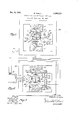
- FIG. 1 is ⁇ a schematic sectional view of an apparatus according to the invention
- FIG. 2 is a schematic sectional view of another ernbodiment of the invention.
- FIG. 3 illustrates the current loops.
- the embodiment of the invention provides electrical power by modulating the density of a cloud of charged particles rconfined within an enclosed space by a magnetic field.
- the variation in the density of the cloud of charged particles causes a variation in the magnetic field created by the cloud.
- This variation cuts an electrically conductive means to create an electric potential and current therein according to Faradays Law of Induction.
- the density of the cloud of charged particles may be varied by impressing a periodically varying electrostatic field or a periodically varying electromagnetic field on the confined cloud of charged particles.
- the electrical energy is derived from the kinetic energy imparted to the charged particles on the 4occur-rence of a fission of a radioactive material.
- a radioactive source which emits charged particles, such as beta particles or electrons, is placed in a magnetic field so that when the particles are emitted they are captured within the electromagnetic field and travel in a helical path having ⁇ an axis generally in the same direction as the axis of the magnet.
- the pole pieces have a configuration such that the lines of force ⁇ are convex outwardly between the poles, the magnetic tiux density being greater near the poles than at a midpoint between the poles. Also, at the midpoint between the poles the lines of force are parallel to the Z axis while departing more and more from the parallelism as the poles are approached.
- the charged particles of the cloud are in constant motion between the pole pieces.
- the size and density of the cloud of charged particles may be varied by altering the fields of force acting upon and confining the particles.
- radioactive material as a thin layer in the form of a hollow sphere 10 is positioned at the center of a larger enclosing hollow sphere 11, preferably made of glass.
- the inner surface of the glass sphere is coated with a thin layer of silver 12.
- Sphere 10 may be supported by columns 13 secured to the glass sphere 11.
- the sphere 11 is centrally positioned between the permanent magnet pieces 14 and 15 with pole pieces 16 and 17, respectively.
- the magnet pieces are connected by a yoke 38.
- the permanent magnet pieces are preferably nrade of Alnico and the pole pieces are made of ferrite and have convex surfaces 19 and 20.
- the magnetic Vfield extending between the pole pieces 16 and 17 has a curved shape with the lines of force concentrating at the surfaces 19, 20 and bows outwardly so that the flux density is least in the plane midway between the surfaces 19 and 20.
- the sphere 11 may be supported by insulating blocks 21 and 22 fitting between the sphere and the surfaces 19 and 20.
- the thin laye-r of radioactive material in sphere 10 may be made of the element strontium which emits charged particles ⁇ at any angle to the X, Y and Z ordinates illustrated in dotted lines in FIG. l.
- the charged particles having a component of velocity along the X or the Y ordinate cut the lines of force of the magnetic field and due to the high flux density and the charge on the particle, the particle curves and circles to travel in a helical path having its axis generally parallel to the Z ordinate.
- the converging lines of force of the magnetic field cause the radius of the helical path of the particle to contract and the change in direction of the magnetic lines of force cause the charged particle to reverse its direction along the Z axis so that it travels towards the opposite pole.
- This focusing action causes the charged particle to oscillate back and forth between the pole pieces.
- the radioactive source provides a vast quantity of these charged particles which forms a dense cloud within the hollow sphere 11.
- the charged particles emitted by the radioactive sou-rce that travels along the Z ordinate are not .affected by the magnetic field, since they are traveling parallel to the lines of force. These particles and other particles, the major portion of whose velocity is in the Z direction, are collected by the silver lining 12 and accumulate thereon to create an electrostatic charge between the silver lining 12 ⁇ and the hollow sphere 1.0. Since the charged particles On the silver lining are of the same polarity as the charged particles of the cloud within the hollow sphere, the electrostatic charge on the silver lining 12 causes the cloud to be compressed or increased in density.
- the hollow sphere 10 and the silver lining 12 are connected to a gas discharge tube 23 by means of leads 241i and 25, respectively.
- the lead 24 extends through an insulator 26 in the wall of the hollow sphere 11.
- This ⁇ action is repetitive and is essentially a relaxation oscillator.
- An external variable condenser 27 may he connected across the gaseous discharge tube 23 to vary the capacity of the circuit and hence the rapidity of discharge of the gaseous discharge tube, and thereby the frequency of the pulsations of the charged cloud.
- An electrical conductive means 28 may comprise tWo electrically conductive loops 29 and 30 with spaced ends connected to line conductors 31 and 32.
- the charged cloud on contracting and expanding, induces in the loops an electric current and potential which is removed by conducto-rs 31 and 32.
- the radioactive material may be one gram of strontium 90 formed as a hollow sphere with an inside diameter of 9 mm. and an outside diameter of 11.36 mm., resulting in a thickness of 1.18 mm.
- strontium 90 decomposes with a half life of 20 years to yield yttrium 90 and a beta particle.
- Yttrium 90 is also radioactive and has a half life of 6l hours.
- Yttrium 90 yields zirconium 90 and Ia beta particle. Zirconium 90 is stable.
- the amperage from one gram of strontium 90 and Y yttrium90 ⁇ in equilibrium amount is 2.36 10-6 amperes.
- the beta particles of maximum energy will circle in an orbit having a diameter of approximately 4 cm. Since beta particles revolve in an orbit on both sides of the inner sphere, the inside diameter of the outer sphere should be at least 9.5 cm.
- the inner sphere 110 and the outer shell 11 have a capacity of 0.730 micromicrofarad. If the gas is discharged at a breakdown voltage of 1,000 Volts, the frequency of discharge will be 540 cycles per second.
- the external variable condenser 27 may have la maximum capacity of 10 micromicrofarads, making the total capacity of the circuit 10.730 micromicrofarads. With this total capacity in the circuit, the frequency of discharge is 36.60 cycles per second.
- a range from 540 to 36.60 cycles per second may be provided with a discharge tube having a breakdown voltage of 1,000 volts and Ia 10 micromicrofarad variable condenser. Further variation of the frequency may be obtained by varying the discharge voltage of the tube 23.
- the radius of revolution of the orbit of the charged particle is calculated by dividing 8885 gauss cm. by 4400 gauss. This results in an orbital radius of 2.02 cm. or an orbital diameter lof 4.04 cm. Since space for two orbits is required .along with space for the radioactive sphere, the inner diameter of the outer sphere should be at least of the order of 9.5 cm.
- the capacity between the inner shell tand outer sphere is 0.730 micromicrofarad and is determined as follows:
- a radioactive source is in the form of a thin hollow sphere 110 with an inside diameter of 0.9 cm. and an outside diameter of 1.136 cm. providing a wall thickness of 0.118 cm.
- the sphere is made of strontium which emits charged particles.
- the sphere is positioned at the center of a larger enclosing hollow sphere 111, preferably made of glass and having an inside diameter of 9.5 cm.
- the inner surface of the glass sphere is coated with a thin layer of silver 112.
- the sphere 111 is centrally posi* tioned between the Alnico permanent magnet pieces 33, 34 with pole pieces 36, 3'7 preferably made of ferrite and having surfaces 39, 40.
- a yoke 3S preferably made of soft iron, connects the Alnico magnet pieces 33 and 34 to provide a flux therebetween and the Alnico magnet pieces are arranged so that the pole piece 36 is a north pole and the pole piece 37 is a south pole.
- the convex surfaces 39 and 40 shape the magnetic eld between the pole pieces with a slight curvature so that the iield has the general shape of a barrel or staves of a barrel.
- the pole pieces 36 and 37 have extensions 41 and 42 with an electrical coil 43 wound around the extensions 41 and 4Z to provide a variable iiux to the pole pieces 36 and 37 to modulate the magnetic ield extending between the pole pieces.
- the spheres 110 and 111 are centrally positioned in the field. As indicated in FIG. 2, the magnetic iiux is symmetric around the Z ordinate.
- the pole pieces are preferably 9.5 cm. in diameter and the Alnico magnets provide a field strength in the order of 4,400 gauss.
- the pole pieces 36 and 37 are spaced preferably 9.5 cm. apart.
- the glass sphere 111 is centrally positioned between the pole pieces 36 and 37 so that the inner sphere 110 is at the center of the magnetic field.
- the cloud of charged particles is formed in a manner' similar to the embodiment of FIG. 1. However, the cloud is modulated by varying the magnetic iield rather than the electrostatic field.
- the charge of the particles collected by the silver lining 112 is returned to the inner sphere 110 by means of electrically conducting lead 44, resistor 45 and electrically conducting lead 46 passing through the outer sphere 111 and the silver lining 112 by means of an insulator 47 electrically isolating lead 46 from the lining 112.
- an insulator 47 electrically isolating lead 46 from the lining 112.
- the extensions 41, 42 are positioned so as not to materially affect the symmetry of the iluX between the pole pieces 36 and 37 and may be provided with an air gap 48 to increase the reluctance of the magnetic path but still permit a magnetic coupling through the winding 43.
- the coil 43 and the extensions 41 and 42 are formed so that when the proper current is passed through the winding 43, a magnetic iux is formed in the extensions 41 and 42 that passes therethrough to the pole piece 36 across the space between the pole pieces 36 and 37 to vary the permanent flux created by the Alnico magnet pieces 33 and 34.
- This variation causes the charged cloud to be compressed on an increase of the ux density and to expand on a decrease of the iiux density.
- the variation in the sizes of the charged cloud within the sphere 110 causes the variation in the magnetic field produced by the charged cloud.
- the cloud comprises a large number of charged particles all rotating in the same direction about their respective axes. Since the cloud is within a confined space, the particles are moving in the same direction at the periphery of the cloud to provide a magnetic iield coupled with the conductive loops.
- the modulated magnetic field of the magnets acts on the individual particles causing their orbits to contract and expand.
- the particles forming the cloud cause the field of the cloud to contract and expand delivering the energy of the circulating particles to the conductive means as electrical energy.
- the electrical conductive means 50 may comprise an upper loop 51a and a lower loop 52a, each formed with a split so that the ends of the loops are connected to the conductors 51, S2 in parallel.
- loops 51a, 52a each has a small cross section in a plane containing the magnet axis in comparison to the conductive path (FIG. 3).
- the coil -43 may be connected to an independent alternating source of electrical energy S5.
- a portion of the current may be tapped by a transformer means 56 to stop the operation of the alternating source 55 and supply the current to the coil 43.
- the electrons which strike the silver lining or shield 112 are electrically connected to the radioactive source 110 through the resistance 45 and are not utilized to modulate the charged cloud.
- the modulation is achieved by passing an initial alternating current from the source S5 to the coil 43.
- This alternating current alters the lines of force which flow through the auxiliary pole pieces 4l, 42 and varies the flux density of the main flux.
- the main magnetic ux is thereby cyclically changed and the charged cloud cyclically contracts and expands further changing the magnetic field in passing through the loops 51a and 52a.
- the conductors are carrying suicient alternating current the source 55 is cut out and the device is self-exciting.
- the two above-described methods for varying the cloud of charged particles set forth in connection with FIGS. 1 and 2 can be combined.
- the condenser-discharged current could be fed to the gas-discharged cell by means of a winding around the auxiliary gap. This combination will increase the efficiency of the device.
- the maximum energy of beta from yttriu-m 90 is 2.2 mev.
- the average energy as measured recently is 0.895 mev. This is 40.7% of the maximum value.
- the shape of the external condenser shell was chosen as a hollow sphere for illustrative purposes because of the ease of computation. Other shapes could .be used and the shape will be determined by the shape of the pole pieces and the shape of the radioactive source.
- the ⁇ outer shell should probably be made :of a nonconductor lined with a very thin layer .of a conductor or metal. This is necessary because if an unsupported metal shell is used, it would, of necessity, have to be relatively thick and in a thick shell parasitic currents would be induced which would cut down on the usable power derived.
- the source used in the above example is one made of strontium metal. While there are a number of advantages in using this material, any convenient beta emitter can be used. Further, for positively charged particles any alpha emitter can be used. Moreover, the substance producing beta rays may be created in the apparatus. A device of this sort would be a neutron-producing source surrounded by a substance which would produce beta rays by decomposition after being struck by and absorbing a neutron. Most natural elements will absorb neutrons and then spontaneously decompose giving 01T beta rays. An example of such a combination would be a polonium-beryllium source surrounded by a shell of natural, non-radioactive, yttrium metal, yttrium 89.
- the polonium yields alpha particles which impinge on the beryllium yielding neutrons.
- the neutrons would strike the yttrium 89 yielding yttrium 90 plus gamma radiation.
- the yttrium 90 would then decompose with a half life of 6l hours to give a beta ray and zirconium 90.
- the advantage of this latter type of source is that it is not tied to the half life of the original isotope. There are only a few isotopes known of median half life like strontium 90.
- Apparatus for producing electric voltage and current comprising means spaced along an axis for producing ux increasing in density in .opposite directions from an intermediate plane therebetween transverse to the axis for confining charged particles within the flux, enclosing means forming an evacuated space between said spaced means, means for producing charged particles mounted in said evacuated space of said enclosing means and positioned in a plane from which the flux produced by said spaced means increases in density on opposite sides thereof for confining charged particles created by .said means producing charged particles as a cloud of charged particles with an external field, means for periodically varyin-g the density of the flux confining the charged particles to vary the cloud of charged particles and the external eld thereof, electrical conductive means for delivery of current to a circuit and being electrically separate from said means rfor periodically varying the density of the flux confining the charged particles as a cloud of charged particles, said electrical conductive means substantially surrounding said evacuated space formed by said enclosing means and extending transverse to the axis and the
- apparatus for producing electric voltage and current comprislng a pair of magnetic pole pieces spaced along a central axis for producing flux increasing in density in opposite directions from an intermediate plane therebetween transverse to the axis for confining charged particles Within the ux, enclosing means forming an evacuated space between said spaced pole pieces, means for producing charged particles mounted in said evacuated ⁇ space of said enclosing means and positioned between said pole pieces to create charged particles defiected ⁇ by the flux tocalc within the fiux as a charged cloud having an external field, means for periodically varying the density of the fiux confining the charged particles to vary the cloud of charged particles and the external field thereof, electrical conductive means for delivery of current to a circuit and being electrically separate from said means for periodically varying the density of the flux, said electrical conductive means extending transverse to the central axis and having a radial width to the central axis substantially less than the length of the conductive means and substantially surrounding said evacuated space formed by said enclosing means to be positioned
- An apparatus for producing an electric voltage coinprising a pair of spaced magnetic pole pieces means defining a medium of low permeability between said spaced pole pieces traversed by the magnetic flux of said pole pieces, a radioactive source located between said pole pieces within said medium to create between said pole pieces charged particles, said pole pieces forming a magnetic flux around said radioactive source and increasing in flux density from an intermediate plane traversing said medium to defiect the charged particles to orbit within said fiux with a kinetic energy produced in the creation of said particles and creating a charged cloud having an external magnetic field and contained within said medium by the flux of said pole pieces, conductive means between said pole pieces and located within the external eld of the charged particles, means for periodically varying the den- Sity of the flux confining the charged particles to vary the size of the cloud of charged particles and the external field thereof to create a voltage in the conductive means by the movement of the external field.
- An apparatus for producing an electric voltage comprising a pair of spaced magnetic pole pieces, means defining a medium ⁇ of? low permeability between said spaced pole pieces traversed by the magnetic fiux of said pole pieces, a radioactive source located between said pole pieces within said medium to create between said pole pieces charged particles, said pole pieces forming a magnetic flux around said radioactive source and increasing in fiux density from an intermediate plane traversing said medium to deflect the charged particles to orbit within said flux with a kinetic energy produced in the creation of said particles and creating a charged cloud having an external magnetic field and contained within said medium by the flux of said pole pieces, conductive means between said pole pieces and located within the external field of the charged particles, a lconductive shield surrounding said radioactive source and spaced therefrom to form a chamber for containing the cloud of charged particles and receive a potential to change the size of said cloud, and means for temporarily discharging said potential to return the size of the cloud ⁇ of charged particles to noncharge size.
- An apparatus for producing an electric voltage comprising a pair of spaced magnetic pole pieces, means defining a medium of low permeability between said spaced pole pieces traversed by the magnetic fiux of said pole pieces, a radioactive source located between said pole pieces within said medium to create between said pole pieces charged particles, said pole pieces forming a magnetic flux around said radioactive source and increasing in fiux density from an intermediate plane traversing said medium to deflect the charged particles to orbit within said flux with a kinetic energy produced in the creation of said particles and creating a charged cloud having an external magnetic field and contained within said medium by the flux of said pole pieces, conductive means between said pole pieces and located within the external field of the charged particles, and means for varying the flux of said spaced magnetic pole pieces for varying the spatial orientation of the cloud of charged particles and the external field thereof to create a voltage in said conductive means.
- An apparatus for producing an electric voltage comprising a pair of spaced magnetic pole pieces, means defining a medium of low permeability between said spaced pole pieces traversed by the magnetic fiux of said pole pieces, a radioactive source located between said pole pieces within said medium to create between said pole pieces charged particles, said pole pieces forming a magnetic flux around said radioactive source and increasing in fiux density from an intermediate plane traversing said medium to deflect lthe charged particles to orbit within said flux with a kinetic energy produced in the creation of said particles and creating a charged cloud having an external magnetic field and contained within said medium by the flux of said pole pieces, conductive means between said pole pieces and located within the external field of the charged particles, an auxiliary pair of pole pieces magnetically coupled to said spaced magnetic pole pieces, a coil around said auxiliary pole pieces, an external source of energy coupled with said coil for producing oscillations therein to vary the fiux of said spaced magnetic pole pieces for varying the spatial orientation of the cloud of charged particles to alter the position of the external field to create a voltage in said conductive means.
- a method for the conversion of the kinetic energy of a charged particles to useful energy comprising producing a magnetic field increasing in fiux density on opposite sides of a transverse plane, producing charged particles having trajectories in planes transverse to the magnetic lines of force and curving the trajectories by the magnetic lines of force into complete orbits within the magnetic field and restricting the longitudinal movement of the charged particles by the increase in flux density to form a cloud of charged particles with the peripheral charged particles of a given charge moving in the same direction to create an electrical field in a given direction at the periphery of the cloud, modulating the magnetic field to vary the size of the cloud and the spatial orientation of the electrical field and creating current and voltage in wirelike means encompassing the cloud by the change in spatial orientation of the electrical field thus extracting the kinetic energy of the charged particles as current and voltage in the wirelike means.
Description
Dec. 6, 1966 R. GINELL NUCLEAR EMISSION ELECTRICAL GENERATOR Original Filed Aug. 28, 1956 Clar/0 0f JQ Nm 37m 52 30 a 52a United States 8 Claims. (Si. S10- 3) This application is a continuation of my copending application Serial No. 606,708 iiled August 28, 1956, now abandoned, which was copending with and a continuationin-part o-f my application Serial No. 413,068 filed March 1, 1954, now abandoned, and each entitled Nuclear Emission Electrical Generator.
This invention relates to the derivation of electrical energy from the energy of charged particles derived from the alteration of the nucleus of an atom.
An object of this invention is to provide an apparatus that develops useful electrical energy from the energy of charged particles derived from the fission of radioactive material.
Another object of the invention is to provide an apparatus that utilizes the electric field developed by the kinetic energy of charged particles to produce electrical energy.
Other and further objects and advantages will be apparent from the following description taken in connection with the drawings in which FIG. 1 is `a schematic sectional view of an apparatus according to the invention;
FIG. 2 is a schematic sectional view of another ernbodiment of the invention; and
FIG. 3 illustrates the current loops.
In general, the embodiment of the invention provides electrical power by modulating the density of a cloud of charged particles rconfined within an enclosed space by a magnetic field. The variation in the density of the cloud of charged particles causes a variation in the magnetic field created by the cloud. This variation cuts an electrically conductive means to create an electric potential and current therein according to Faradays Law of Induction. The density of the cloud of charged particles may be varied by impressing a periodically varying electrostatic field or a periodically varying electromagnetic field on the confined cloud of charged particles. The electrical energy is derived from the kinetic energy imparted to the charged particles on the 4occur-rence of a fission of a radioactive material.
According to an embodiment of this invention, a radioactive source which emits charged particles, such as beta particles or electrons, is placed in a magnetic field so that when the particles are emitted they are captured within the electromagnetic field and travel in a helical path having `an axis generally in the same direction as the axis of the magnet. The pole pieces have a configuration such that the lines of force `are convex outwardly between the poles, the magnetic tiux density being greater near the poles than at a midpoint between the poles. Also, at the midpoint between the poles the lines of force are parallel to the Z axis while departing more and more from the parallelism as the poles are approached. Thus, near the midpoint particles will tend to travel in helical paths upward and downward towards the poles. However, when they approach the poles, due to the change in the direction of the lines of force, their Z component will be reversed so that the charged particles will travel in a helical path back and forth between the poles, reversing in direction of travel when they approach the pole pieces. Thus, the charged particles of the cloud are in constant motion between the pole pieces. The size and density of the cloud of charged particles may be varied by altering the fields of force acting upon and confining the particles.
atent Referring specifically to FIG. 1, radioactive material as a thin layer in the form of a hollow sphere 10 is positioned at the center of a larger enclosing hollow sphere 11, preferably made of glass. The inner surface of the glass sphere is coated with a thin layer of silver 12. Sphere 10 may be supported by columns 13 secured to the glass sphere 11. The sphere 11 is centrally positioned between the permanent magnet pieces 14 and 15 with pole pieces 16 and 17, respectively. The magnet pieces are connected by a yoke 38. The permanent magnet pieces are preferably nrade of Alnico and the pole pieces are made of ferrite and have convex surfaces 19 and 20. The magnetic Vfield extending between the pole pieces 16 and 17 has a curved shape with the lines of force concentrating at the surfaces 19, 20 and bows outwardly so that the flux density is least in the plane midway between the surfaces 19 and 20. The sphere 11 may be supported by insulating blocks 21 and 22 fitting between the sphere and the surfaces 19 and 20.
The thin laye-r of radioactive material in sphere 10 may be made of the element strontium which emits charged particles `at any angle to the X, Y and Z ordinates illustrated in dotted lines in FIG. l. The charged particles having a component of velocity along the X or the Y ordinate cut the lines of force of the magnetic field and due to the high flux density and the charge on the particle, the particle curves and circles to travel in a helical path having its axis generally parallel to the Z ordinate. As the particle moves towards either the pole 16 or 17, the converging lines of force of the magnetic field cause the radius of the helical path of the particle to contract and the change in direction of the magnetic lines of force cause the charged particle to reverse its direction along the Z axis so that it travels towards the opposite pole. This focusing action causes the charged particle to oscillate back and forth between the pole pieces. The radioactive source provides a vast quantity of these charged particles which forms a dense cloud within the hollow sphere 11.
The charged particles emitted by the radioactive sou-rce that travels along the Z ordinate (having no X or Y velocity component) are not .affected by the magnetic field, since they are traveling parallel to the lines of force. These particles and other particles, the major portion of whose velocity is in the Z direction, are collected by the silver lining 12 and accumulate thereon to create an electrostatic charge between the silver lining 12 `and the hollow sphere 1.0. Since the charged particles On the silver lining are of the same polarity as the charged particles of the cloud within the hollow sphere, the electrostatic charge on the silver lining 12 causes the cloud to be compressed or increased in density.
The hollow sphere 10 and the silver lining 12 are connected to a gas discharge tube 23 by means of leads 241i and 25, respectively. The lead 24 extends through an insulator 26 in the wall of the hollow sphere 11. Thus, the silver lining 2 and the sphere 10 are connected across the discharge tube 23 to place the electrostatic charge across the elements of the tube. When the electrostatic charge reaches given value the gaseous discharge tube lires, equalizing the potenti-als of the sphere 10 and the lining 12 so that there is little or no electrostatic charge on the sphere 11. As the charge is removed, the cloud of charged particles expands. When the voltage falls to a predetermined low value, the gas discharge tube is extinguished `and the potential on sphere 11 is again increased. This `action is repetitive and is essentially a relaxation oscillator. An external variable condenser 27 may he connected across the gaseous discharge tube 23 to vary the capacity of the circuit and hence the rapidity of discharge of the gaseous discharge tube, and thereby the frequency of the pulsations of the charged cloud.
An electrical conductive means 28 may comprise tWo electrically conductive loops 29 and 30 with spaced ends connected to line conductors 31 and 32. The charged cloud, on contracting and expanding, induces in the loops an electric current and potential which is removed by conducto- rs 31 and 32.
In a specific embodiment of the aforementioned described unit, the radioactive material may be one gram of strontium 90 formed as a hollow sphere with an inside diameter of 9 mm. and an outside diameter of 11.36 mm., resulting in a thickness of 1.18 mm. strontium 90 decomposes with a half life of 20 years to yield yttrium 90 and a beta particle. Yttrium 90 is also radioactive and has a half life of 6l hours. Yttrium 90 yields zirconium 90 and Ia beta particle. Zirconium 90 is stable.
The amperage from one gram of strontium 90 and Y yttrium90` in equilibrium amount is 2.36 10-6 amperes.
When the magnet provides a eld of 4,400 gauss, the beta particles of maximum energy will circle in an orbit having a diameter of approximately 4 cm. Since beta particles revolve in an orbit on both sides of the inner sphere, the inside diameter of the outer sphere should be at least 9.5 cm. The inner sphere 110 and the outer shell 11 have a capacity of 0.730 micromicrofarad. If the gas is discharged at a breakdown voltage of 1,000 Volts, the frequency of discharge will be 540 cycles per second. The external variable condenser 27 may have la maximum capacity of 10 micromicrofarads, making the total capacity of the circuit 10.730 micromicrofarads. With this total capacity in the circuit, the frequency of discharge is 36.60 cycles per second. Thus, a range from 540 to 36.60 cycles per second may be provided with a discharge tube having a breakdown voltage of 1,000 volts and Ia 10 micromicrofarad variable condenser. Further variation of the frequency may be obtained by varying the discharge voltage of the tube 23.
The value .Z.36 106 amperes is derived as follows:
The specic rate constant of strontium 90 is The amount decomposing in unit time, t, will be x=A(1-e-kt) where x is the amount decomposed at time, t, k=speciic rate constant Ao=starting amount (amount at t=0) e=base of natural longarithrns=2-71828*L t=time.
For the first hour of operation at equilibrium let A0=1 gm. strontium 90 t=1 hour Jc=0.044 -6 atomic wts./hr. (decomposed per gm.
Srso) x=2.65 10+16 atoms decomposed/hr.
x=2.65 10+16 beta rays produced/hr. per gm. Sr90 Jc=7.36 1012 beta nays/sec. per gm. Sr90 since 96,500 amperes=6-02 1023 electrons/sec. hence x=1.8 10-6 amperes This is the amperage obtained from one gram of strontium 90 over the iirst hour of its life. Since one beta is obtained from yttriurn 90 for each beta from In deriving the value of 4,400 gauss the motion of the charged particle is taken into consideration. For a moving electron Where m which is the mass of the particle is a variable factor which, according to the Einstein Theory of Relativity, varies with the velocity of the particle. This theory has been verified in this respect. According to this theory strontium 90, the total amperage obtained from this sys- Y tem is twice this ligure or Total amperage=2-36 10-6 amperes mil-(allow where mo=rest mass of particle (here the electron) v=velocity of the particle c=velocity of light.
Since the velocity of the electron from Sr and Y9 is so great, this relativity correction must be taken into account. Inserting this equation and the equation v=bc into the previous equation, we have in calculating the value of HR. The terms on the right, m0, c, 'and e are known constants leaving only b to be determined. The velocity of a particle is a function of its energy .and the relationship is given by Einsteins law as E: (m-m)c2 where E=the energy of the particle Inserting the value of m from where 1 n 1 @2)1/2 i.e.,
m=nmo E n l +m0c2 and From these equations if we use the known energy of the particles from the Sr90-Y90 system we can calculate HR. For the Srm--Y90 system the maximum energy contained in any emitted particle is 2.2 m.e.v. Hence, using E=2.2 m.e.v.
n=5.31 and Using the previous equation HR=1704 bn HR=8885 gauss cm.
With the magnetic iield of 4,400 gauss, the radius of revolution of the orbit of the charged particle is calculated by dividing 8885 gauss cm. by 4400 gauss. This results in an orbital radius of 2.02 cm. or an orbital diameter lof 4.04 cm. Since space for two orbits is required .along with space for the radioactive sphere, the inner diameter of the outer sphere should be at least of the order of 9.5 cm.
The capacity between the inner shell tand outer sphere is 0.730 micromicrofarad and is determined as follows:
where C=capacity of the condenser in farfads r1=radius of the external shield rzrztradius of the internal spheres K=dielectric constant of the internal space, in this case :1.
m=9 1011 statfarads/farad and Q :E C
where E=EMF of charge in volts Q=Quantity of electricity in coulombs.
1n this system the radioactive sphere is emitting a xed current of beta rays (coulornbs/sec.) hence,
where A=Amperage of source j=Frequency of discharge in cycles/ sec.
combining the equations A(r1-r2)m f Erp2 A=2.36 106 tamperes not consideringy self-absorption. If a 50% loss for self-absorption is allowed, the emitting amperage is 1.18)(10-5 tamperes. One third of these electrons will be captured by the spherical shell so that the charging `current will be 1/a (1.18 X10⁻⁶) amperes.
Since the magnet strength is 4,400 gauss, then as previously calculated the radius of revolution of the electrons of maximum energy will ybe approximately 2 cm., and the outer spherical shell will be 9.5 cm. in diameter. r1=4.75 cm.; r2=0.57 cm. so that 1.18 10-6(4.75W0.57)9 10111 f* a 4.7.5(057 E fem farad 6 When the discharge voltage is at 1,000 volts, then the frequency is 36.60 cycle/ sec. When the discharge voltage is reduced to 500 volts, then the frequency is 73.20 cycles/sec. Since the external condenser is variable, the voltage can be adjusted to the characteristics of the discharge tube or to any other desired value.
In FIG. 2 an embodiment is shown in which a radioactive source is in the form of a thin hollow sphere 110 with an inside diameter of 0.9 cm. and an outside diameter of 1.136 cm. providing a wall thickness of 0.118 cm. The sphere is made of strontium which emits charged particles. The sphere is positioned at the center of a larger enclosing hollow sphere 111, preferably made of glass and having an inside diameter of 9.5 cm. The inner surface of the glass sphere is coated with a thin layer of silver 112. The sphere 111 is centrally posi* tioned between the Alnico permanent magnet pieces 33, 34 with pole pieces 36, 3'7 preferably made of ferrite and having surfaces 39, 40. A yoke 3S, preferably made of soft iron, connects the Alnico magnet pieces 33 and 34 to provide a flux therebetween and the Alnico magnet pieces are arranged so that the pole piece 36 is a north pole and the pole piece 37 is a south pole. The convex surfaces 39 and 40 shape the magnetic eld between the pole pieces with a slight curvature so that the iield has the general shape of a barrel or staves of a barrel. The pole pieces 36 and 37 have extensions 41 and 42 with an electrical coil 43 wound around the extensions 41 and 4Z to provide a variable iiux to the pole pieces 36 and 37 to modulate the magnetic ield extending between the pole pieces.
The spheres 110 and 111 are centrally positioned in the field. As indicated in FIG. 2, the magnetic iiux is symmetric around the Z ordinate. The pole pieces are preferably 9.5 cm. in diameter and the Alnico magnets provide a field strength in the order of 4,400 gauss. The pole pieces 36 and 37 are spaced preferably 9.5 cm. apart. The glass sphere 111 is centrally positioned between the pole pieces 36 and 37 so that the inner sphere 110 is at the center of the magnetic field.
The cloud of charged particles is formed in a manner' similar to the embodiment of FIG. 1. However, the cloud is modulated by varying the magnetic iield rather than the electrostatic field. The charge of the particles collected by the silver lining 112 is returned to the inner sphere 110 by means of electrically conducting lead 44, resistor 45 and electrically conducting lead 46 passing through the outer sphere 111 and the silver lining 112 by means of an insulator 47 electrically isolating lead 46 from the lining 112. Thus, a charge is prevented from accumulating on the lining 112 in relation to the inner sphere 110 that would inliuence the charged cloud within the sphere 111.
The extensions 41, 42 are positioned so as not to materially affect the symmetry of the iluX between the pole pieces 36 and 37 and may be provided with an air gap 48 to increase the reluctance of the magnetic path but still permit a magnetic coupling through the winding 43. The coil 43 and the extensions 41 and 42 are formed so that when the proper current is passed through the winding 43, a magnetic iux is formed in the extensions 41 and 42 that passes therethrough to the pole piece 36 across the space between the pole pieces 36 and 37 to vary the permanent flux created by the Alnico magnet pieces 33 and 34. This variation causes the charged cloud to be compressed on an increase of the ux density and to expand on a decrease of the iiux density. The variation in the sizes of the charged cloud within the sphere 110 causes the variation in the magnetic field produced by the charged cloud.
The cloud comprises a large number of charged particles all rotating in the same direction about their respective axes. Since the cloud is within a confined space, the particles are moving in the same direction at the periphery of the cloud to provide a magnetic iield coupled with the conductive loops. The modulated magnetic field of the magnets acts on the individual particles causing their orbits to contract and expand. The particles forming the cloud cause the field of the cloud to contract and expand delivering the energy of the circulating particles to the conductive means as electrical energy.
This current is circulated through the electrical conductive means 50 by the conductors 5l and 52. These conductors may be connected to a load for the utilization of this electrical energy. The electrical conductive means 50 may comprise an upper loop 51a and a lower loop 52a, each formed with a split so that the ends of the loops are connected to the conductors 51, S2 in parallel. As with loops 29 and 30, loops 51a, 52a each has a small cross section in a plane containing the magnet axis in comparison to the conductive path (FIG. 3).
To initially modulate the main magnetic flux, the coil -43 may be connected to an independent alternating source of electrical energy S5. However, when suficient curv rent passes through the conductors 51, 52, a portion of the current may be tapped by a transformer means 56 to stop the operation of the alternating source 55 and supply the current to the coil 43.
Thus, it is seen that in the foregoing embodiment the electrons which strike the silver lining or shield 112 are electrically connected to the radioactive source 110 through the resistance 45 and are not utilized to modulate the charged cloud. The modulation is achieved by passing an initial alternating current from the source S5 to the coil 43. This alternating current alters the lines of force which flow through the auxiliary pole pieces 4l, 42 and varies the flux density of the main flux. The main magnetic ux is thereby cyclically changed and the charged cloud cyclically contracts and expands further changing the magnetic field in passing through the loops 51a and 52a. When the conductors are carrying suicient alternating current the source 55 is cut out and the device is self-exciting.
The two above-described methods for varying the cloud of charged particles set forth in connection with FIGS. 1 and 2 can be combined. The condenser-discharged current could be fed to the gas-discharged cell by means of a winding around the auxiliary gap. This combination will increase the efficiency of the device.
Calculations as to power derivable from the abovementioned source are as follows:
The maximum energy of beta from yttriu-m 90 is 2.2 mev. The average energy as measured recently is 0.895 mev. This is 40.7% of the maximum value. The corresponding value for strontium 90 has not been experimentally determined, but a likely ass-umption is that Eaver=0-4 Emax hence, for strontium 90 Eav=0.4 (0.53)=.2l2 mev.
12 beta X7.36 se O 107 ergs/sec.=0.25 joule/sec.=0.25 Watt similarly for Y9 In the above description it has been assumed that the e3 source of radioactivity was a hollow sphere of a radioactive metal. However, the sphere may have other forms to cut down on self-absorption. Wire-mesh -or coated wire-mesh in the shape of disks or stars would be excellent.
The shape of the external condenser shell was chosen as a hollow sphere for illustrative purposes because of the ease of computation. Other shapes could .be used and the shape will be determined by the shape of the pole pieces and the shape of the radioactive source.
The `outer shell should probably be made :of a nonconductor lined with a very thin layer .of a conductor or metal. This is necessary because if an unsupported metal shell is used, it would, of necessity, have to be relatively thick and in a thick shell parasitic currents would be induced which would cut down on the usable power derived.
The source used in the above example is one made of strontium metal. While there are a number of advantages in using this material, any convenient beta emitter can be used. Further, for positively charged particles any alpha emitter can be used. Moreover, the substance producing beta rays may be created in the apparatus. A device of this sort would be a neutron-producing source surrounded by a substance which would produce beta rays by decomposition after being struck by and absorbing a neutron. Most natural elements will absorb neutrons and then spontaneously decompose giving 01T beta rays. An example of such a combination would be a polonium-beryllium source surrounded by a shell of natural, non-radioactive, yttrium metal, yttrium 89. The polonium yields alpha particles which impinge on the beryllium yielding neutrons. The neutrons would strike the yttrium 89 yielding yttrium 90 plus gamma radiation. The yttrium 90 would then decompose with a half life of 6l hours to give a beta ray and zirconium 90. The advantage of this latter type of source is that it is not tied to the half life of the original isotope. There are only a few isotopes known of median half life like strontium 90.
Various other embodiments and changes may be made in the above apparatus without departing from the scope of the invention as set forth in the appended claims.
I claim:
1. Apparatus for producing electric voltage and current comprising means spaced along an axis for producing ux increasing in density in .opposite directions from an intermediate plane therebetween transverse to the axis for confining charged particles within the flux, enclosing means forming an evacuated space between said spaced means, means for producing charged particles mounted in said evacuated space of said enclosing means and positioned in a plane from which the flux produced by said spaced means increases in density on opposite sides thereof for confining charged particles created by .said means producing charged particles as a cloud of charged particles with an external field, means for periodically varyin-g the density of the flux confining the charged particles to vary the cloud of charged particles and the external eld thereof, electrical conductive means for delivery of current to a circuit and being electrically separate from said means rfor periodically varying the density of the flux confining the charged particles as a cloud of charged particles, said electrical conductive means substantially surrounding said evacuated space formed by said enclosing means and extending transverse to the axis and the ilux produced by said spaced means and positioned within said external elid of said cloud of charged particles confined by the ilux for creating a voltage within said electrical conductive means on variation of the external field of the cloud of charged pa-rticles.
2. apparatus for producing electric voltage and current comprislng a pair of magnetic pole pieces spaced along a central axis for producing flux increasing in density in opposite directions from an intermediate plane therebetween transverse to the axis for confining charged particles Within the ux, enclosing means forming an evacuated space between said spaced pole pieces, means for producing charged particles mounted in said evacuated `space of said enclosing means and positioned between said pole pieces to create charged particles defiected `by the flux to vorbit within the fiux as a charged cloud having an external field, means for periodically varying the density of the fiux confining the charged particles to vary the cloud of charged particles and the external field thereof, electrical conductive means for delivery of current to a circuit and being electrically separate from said means for periodically varying the density of the flux, said electrical conductive means extending transverse to the central axis and having a radial width to the central axis substantially less than the length of the conductive means and substantially surrounding said evacuated space formed by said enclosing means to be positioned within said external field `of said Cloud of charged particles confined by the fiux Y' for creating Va voltage within said electrical conductive means on variation of the external field of the cloud of charged particles.
3. An apparatus for producing an electric voltage coinprising a pair of spaced magnetic pole pieces, means defining a medium of low permeability between said spaced pole pieces traversed by the magnetic flux of said pole pieces, a radioactive source located between said pole pieces within said medium to create between said pole pieces charged particles, said pole pieces forming a magnetic flux around said radioactive source and increasing in flux density from an intermediate plane traversing said medium to defiect the charged particles to orbit within said fiux with a kinetic energy produced in the creation of said particles and creating a charged cloud having an external magnetic field and contained within said medium by the flux of said pole pieces, conductive means between said pole pieces and located within the external eld of the charged particles, means for periodically varying the den- Sity of the flux confining the charged particles to vary the size of the cloud of charged particles and the external field thereof to create a voltage in the conductive means by the movement of the external field.
4. An apparatus for producing an electric voltage comprising a pair of spaced magnetic pole pieces, means defining a medium `of? low permeability between said spaced pole pieces traversed by the magnetic fiux of said pole pieces, a radioactive source located between said pole pieces within said medium to create between said pole pieces charged particles, said pole pieces forming a magnetic flux around said radioactive source and increasing in fiux density from an intermediate plane traversing said medium to deflect the charged particles to orbit within said flux with a kinetic energy produced in the creation of said particles and creating a charged cloud having an external magnetic field and contained within said medium by the flux of said pole pieces, conductive means between said pole pieces and located within the external field of the charged particles, a lconductive shield surrounding said radioactive source and spaced therefrom to form a chamber for containing the cloud of charged particles and receive a potential to change the size of said cloud, and means for temporarily discharging said potential to return the size of the cloud `of charged particles to noncharge size.
5. Apparatus as claimed in claim 4 in which said discharge means comprises a discharge tube connected to said shield.
6. An apparatus for producing an electric voltage comprising a pair of spaced magnetic pole pieces, means defining a medium of low permeability between said spaced pole pieces traversed by the magnetic fiux of said pole pieces, a radioactive source located between said pole pieces within said medium to create between said pole pieces charged particles, said pole pieces forming a magnetic flux around said radioactive source and increasing in fiux density from an intermediate plane traversing said medium to deflect the charged particles to orbit within said flux with a kinetic energy produced in the creation of said particles and creating a charged cloud having an external magnetic field and contained within said medium by the flux of said pole pieces, conductive means between said pole pieces and located within the external field of the charged particles, and means for varying the flux of said spaced magnetic pole pieces for varying the spatial orientation of the cloud of charged particles and the external field thereof to create a voltage in said conductive means.
7. An apparatus for producing an electric voltage comprising a pair of spaced magnetic pole pieces, means defining a medium of low permeability between said spaced pole pieces traversed by the magnetic fiux of said pole pieces, a radioactive source located between said pole pieces within said medium to create between said pole pieces charged particles, said pole pieces forming a magnetic flux around said radioactive source and increasing in fiux density from an intermediate plane traversing said medium to deflect lthe charged particles to orbit within said flux with a kinetic energy produced in the creation of said particles and creating a charged cloud having an external magnetic field and contained within said medium by the flux of said pole pieces, conductive means between said pole pieces and located within the external field of the charged particles, an auxiliary pair of pole pieces magnetically coupled to said spaced magnetic pole pieces, a coil around said auxiliary pole pieces, an external source of energy coupled with said coil for producing oscillations therein to vary the fiux of said spaced magnetic pole pieces for varying the spatial orientation of the cloud of charged particles to alter the position of the external field to create a voltage in said conductive means.
8. A method for the conversion of the kinetic energy of a charged particles to useful energy comprising producing a magnetic field increasing in fiux density on opposite sides of a transverse plane, producing charged particles having trajectories in planes transverse to the magnetic lines of force and curving the trajectories by the magnetic lines of force into complete orbits within the magnetic field and restricting the longitudinal movement of the charged particles by the increase in flux density to form a cloud of charged particles with the peripheral charged particles of a given charge moving in the same direction to create an electrical field in a given direction at the periphery of the cloud, modulating the magnetic field to vary the size of the cloud and the spatial orientation of the electrical field and creating current and voltage in wirelike means encompassing the cloud by the change in spatial orientation of the electrical field thus extracting the kinetic energy of the charged particles as current and voltage in the wirelike means.
References Cited by the Examiner UNlTED STATES PATENTS 2,548,225 4/1951 Linder S10-3 X CHESTER L. JUSTUS, Primary Examiner,
LEWIS H. MYERS, Examiner.
I. P. MORRIS, Assistant Examiner`
Claims (1)
- 3. AN APPARATUS FOR PRODUCING AN ELECTRIC VOLTAGE COMPRISING A PAIR OF SPACED MAGNETIC POLE PIECES, MEANS DEFINING A MEDIUM OF LOW PERMEABILITY BETWEEN SAID SPACED POLE PIECES TRAVERSED BY THE MAGNETIC FLUX TO SAID POLE PIECES, A RADIOACTIVE SOURCE LOCATED BETWEEN SAID POLE PIECES WITHIN SAID MEDIUM TO CREATE BETWEEN SAID POLE PIECES CHARGED PARTICLES, SAID POLE PIECES FORMING A MAGNECTIC FLUX AROUND SAID RADIOACTIVE SOURCE AND INCREASING IN FLUX DENSITY FROM AN INTERMEDIATE PLANE TRAVERSING SAID MEDIUM TO DEFLECT THE CHARGED PARTICLES TO ORBIT WITHIN SAID FLUX WITH A KINETIC ENERGY PRODUCED IN THE CREATION OF SAID PARTICLES AND CREATING A CHARGED CLOUD HAVING AN EXTERNAL MAGNETIC FIELD AND CONTAINED WITHIN SAID MEDIUM BY THE FLUX OF SAID POLE PIECES, CONDUCTIVE MEANS BETWEEN SAID POLE PIECES AND LOCATED WITHIN THE EXTERNAL FIELD OF THE CHARGED PARTICLES, MEANS FOR PERIODICALLY VARYING THE DENSITY OF THE FLUX CONFINING THE CHARGED PARTICLES TO VARY THE SIZE TO THE CLOUD OF CHARGED PARTICLES AND THE EXTERNAL FIELD THEREOF TO CREATE A VOLTAGE IN THE CONDUCTIVE MEANS BY THE MOVEMENT OF THE EXTERNAL FIELD.
Priority Applications (1)
| Application Number | Priority Date | Filing Date | Title |
|---|---|---|---|
| US438279A US3290522A (en) | 1965-02-11 | 1965-02-11 | Nuclear emission electrical generator |
Applications Claiming Priority (1)
| Application Number | Priority Date | Filing Date | Title |
|---|---|---|---|
| US438279A US3290522A (en) | 1965-02-11 | 1965-02-11 | Nuclear emission electrical generator |
Publications (1)
| Publication Number | Publication Date |
|---|---|
| US3290522A true US3290522A (en) | 1966-12-06 |
Family
ID=23740000
Family Applications (1)
| Application Number | Title | Priority Date | Filing Date |
|---|---|---|---|
| US438279A Expired - Lifetime US3290522A (en) | 1965-02-11 | 1965-02-11 | Nuclear emission electrical generator |
Country Status (1)
| Country | Link |
|---|---|
| US (1) | US3290522A (en) |
Cited By (6)
| Publication number | Priority date | Publication date | Assignee | Title |
|---|---|---|---|---|
| US4835433A (en) * | 1986-04-23 | 1989-05-30 | Nucell, Inc. | Apparatus for direct conversion of radioactive decay energy to electrical energy |
| EP0444887A1 (en) * | 1990-03-02 | 1991-09-04 | Genesis Energy Systems, Inc. | Apparatus and method for converting radioactive energy into electrical energy |
| US6248221B1 (en) | 1995-12-26 | 2001-06-19 | Randolph R. Davis | Electrolysis apparatus and electrodes and electrode material therefor |
| US8129681B2 (en) * | 2007-12-11 | 2012-03-06 | The Boeing Company | Beta energy extractor |
| US10465302B2 (en) | 2014-08-07 | 2019-11-05 | Marathon Systems, Inc. | Modular gaseous electrolysis apparatus with actively-cooled header module, co-disposed heat exchanger module and gas manifold modules therefor |
| US11749419B2 (en) | 2021-11-11 | 2023-09-05 | Stargena, Inc. | High performance power sources integrating an ion media and radiation |
Citations (1)
| Publication number | Priority date | Publication date | Assignee | Title |
|---|---|---|---|---|
| US2548225A (en) * | 1948-09-17 | 1951-04-10 | Rca Corp | Method of and means for generating and/or controlling electrical energy |
-
1965
- 1965-02-11 US US438279A patent/US3290522A/en not_active Expired - Lifetime
Patent Citations (1)
| Publication number | Priority date | Publication date | Assignee | Title |
|---|---|---|---|---|
| US2548225A (en) * | 1948-09-17 | 1951-04-10 | Rca Corp | Method of and means for generating and/or controlling electrical energy |
Cited By (6)
| Publication number | Priority date | Publication date | Assignee | Title |
|---|---|---|---|---|
| US4835433A (en) * | 1986-04-23 | 1989-05-30 | Nucell, Inc. | Apparatus for direct conversion of radioactive decay energy to electrical energy |
| EP0444887A1 (en) * | 1990-03-02 | 1991-09-04 | Genesis Energy Systems, Inc. | Apparatus and method for converting radioactive energy into electrical energy |
| US6248221B1 (en) | 1995-12-26 | 2001-06-19 | Randolph R. Davis | Electrolysis apparatus and electrodes and electrode material therefor |
| US8129681B2 (en) * | 2007-12-11 | 2012-03-06 | The Boeing Company | Beta energy extractor |
| US10465302B2 (en) | 2014-08-07 | 2019-11-05 | Marathon Systems, Inc. | Modular gaseous electrolysis apparatus with actively-cooled header module, co-disposed heat exchanger module and gas manifold modules therefor |
| US11749419B2 (en) | 2021-11-11 | 2023-09-05 | Stargena, Inc. | High performance power sources integrating an ion media and radiation |
Similar Documents
| Publication | Publication Date | Title |
|---|---|---|
| Cowling | 12. Solar electrodynamics | |
| Halbach | Application of permanent magnets in accelerators and electron storage rings | |
| US2394070A (en) | Magnetic induction accelerator | |
| US3617908A (en) | Charged particle accelerator with single or multimode operation | |
| US2876368A (en) | Nuclear electret battery | |
| GB1259311A (en) | ||
| US3290522A (en) | Nuclear emission electrical generator | |
| US4489269A (en) | Atomic battery with beam switching | |
| Patel | Nuclear physics: an introduction | |
| US4323808A (en) | Laser excited thermionic electric converter | |
| US4213043A (en) | Method for flowing a large volume of plasma through an excitation region | |
| US3255404A (en) | Electrical energy transmission system | |
| US2907884A (en) | Compact neutron source | |
| US3610971A (en) | All-electric motional electric field generator | |
| WO2012053921A2 (en) | Electromagnetic propulsion system and applications | |
| US4093856A (en) | Method of and apparatus for the electrostatic excitation of ions | |
| US2817776A (en) | Ionization type voltage charging device | |
| US3206635A (en) | Electron stream focusing | |
| Gregersen | The Britannica guide to electricity and magnetism | |
| US2960610A (en) | Compact neutron source | |
| US2615128A (en) | Electronic tube | |
| US8129681B2 (en) | Beta energy extractor | |
| US2651730A (en) | Method of and apparatus for utilizing radioactive materials for generating electrical energy | |
| US2748339A (en) | Charged particle a. c. generator | |
| Baym | Confinement and deconfinement of quarks in nuclear matter |