US3220047A - Door closer - Google Patents
Door closer Download PDFInfo
- Publication number
- US3220047A US3220047A US165330A US16533062A US3220047A US 3220047 A US3220047 A US 3220047A US 165330 A US165330 A US 165330A US 16533062 A US16533062 A US 16533062A US 3220047 A US3220047 A US 3220047A
- Authority
- US
- United States
- Prior art keywords
- piston
- passageway
- door
- chamber
- piston chamber
- Prior art date
- Legal status (The legal status is an assumption and is not a legal conclusion. Google has not performed a legal analysis and makes no representation as to the accuracy of the status listed.)
- Expired - Lifetime
Links
Images

Classifications
-
- E—FIXED CONSTRUCTIONS
- E05—LOCKS; KEYS; WINDOW OR DOOR FITTINGS; SAFES
- E05F—DEVICES FOR MOVING WINGS INTO OPEN OR CLOSED POSITION; CHECKS FOR WINGS; WING FITTINGS NOT OTHERWISE PROVIDED FOR, CONCERNED WITH THE FUNCTIONING OF THE WING
- E05F3/00—Closers or openers with braking devices, e.g. checks; Construction of pneumatic or liquid braking devices
- E05F3/04—Closers or openers with braking devices, e.g. checks; Construction of pneumatic or liquid braking devices with liquid piston brakes
- E05F3/12—Special devices controlling the circulation of the liquid, e.g. valve arrangement
-
- E—FIXED CONSTRUCTIONS
- E05—LOCKS; KEYS; WINDOW OR DOOR FITTINGS; SAFES
- E05Y—INDEXING SCHEME RELATING TO HINGES OR OTHER SUSPENSION DEVICES FOR DOORS, WINDOWS OR WINGS AND DEVICES FOR MOVING WINGS INTO OPEN OR CLOSED POSITION, CHECKS FOR WINGS AND WING FITTINGS NOT OTHERWISE PROVIDED FOR, CONCERNED WITH THE FUNCTIONING OF THE WING
- E05Y2900/00—Application of doors, windows, wings or fittings thereof
- E05Y2900/10—Application of doors, windows, wings or fittings thereof for buildings or parts thereof
- E05Y2900/13—Application of doors, windows, wings or fittings thereof for buildings or parts thereof characterised by the type of wing
- E05Y2900/132—Doors
Definitions
- the invention relates to a door closer for controlling the movement of a door with respect to its door frame both in the opening direction and in the closing direction.
- the invention relates to a door closer of the spring and iluid type which has a piston head and a cooperating check arrangement whereby the speed of the door operatively connected to the door closer is checked or retarded just before it reaches its limit of movement in the door-opening direction and, furthermore, the speed of the door in the door-closing direction is controlled to assure proper latching without the door slamming against the door frame.
- FIGURE l is a longitudinal, top cross-sectional View of a door closer constructed in accordance with the present invention.
- FIGURE 2 is a cross-sectional View of the door closer of FIGURE 1 taken along line 2 2 of FIGURE l;
- FIGURE 3 is an end view of the door closer of FIG- URE l taken along line 3 3 of FIGURE l;
- FIGURE 4 is a longitudinal, top cross-sectional view of the door closer of FIGURE l during the back check stage;
- FIGURE 5 is a longitudinal, top cross-sectional view of the door closer of FIGURE 1 during the general speed stage;
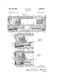
- FIGURE 6 is a fragmentary longitudinal, top crosssectional view of the door closer of FIGURE l during the latching speed stage;
- FIGURE 7 is a fragmentary longitudinal, top crosssectional view of the door closer of FIGURE 1 which has been adjusted for a quick release stage, the door closer being illustrated during this stage.
- the door closer of the present invention is indicated generally by reference numeral 20.
- the door closer is operatively connected to a door suitably hinged to a door frame (not shown). It is the function of the door closer 20 to control the speed and ease with which the door is opened and closed. Furthermore, the door closer 20 functions to assure that the door properly latches, without slamming, into the door frame. In this connection the door closer 20 permits the door to open at a relatively rapid rate in response to a person pushing or pulling the door. This is hereinafter referred to as the initial door-opening stage.
- the door closer 20 is adapted to increase the amount of force necessary to open the door past this predetermined arc and to reduce the opening speed of the door during this back check stage.
- the door closer 20 allows the door to close at a rapid or slow speed, as desired, until it has returned relatively close to the door frame.
- This stage is hereinafter referred to as the general speed stage.
- the door goes through the nal stage of its closing operation in which it latches in the door frame.
- the door closer 20 will assure that the door has suicient speed to properly latch, yet not enough speed to bang or slam into the door frame.
- the door closer 20 brakes the speed of the door to assure that it will not bang or slam into the door frame and yet properly latch, which is referred to hereinafter as the latching speed stage.
- the latching speed stage On the other hand, if the door closer 20 has been set so that during the general speed stage the door is closing very slowly, then the door closer 20 allows the door to speed up sufficiently to assure proper latching, which is hereinafter referred to as the quick release stage.
- the door closer 20 includes a main body 22, preferably of cast metal, contoured with grooves to provide anges 24 and 26 designed for sliding engagement endwise with the runs of a mounting bracket, such as shown in the U.S. Patent No. 2,723,416.
- the body 22 is installed by sliding it endwise into the bracket so that the weight of the door closer 20 is readily borne by the door or door frame to which the mounting bracket is attached.
- the door closer 20 is readily installed in this .manner in either its upright or inverted position, so that it is suitable for use on a right-hand door, a left-hand door or on the door frame associated with such a righthand or left-hand door.
- the door closer 20 may be arranged or mounted in a vertical direction for use in conjunction with sliding doors.
- the main body 22 is provided with a transverse bore 28. At its opposite ends, the bore 28 is formed with threaded terminals 30 and 32 into which journal sleeves 34 and 36, respectively, are tightly screwed.
- the sleeves 34 and 36 carry anti-friction bushings 38 and 40 within which the journal portions 42 and 44 of a driving spindle 46 are mounted.
- Suitable gaskets and packing rings are interposed to prevent leakage around the journal portions 42 and 44 of the driving spindle 46 and the journal sleeves 34 and 36.
- the journal portions 42 and 44 of the spindle 46 project beyond the sleeves 34 and 36.
- the spindle 46 is driven from one end only at a time although either end may be utilized alternatively.
- the journal ends of the spindle 46 are nished with serrations 48 engageable with mating serrations in a hub of a driving arm, which is part of the cooperating linkage (not shown) between the door closer 20 and the door.
- the end of the spindle 46 not in use at any one time may be closed by a cap (not shown).
- a longitudinal, circular cylindrical bore or piston chamber 52 Within the main body y22 and partially intersecting the transverse bore 28 is a longitudinal, circular cylindrical bore or piston chamber 52.
- the piston chamber ⁇ 52 extends longitudinally through the entire main body 22.
- the opposite ends of the piston chamber 52 are closed by identical plugs 54 and' 56 threaded into position and conning suitable sealing rings (not shown) to prevent leakage.
- Operatively positioned within the Piston charnber 52 is a piston 58 having a piston head 60V and an annular piston skirt 62, one end of which is attached to the piston head 60.
- the annular piston skirt 62 forms a 'cavity 64 opening at the free end of the piston skirt 62 to the piston chamber 52.
- Adjacent the free end of the piston skirt 62 is an annular ridge 63 which, like the piston head 60, is in uid tight engagement with the wall of the piston chamber 52.
- the piston skirt 62, the piston head 60, the ridge 63 and the body 22 form an annular zone 65 within the piston chamber 52.
- the piston head i60 has a longitudinally extending piston head passageway 162, one end of which communitcates with the piston chamber ⁇ 52 and the other end communicates with the cavity 64.
- Opposing one-way ball valves or check valves 98 and 100 are positioned within the passageway :102.
- the check valve ⁇ 98 prevents flu-id from entering the passageway 102 from the cavity 64, but allows fluid to flow into the cavity 64 from the passageway 102.
- the check valve 100 prevents fluid from entering the passageway 102 from the piston chamber 52, but allows iluid to ow into the piston chamber y52 from the passageway 102.
- the piston head ⁇ 60 also contains a radially extending passageway 104 which communicates with the piston head passageway 102 between the check valves 98 and 100.
- One end of the passageway 104 communicates with the annular zone 65 and the bore 28. The other end of the passageway 104 is blocked oit by the main body 22 when the piston head '60 is lin the piston chamber r52.
- a helically coiled compression spring 68 Normally the piston 58 is urged toward one extreme position 4by a helically coiled compression spring 68.
- the spring 68 bears at one end on the plug 54, passes through the cavity 64 and at the other end bears against the piston head 60.
- the .spring 68 has sufficient strength to urge vthe door toward the closed position against all ordinary forces which tend to oppose such closing movement.
- the cooperating linkage (not shown) between the door and the door closer 20 is such that the pinion 50 is rotated in a clockwise direction and the piston 58 is moved ⁇ toward the right (when viewing yFIGURE l), the spring 68 being compressed.
- the spring 68 elects door closing and is suiciently forceful to move ⁇ the door -to a closed latched position in the door frame.
- a body of hydraulic fluid such as oil or an oil substitute, is ydisposed within the piston chamber ⁇ 52.
- the oil lies within the variable chambers at opposite ends of the piston chamber 52 partly bounded by the interposed piston 58. Only through the valving arrangement to be described may the fluid flow directly from the piston chamber 52 into the bore 28.
- ⁇ Communicating with the far 4right of ⁇ the piston chamber 52 is a passageway 70 leading to a by-pass passageway 72 communicating with the bore 28. Also communicating with the piston chamber 52 and the by-pass passageway 72 is a passageway 74.
- the passageway 74 communicates with the piston chamber 512 at a point spaced longitudinally from the point at which the passageway 70 communicates with the piston chamber 52.
- the passageway 74 communicates ⁇ with the bypass passageway 72 at a point spaced longitudinally from the point at which the passageway 7 0 communicates with the by-pass passageway 72.
- 4Sealing off one end of the by-pass passageway l72 is an adjustable needle valve or fthe like ⁇ 76 threadly engaging the main body 22.
- the needle valve 76 forms with the by-pass passageway 72 a restricted variable orifice 78 located between the points where passageways 74 and 70 communicate with the bypass passageway 72.
- the needle valve 76 may be rotated to increase or decrease the size of the perennial 78 and thereby adjust the opening of the door in a manner more apparent hereinafter.
- valves may be employed for the adjustable Anlagen 78 in the bypass passageway 72.
- the particular valve utilized forms no part of the present invention, its selection being a matter within the skill of one in the art.
- a passageway 84 is also communicating with the piston chamber 52 and the by-pass passageway 82.
- a sleeve member 86 is positioned within the by-pass passageway 82 and has a radial hole 88 communicating with the passageway 80 and a radial 'hole 90 communicating with the passageway 84. Sealing off one end of the by-pass passageway 82 is an adjustable dual needle valve or the like 92 threadedly engaging the main body 22.
- the needle valve 92 has a plurality of longitudinal slots 94, one of which communicates with the radial hole 88 to form, with the sleeve 86, a variable orifice in the by-pass passageway 82 lbetween the passageway 80 and an annular zone communicating with the passageway 84.
- the needle valve 92 forms with the sleeve 86 -a restricted, variable orifice 96 positioned between where the passageway 84 communicates with the by-pass passageway 82 and where the by-pass passageway 82 communicates with the bore 28.
- Both dutiess may be independently increased or decreased in size by proper rotation of the needle valve 92.
- the orilice formed by the slot 94 has been adjusted to be smaller than the oriiice 96. It will be understood that any valve means may be employed for these restricted orifices and that the particular valve means employed for these horri, part ofthe present invention.
- the door closer 20 is illustrated in FIGURES 1-3 at rest; that is, when the door is closed.
- the spindle 46 and pinion 50 ⁇ are rotated in a clockwise direction when viewing FIGURE l, thereby translating the piston 58 toward the right against the force exerted by the spring 68.
- the check valve 98 will be forced into its closed position and fluid will be forced from the piston chamber 52 into the passageway 74, the by-pass passageway 72 and the bore 28. From the bore 28 the fluid flows into the lannular zone 65 between the housing 22 and the piston skirt 62 and there enters the radial passageway 104.
- the iluid passes through the piston head passageway 102 and the check valve 100 into the piston chamber 52 on the trailing end of the piston 58.
- the iiuid forced from the piston chamber 52 takes, of course, the path of least resistance through the valving arrangement in the body 22. lFor this reason little fluid will pass through the passageway 70 and orifice 78 to the other, or trailing, end of piston 58, since the orifice 78 places a restriction upon the ⁇ flow path which does not exist if the fluid fiows through the passageway 74 in the manner described.
- FIGURE 4 illustrates the position of the piston 58 during the back check stage and the .arrows in FIGURE 4 indicate the iiow path of the iiuid during this stage. Since the passageway 74 has been blocked off by the ridge 63, the fluid must pass through the passageway 70, the by-pass passageway 72 and the restricted oriiice '78 into the bore 28. The fluid enters the annular Zone 65 and -flows through the passageways 104 and 102 and the check valve 100 to the trailing end of the piston 58.
- FIGURE 5 illustrates the general speed stage; that is, the stage in which the piston 58 moves toward the left 'but prior to its blocking ofi the passageway 84.
- the arrows in FIGURE 5 indicate the main flow path of the iiuid during this stage.
- the check valve 100 closes and iiuid will be forced through the passageway 84, the annular zone 95 between the sleeve 86 and the needle valve 92 and the restricted orifice 96, into the by-pass passageway 82.
- the fluid then flows into the bore 28 around the pinion 50 into the annular zone 65 around the piston skirt ⁇ 62 where it enters the passageway 104 in the piston head 60.
- the fluid leaves the piston head 60 through the passageway 102 and the check valve 98 and enters the piston cavity 64 on the trailing end of the piston head 60.
- iiuid may iiow from the cylindrical bore 28 through the by-pass passageway 72 to passageway 74 and there enter the piston chamber 52 on the trailing end of the piston 58, however, this pat-h is generally of greater resistance than the main flow path described herei'nbefore and thus will not carry the bulk of the iiuid being bypassed around the piston head 60.
- FIGURE 6 illustrates the position of the piston 58 and the ⁇ arrows in this figure indicate the ow of fluid in the door closer 20 during the latching speed stage.
- the latching speed stage continues when the piston head 60 moves past the passageway 84 and terminates when the door is securely latched in the door frame.
- the door closer 20 may be adjusted to achieve, among other things, a slow closing speed during the general speed stage such that it is necessary to increase the speed of the door just before it reaches the door frame to assure proper latching, i.e., a quick release stage.
- This modification is achieved by adjusting needle Vlalve 92 to make the orifice 96 smaller than the orifice formed by the slots 94. This has no effect on the initial door-opening stage and back check stage discussed hereinbefore.
- the perennial speed stage continues until the piston head 60 has moved past the passageway 84 as illustrated in FIGURE 7.
- a door closer including a body having a cylindrical piston chamber, a piston in said piston chamber, spring means for urging said piston along said piston chamber in one direction, said piston having a piston head with two sides, said piston head forming first and second chambers in said piston chamber, said piston including means forming a third chamber 'in said piston chamber, said piston head having a longitudinal passageway extending from one of said sides to the other of said sides, first and second one-way valves in said passageway in opposing relationship, said piston having a second passageway therein having one end communicating with said third chamber and another end communicating with said longitudinal passageway between said first and second valves, and a valving arrangement within said body whereby fluid forced from said piston chamber by one side of said piston head passes to said piston chamber on the other side of the piston head when the piston head is moving in said piston chamber in either direction.
- a door closer including a body having a cylindrical piston chamber, a piston in said piston chamber, a spring means for urging said piston along said piston chamber in one direction, said piston having a piston head with two sides, said piston head forming first and second chambers in said piston chamber, said piston including means forming a third chamber in said piston chamber, said piston head having a longitudinal passageway extending from one of said sides to the other of said sides, first and second one-way valves in said passageway in opposing relationship, said piston having a second passageway therein having one end communicating with said third chamber and another end communicating with said longitudinal passageway between said first and second valves, and a valving arrangement within said body whereby fiuid forced from said piston chamber by one side of said piston head passes to said piston chamber on the other ⁇ side of said piston head when the piston is moving in said piston chamber in either direction, said valving arrangement including first and second passageways in said body communicating with one end of said piston chamber, said first and second passageways being spaced from one another along the longitudinal axis of
- third and fourth passageways in said body communicate with the other end of said piston chamber, said third and fourth passageways being spaced from one another along the longitudinal axis of said piston chamber, said third and fourth passageways communicating with a second by-pass passageway, said second by-pass passageway communicating with said third chamber, a first valve in said second by-pass passageway between where said third and fourth passageways communicate with said second bypass passageway, and a second valve in said second bypass passageway between where said fourth passageway communicates with said second by-pass passageway and said second by-pass passageway communicates with said piston chamber.
- a door closer including a body having a cylindrical piston chamber, a piston in said piston chamber, said piston having a piston head and an annular piston skirt, one end of said piston skirt being connected to said piston head, the other end of said piston skirt having a ridge which is in substantially fluid tight engagement with said piston chamber, spring means for urging said piston along said piston chamber in one direction, said piston head having a longitudinally extending passageway therethrough, said passageway having first and second one-way valves in opposing relationship, a second passageway in said piston head communicating with said longitudinal passageway in said piston head between said first and second one-way valves, said second passageway communicating with said piston chamber on the outside of said piston skirt, and a valving arrangement within said body whereby fiuid may pass from one side of said piston head to the other side of said piston head through said passageways in said piston head when said piston head is moving in said piston chamber.
- a door closer including a body having a cylindrical piston chamber, a piston in said piston chamber, said piston having a piston head and an annular piston skirt, oneend of said piston skirt being connected to said piston head, the other end of said piston skirt having a ridge which is in substantially fluid tight engagement with said piston chamber, spring means for urging said piston along said piston chamber in one direction, said piston head having a longitudinally extending passageway therethrough, said passageway having first and second one-way valves in opposing relationship, a second passageway in said piston head communicating with said longitudinal passageway in said piston head between said first and second one-way valves, said second passageway communicating with said piston chamber on the outside of said piston skirt, and a valving arrangement within said body whereby iiuid may pass from one side of said piston head to the other side of said piston head through said passageways in said piston head when said piston head is moving in said piston chamber, said valving arrangement including first and second passageways in said body communicating with one end of said piston chamber, said first and second passageways being space
- third and fourth passageways in said body communicate with the other end of said piston chamber, said third and fourth passageways being spaced from one another along the longitudinal axis of said piston chamber, said third and fourth passageways communicating with a second by-pass passageway, said second by-pass passageway communicating with said piston chamber between said piston head and said ridge on said piston skirt, first and second valve in said second by-pass passageway, said first valve being positioned between where said third and fourth passageways communicate with said second by-pass passageway, and said second valve being positioned between where said fourth passageway communicates with said second by-pass passageway and said second by-pass passageway communicates with said piston chamber.
- a door closer comprising a body having a cylindrical piston chamber, a piston in said piston chamber, said piston having a piston head and an annular piston skirt, one end of said piston skirt being connected to said piston head, the other end of said piston skirt having a ridge which is in substantially fluid tight engagement with said piston chamber, said piston skirt having a gear rack, a transverse bore in said body communicating with said piston chamber between said piston head and said ridge of said piston skirt, a pinion shaft journalled in said bore, a gear on said pinion shaft meshing with said rack, spring means for urging said piston along said piston chamber in one direction, said piston head having a longitudinally extending passageway therethrough, said passageway having first and second one-way valves in opposing relationship, a second passageway in said piston head communicating with said longitudinally passageway in said piston head between said first and second one-way valves, said second passageway communicating with said piston chamber on the outside of said piston skirt, and a valving arrangement within said body whereby fluid may pass from one side of said piston head to the other
- a door closer comprising a body having a cylindrical piston chamber, a piston in said piston chamber, said piston having a piston head and an annular piston skirt, one end of said piston skirt being connected to said piston head, the other end of said piston skirt having a ridge which is in substantially fiuid tight engagement with said piston chamber, said piston skirt having a gear rack, a transverse bore in said body communicating with said piston chamber between said piston head and said ridge of said piston skirt, a pinion shaft journalled in said bore, a gear on said pinion shaft meshing with said rack, spring means for urging said piston along said piston chamber in one direction, said piston head having a longitudinally extending passageway therethrough, said passageway having first and second one-way valves in opposing relationship, a second passageway in said piston head communicating with said longitudinal passageway in said piston head between said first and second one-way valves, said second passageway communicating with said piston chamber on the outside of said piston skirt, and a valving arrangement within said body whereby fluid may pass from one side of said piston head to
- third and fourth passageways in said body communicate with the other end of said piston chamber, said third and fourth passageways being spaced from one another along the longitudinal axis of said piston chamber, said third and fourth passageways communicating with a second by-pass passageway, said second by-pass passageway communicating with said bore, first and second valve in said second by-pass passageway, said first valve being positioned between where said third and fourth passageways communicate with said second by-pass passageway, and said second valve between where said fourth passageway communicates with said second by-pass passageway and said second by-pass passageway communicates with said bore.
- a door closer including a body having a cylindrical piston chamber, a piston in said piston chamber, spring means for urging said piston in one direction in said piston chamber, said piston having a piston head forming first and second chambers in said piston chamber, said piston head having a first passageway communicating with said first and second chambers, first and second oneway valves in opposing relationship in said first passageway, said piston including means forming a third charnber in said piston chamber, said piston having a second passageway therein having one end communicating with said third chamber and another end communicating with said first passageway between said first and second oneway valves, said third chamber also communicating with said first and second chambers through a valve arrangement in said body member.
- said means forming a third chamber in said piston chamber is a piston skirt having one end attached to said piston head and another end having a ridge which is in substantially fluid tight engagement with said piston chamber, said valving arrangement including third and fourth passageways in said body communicating with said second chamber, said third and fourth passageways being spaced from one another along the longitudinal axis of said second chamber, said third and fourth passageways communicating with a by-pass passageway, said by-pass passageway communicating with said first chamber and said third chamber, a first valve means within said by-pass passageway positioned between where said third and fourth passageways communicate with said by-pass passageway.
- fifth and sixth passageways in said body communicate with said first chamber, said fifth and sixth passageways being spaced from one another along the longitudinal axis of said first chamber, said fifth and sixth passageways communicating with a second by-pass passageway, said second bypass passageway communicating with said third chamber, a second valve means in said second by-pass passageway between where said fifth and sixth passageways communicate with said second by-pass passageway, and a second valve means in said second by-pass passageway between where said sixth passageway communicates with said second by-pass passageway and said second by-pass passageway communicates with said third chamber.
Description
Nov. 30, 1965 R. c. FLINT 3,220,047
DOOR CLOSER Filed Jan. lO, 1962 2 Sheets-Sheet 2 6.6 @o -5 f@ ff @1f W00 f4 /03 l] Il' l /M l! f Aww W L93 gggigiggg "l I JNVENTOR.
312 (96 35 96 r9? 25 ??we @ZZ/2i,
United States Patent Office 3,226,01113 Patented Nov. so, 1965 3,220,047 DOOR CLOSER Russell C. Flint, Princeton, Ill., assiguor to Schlage Lock Company, San Francisco, Calif., a corporation of California Filed Jan. 10, 1962, Ser. No. 165,330 14 Claims. (Cl. 16-62) The invention relates to a door closer for controlling the movement of a door with respect to its door frame both in the opening direction and in the closing direction. More particularly, the invention relates to a door closer of the spring and iluid type which has a piston head and a cooperating check arrangement whereby the speed of the door operatively connected to the door closer is checked or retarded just before it reaches its limit of movement in the door-opening direction and, furthermore, the speed of the door in the door-closing direction is controlled to assure proper latching without the door slamming against the door frame.
It is an object of the present invention to provide a door closer of generally improved characteristics.
It is a further object of the present invention to provide a door closer that will rapidly propel a door towards its closed position while controlling the motion of the door throughout its closing and latching operation.
It is a further object of the present invention to provide a door closer effective to retard the movement of the door toward and near its extreme open position; that is, to provide a back check.
It is a further object of the present invention to provide a simplified means of iluid control for an adjustable back check in a door closer.
It is a further object of the present invention to provide a door closer that can be readily and economically manufactured.
The invention, both as to its organization and method of operation, taken with further objects and advantages thereof, will best be understood by reference to the following description taken in connection with the accompanying drawings, in which:
FIGURE l is a longitudinal, top cross-sectional View of a door closer constructed in accordance with the present invention;
FIGURE 2 is a cross-sectional View of the door closer of FIGURE 1 taken along line 2 2 of FIGURE l;
FIGURE 3 is an end view of the door closer of FIG- URE l taken along line 3 3 of FIGURE l;
FIGURE 4 is a longitudinal, top cross-sectional view of the door closer of FIGURE l during the back check stage;
FIGURE 5 is a longitudinal, top cross-sectional view of the door closer of FIGURE 1 during the general speed stage;
FIGURE 6 is a fragmentary longitudinal, top crosssectional view of the door closer of FIGURE l during the latching speed stage; and
FIGURE 7 is a fragmentary longitudinal, top crosssectional view of the door closer of FIGURE 1 which has been adjusted for a quick release stage, the door closer being illustrated during this stage.
Referring now to the drawings, and more particularly to FIGURES 1-3, the door closer of the present invention is indicated generally by reference numeral 20. The door closer is operatively connected to a door suitably hinged to a door frame (not shown). It is the function of the door closer 20 to control the speed and ease with which the door is opened and closed. Furthermore, the door closer 20 functions to assure that the door properly latches, without slamming, into the door frame. In this connection the door closer 20 permits the door to open at a relatively rapid rate in response to a person pushing or pulling the door. This is hereinafter referred to as the initial door-opening stage. However, once the door has swung through a controllable predetermined arc, such as about 70, the door enters the stage hereinafter referred to as the back check stage; that is, the door closer 20 is adapted to increase the amount of force necessary to open the door past this predetermined arc and to reduce the opening speed of the door during this back check stage.
Once the door has completed its opening operation, the door closer 20 allows the door to close at a rapid or slow speed, as desired, until it has returned relatively close to the door frame. This stage is hereinafter referred to as the general speed stage. After completing this stage, the door goes through the nal stage of its closing operation in which it latches in the door frame. During this final stage the door closer 20 will assure that the door has suicient speed to properly latch, yet not enough speed to bang or slam into the door frame. Thus if the door during the general speed stage has been closing at a rapid rate, the door closer 20, in effect, brakes the speed of the door to assure that it will not bang or slam into the door frame and yet properly latch, which is referred to hereinafter as the latching speed stage. On the other hand, if the door closer 20 has been set so that during the general speed stage the door is closing very slowly, then the door closer 20 allows the door to speed up sufficiently to assure proper latching, which is hereinafter referred to as the quick release stage.
To these ends the door closer 20 includes a main body 22, preferably of cast metal, contoured with grooves to provide anges 24 and 26 designed for sliding engagement endwise with the runs of a mounting bracket, such as shown in the U.S. Patent No. 2,723,416. The body 22 is installed by sliding it endwise into the bracket so that the weight of the door closer 20 is readily borne by the door or door frame to which the mounting bracket is attached. The door closer 20 is readily installed in this .manner in either its upright or inverted position, so that it is suitable for use on a right-hand door, a left-hand door or on the door frame associated with such a righthand or left-hand door. Furthermore, the door closer 20 may be arranged or mounted in a vertical direction for use in conjunction with sliding doors.
The main body 22 is provided with a transverse bore 28. At its opposite ends, the bore 28 is formed with threaded terminals 30 and 32 into which journal sleeves 34 and 36, respectively, are tightly screwed. The sleeves 34 and 36 carry anti-friction bushings 38 and 40 within which the journal portions 42 and 44 of a driving spindle 46 are mounted. Symmetrically disposed between the ends of the spindle 46, and preferably formed integrally therewith, is a pinion 50 having a full or a partial set of gear teeth' of a standard contour. Suitable gaskets and packing rings (not shown) are interposed to prevent leakage around the journal portions 42 and 44 of the driving spindle 46 and the journal sleeves 34 and 36. The journal portions 42 and 44 of the spindle 46 project beyond the sleeves 34 and 36. The spindle 46 is driven from one end only at a time although either end may be utilized alternatively. The journal ends of the spindle 46 are nished with serrations 48 engageable with mating serrations in a hub of a driving arm, which is part of the cooperating linkage (not shown) between the door closer 20 and the door. The end of the spindle 46 not in use at any one time may be closed by a cap (not shown).
In any of these several possible mountings discussed hereinbefore, when the door is opened the cooper-ating linkage between the door and the door closer 20 produces a rota-tion of the spindle 46 within and with respect to the :main body 22. This relative rotation of the spindle 46 is utilized to effect the desired closing and checking functions to be described in more detail hereinafter.
Within the main body y22 and partially intersecting the transverse bore 28 is a longitudinal, circular cylindrical bore or piston chamber 52. The piston chamber `52 extends longitudinally through the entire main body 22. The opposite ends of the piston chamber 52 are closed by identical plugs 54 and' 56 threaded into position and conning suitable sealing rings (not shown) to prevent leakage. Operatively positioned within the Piston charnber 52 is a piston 58 having a piston head 60V and an annular piston skirt 62, one end of which is attached to the piston head 60. The annular piston skirt 62 forms a 'cavity 64 opening at the free end of the piston skirt 62 to the piston chamber 52. Adjacent the free end of the piston skirt 62 is an annular ridge 63 which, like the piston head 60, is in uid tight engagement with the wall of the piston chamber 52. The piston skirt 62, the piston head 60, the ridge 63 and the body 22 form an annular zone 65 within the piston chamber 52.
Along one side of the piston skirt 62 Ithere is provided a plurality of gear teeth 66 constituting a rack in engagement with the pinion lSti, so that upon rotation of the pinion 50, the rack and the piston 58 are correspondingly reciprocated. Despite the motion of the piston `58, the annular zone 65 always communicates with the bore 28 so that the bore 28 and the annular zone 65 are isolated from the ends of the piston chamber 52, except for the communication therebetween alorded by the piston head 60.
The piston head i60 has a longitudinally extending piston head passageway 162, one end of which communitcates with the piston chamber `52 and the other end communicates with the cavity 64. Opposing one-way ball valves or check valves 98 and 100 are positioned within the passageway :102. The check valve `98 prevents flu-id from entering the passageway 102 from the cavity 64, but allows fluid to flow into the cavity 64 from the passageway 102. Likewise, the check valve 100 prevents fluid from entering the passageway 102 from the piston chamber 52, but allows iluid to ow into the piston chamber y52 from the passageway 102. The piston head `60 also contains a radially extending passageway 104 which communicates with the piston head passageway 102 between the check valves 98 and 100. One end of the passageway 104 communicates with the annular zone 65 and the bore 28. The other end of the passageway 104 is blocked oit by the main body 22 when the piston head '60 is lin the piston chamber r52.
Normally the piston 58 is urged toward one extreme position 4by a helically coiled compression spring 68. The spring 68 bears at one end on the plug 54, passes through the cavity 64 and at the other end bears against the piston head 60. The .spring 68 has sufficient strength to urge vthe door toward the closed position against all ordinary forces which tend to oppose such closing movement. However, when the door is opened, the cooperating linkage (not shown) between the door and the door closer 20 is such that the pinion 50 is rotated in a clockwise direction and the piston 58 is moved `toward the right (when viewing yFIGURE l), the spring 68 being compressed. When the door is released in the open position, the spring 68 elects door closing and is suiciently forceful to move `the door -to a closed latched position in the door frame.
In order to control the movement of the door in both its opening and closing directions, a body of hydraulic fluid, such as oil or an oil substitute, is ydisposed within the piston chamber `52. The oil lies within the variable chambers at opposite ends of the piston chamber 52 partly bounded by the interposed piston 58. Only through the valving arrangement to be described may the fluid flow directly from the piston chamber 52 into the bore 28.
`Communicating with the far 4right of `the piston chamber 52 is a passageway 70 leading to a by-pass passageway 72 communicating with the bore 28. Also communicating with the piston chamber 52 and the by-pass passageway 72 is a passageway 74. The passageway 74 communicates with the piston chamber 512 at a point spaced longitudinally from the point at which the passageway 70 communicates with the piston chamber 52. Likewise, the passageway 74 communicates `with the bypass passageway 72 at a point spaced longitudinally from the point at which the passageway 7 0 communicates with the by-pass passageway 72. 4Sealing off one end of the by-pass passageway l72 is an adjustable needle valve or fthe like `76 threadly engaging the main body 22. The needle valve 76 forms with the by-pass passageway 72 a restricted variable orifice 78 located between the points where passageways 74 and 70 communicate with the bypass passageway 72. The needle valve 76 may be rotated to increase or decrease the size of the orice 78 and thereby adjust the opening of the door in a manner more apparent hereinafter.
It will be understood that many types of valves may be employed for the adjustable orice 78 in the bypass passageway 72. The particular valve utilized forms no part of the present invention, its selection being a matter within the skill of one in the art.
Communicating with the far left end of the piston chamber `52 is a passageway 80 leading to a by-pass passageway 82 communicating with the bore 28. Also communicating with the piston chamber 52 and the by-pass passageway 82 is a passageway 84. The passageway 84 communicates with the piston chamber =52 at a point spaced longitudinally from the point at which the passageway communicates with the piston chamber `52. Llkewise, the passageway 84 communicates with the bypass passageway 82 at a point spaced longitudinally from the point at which the passageway 801 communicates with the by-pass passageway `82.
A sleeve member 86 is positioned within the by-pass passageway 82 and has a radial hole 88 communicating with the passageway 80 and a radial 'hole 90 communicating with the passageway 84. Sealing off one end of the by-pass passageway 82 is an adjustable dual needle valve or the like 92 threadedly engaging the main body 22. The needle valve 92 has a plurality of longitudinal slots 94, one of which communicates with the radial hole 88 to form, with the sleeve 86, a variable orifice in the by-pass passageway 82 lbetween the passageway 80 and an annular zone communicating with the passageway 84. In addition, the needle valve 92 forms with the sleeve 86 -a restricted, variable orifice 96 positioned between where the passageway 84 communicates with the by-pass passageway 82 and where the by-pass passageway 82 communicates with the bore 28. Both orices may be independently increased or decreased in size by proper rotation of the needle valve 92. In the embodiment illustrated the orilice formed by the slot 94 has been adjusted to be smaller than the oriiice 96. It will be understood that any valve means may be employed for these restricted orifices and that the particular valve means employed for these orices is not, per se, part ofthe present invention.
The door closer 20 is illustrated in FIGURES 1-3 at rest; that is, when the door is closed. When the door is opened the spindle 46 and pinion 50` are rotated in a clockwise direction when viewing FIGURE l, thereby translating the piston 58 toward the right against the force exerted by the spring 68. During the initial door-opening stage7 which ends when the ridge 63 of the piston skirt 62 closes oit the passageway 74, the check valve 98 will be forced into its closed position and fluid will be forced from the piston chamber 52 into the passageway 74, the by-pass passageway 72 and the bore 28. From the bore 28 the fluid flows into the lannular zone 65 between the housing 22 and the piston skirt 62 and there enters the radial passageway 104. The iluid passes through the piston head passageway 102 and the check valve 100 into the piston chamber 52 on the trailing end of the piston 58. The iiuid forced from the piston chamber 52 takes, of course, the path of least resistance through the valving arrangement in the body 22. lFor this reason little fluid will pass through the passageway 70 and orifice 78 to the other, or trailing, end of piston 58, since the orifice 78 places a restriction upon the `flow path which does not exist if the fluid fiows through the passageway 74 in the manner described.
The initial door-opening stage continues until the ridge 63 of the piston skirt 62 has closed ofi the passageway 74, as illustrated in FIGURE 4. At this point the door and door closer 20 enter the back check stage. FIGURE 4 illustrates the position of the piston 58 during the back check stage and the .arrows in FIGURE 4 indicate the iiow path of the iiuid during this stage. Since the passageway 74 has been blocked off by the ridge 63, the fluid must pass through the passageway 70, the by-pass passageway 72 and the restricted oriiice '78 into the bore 28. The fluid enters the annular Zone 65 and -flows through the passageways 104 and 102 and the check valve 100 to the trailing end of the piston 58. During this back check stage, the liuid flowing to the trailing end of the pist-on 58 must pass through the restricted orifice 78, which has the effect of reducing the speed of the opening door. |Furthermore, during the back check stage it will require more pressure than during the initial door opening stage to further open the door.
When the door is released in the open position it will begin its closing operation -by virtue of the spring 68 acting against the piston head 60 and urging the piston 58 toward the left. Movement of the piston 58 toward the left will cause rotation of the pinion 50 and the spindle 46 thereby causing the door to close by virtue of the cooperating arm linkage (not shown) between the door closer 20 and the door frame. FIGURE 5 illustrates the general speed stage; that is, the stage in which the piston 58 moves toward the left 'but prior to its blocking ofi the passageway 84. The arrows in FIGURE 5 indicate the main flow path of the iiuid during this stage. y
During the general speed stage, the check valve 100 closes and iiuid will be forced through the passageway 84, the annular zone 95 between the sleeve 86 and the needle valve 92 and the restricted orifice 96, into the by-pass passageway 82. The fluid then flows into the bore 28 around the pinion 50 into the annular zone 65 around the piston skirt `62 where it enters the passageway 104 in the piston head 60. The fluid leaves the piston head 60 through the passageway 102 and the check valve 98 and enters the piston cavity 64 on the trailing end of the piston head 60. Some iiuid may iiow from the cylindrical bore 28 through the by-pass passageway 72 to passageway 74 and there enter the piston chamber 52 on the trailing end of the piston 58, however, this pat-h is generally of greater resistance than the main flow path described herei'nbefore and thus will not carry the bulk of the iiuid being bypassed around the piston head 60.
When the piston 4head 60 has blocked off the passageway 84, the door enters the latching speed stage at which time the door is relatively close to the door frame. This is the stage in which the speed of t-he door is substantially reduced to prevent the door from slamming into the door frame. FIGURE 6 illustrates the position of the piston 58 and the `arrows in this figure indicate the ow of fluid in the door closer 20 during the latching speed stage.
During the latching speed stage the piston 58 moves toward the left and the check valve 100 is thereby closed. Fluid is forced from the piston chamber 52 through the passageway 80, the restricted orifice formed by the slot 94, the annular zone 95, the restricted orifice 96 and into the by-pass pasageway 82. From the by-pass passageway 82 the fiuid passes through the bore 28 and into the annular zone 65 around the piston skirt 62. The fluid passes through the radially extending passageway 104 into the piston head pasageway 102 and through the open check valve 98 into the cavity 64 formed by the piston skirt 62. There will be some iiow of liu-id through the by-pass passageway 72 and the passageway 74 for the reasons discussed hereinbefore with respect to the general speed stage. It will be understood that since the fluid displaced from the piston chamber 52 must, during the latching speed stage, flow through the orifice formed by the slots 94, which is more restricted in this instance than orifice 96, that the iiow of fluid is decreased substantially, thereby substantially reducing the speed of the closing door to insure latch-ing without slamming into the door frame.
The latching speed stage continues when the piston head 60 moves past the passageway 84 and terminates when the door is securely latched in the door frame.
The door closer 20 may be adjusted to achieve, among other things, a slow closing speed during the general speed stage such that it is necessary to increase the speed of the door just before it reaches the door frame to assure proper latching, i.e., a quick release stage. This modification is achieved by adjusting needle Vlalve 92 to make the orifice 96 smaller than the orifice formed by the slots 94. This has no effect on the initial door-opening stage and back check stage discussed hereinbefore. Now, however, during the genenal speed stage, though the ow path of the fluid is not altered, the orice `96 only permits the door to close slowly. In this instance, the general speed stage continues until the piston head 60 has moved past the passageway 84 as illustrated in FIGURE 7. Then the quick release stage begins, the flow of fiuid during this quick release stage being illustrated in FIGURE 7. Fluid forced from the piston chamber 52 passes through the passageway 80 and the restricted orifice formed by slot 94 into the annular zone 95. From the annular zone 95 the fluid passes through the hole into the passageway 84 where it flows into the annular zone 65 around the piston chamber 52. The iiuid passes through the piston head 60 via the passageway 104, the piston head passageway 102 and the check valve 98, to the cavity 64 :at the trail-ing end of the piston head 60. It will be understood that in this embodiment since the fluid need only fiow through the orifice formed by the slot 94 during the quick release stage the speed of the door will increase as compared to its speed during the general speed stage. In this manner, the door speeds up sufficiently during the quick release stage to assure proper latching. i While the embodiments described herein are at present considered to be preferred, it is understood that Various modifications and improvements may be made and it is intended to cover in the appended claims all such modifications and improvements as fall within the true spirit and scope of the invention.
What is desired to be claimed and secured by Letters Patent of the United States is:
1. In a door closer including a body having a cylindrical piston chamber, a piston in said piston chamber, spring means for urging said piston along said piston chamber in one direction, said piston having a piston head with two sides, said piston head forming first and second chambers in said piston chamber, said piston including means forming a third chamber 'in said piston chamber, said piston head having a longitudinal passageway extending from one of said sides to the other of said sides, first and second one-way valves in said passageway in opposing relationship, said piston having a second passageway therein having one end communicating with said third chamber and another end communicating with said longitudinal passageway between said first and second valves, and a valving arrangement within said body whereby fluid forced from said piston chamber by one side of said piston head passes to said piston chamber on the other side of the piston head when the piston head is moving in said piston chamber in either direction.
2. In the door closer of claim 1 wherein said uid forced from said piston chamber flows to said other side of said piston head through said longitudinal passageway in said piston head.
3. In a door closer including a body having a cylindrical piston chamber, a piston in said piston chamber, a spring means for urging said piston along said piston chamber in one direction, said piston having a piston head with two sides, said piston head forming first and second chambers in said piston chamber, said piston including means forming a third chamber in said piston chamber, said piston head having a longitudinal passageway extending from one of said sides to the other of said sides, first and second one-way valves in said passageway in opposing relationship, said piston having a second passageway therein having one end communicating with said third chamber and another end communicating with said longitudinal passageway between said first and second valves, and a valving arrangement within said body whereby fiuid forced from said piston chamber by one side of said piston head passes to said piston chamber on the other` side of said piston head when the piston is moving in said piston chamber in either direction, said valving arrangement including first and second passageways in said body communicating with one end of said piston chamber, said first and second passageways being spaced from one another along the longitudinal axis of the said piston chamber, said first and second passageways communicating with a by-pass passageway, said by-pass passageway communicating with said third chamber, a valve within said by-pass passageway positioned between where said first and second passageways communicate with said bypass passageway, whereby when one side of said piston is moved in a direction opposing the force of said spring fluid displaced from said piston chamber passes through said first passageway, said by-pass passageway and said longitudinal passageway to the other side of said piston head until said first passageway is closed by said piston, wherein fiuid displaced from said piston chamber passes through said second passageway, said valve, said by-pass passageway and said longitudinal passageway to the other side of said piston head.
4. In the door closer of claim 3 wherein third and fourth passageways in said body communicate with the other end of said piston chamber, said third and fourth passageways being spaced from one another along the longitudinal axis of said piston chamber, said third and fourth passageways communicating with a second by-pass passageway, said second by-pass passageway communicating with said third chamber, a first valve in said second by-pass passageway between where said third and fourth passageways communicate with said second bypass passageway, and a second valve in said second bypass passageway between where said fourth passageway communicates with said second by-pass passageway and said second by-pass passageway communicates with said piston chamber.
5. In a door closer including a body having a cylindrical piston chamber, a piston in said piston chamber, said piston having a piston head and an annular piston skirt, one end of said piston skirt being connected to said piston head, the other end of said piston skirt having a ridge which is in substantially fluid tight engagement with said piston chamber, spring means for urging said piston along said piston chamber in one direction, said piston head having a longitudinally extending passageway therethrough, said passageway having first and second one-way valves in opposing relationship, a second passageway in said piston head communicating with said longitudinal passageway in said piston head between said first and second one-way valves, said second passageway communicating with said piston chamber on the outside of said piston skirt, and a valving arrangement within said body whereby fiuid may pass from one side of said piston head to the other side of said piston head through said passageways in said piston head when said piston head is moving in said piston chamber.
6. In a door closer including a body having a cylindrical piston chamber, a piston in said piston chamber, said piston having a piston head and an annular piston skirt, oneend of said piston skirt being connected to said piston head, the other end of said piston skirt having a ridge which is in substantially fluid tight engagement with said piston chamber, spring means for urging said piston along said piston chamber in one direction, said piston head having a longitudinally extending passageway therethrough, said passageway having first and second one-way valves in opposing relationship, a second passageway in said piston head communicating with said longitudinal passageway in said piston head between said first and second one-way valves, said second passageway communicating with said piston chamber on the outside of said piston skirt, and a valving arrangement within said body whereby iiuid may pass from one side of said piston head to the other side of said piston head through said passageways in said piston head when said piston head is moving in said piston chamber, said valving arrangement including first and second passageways in said body communicating with one end of said piston chamber, said first and second passageways being spaced from one another along the longitudinal axis of said piston chamber, said first and second passageways communicating with a iirst by-pass passageway, said first by-pass passageway communicating with said piston chamber between said piston head and said ridge on said piston skirt, a first valve in said first by-pass passageway between where said first and second passageways communicate with said first by-pass passageway.
7. In the door closer of claim 6 wherein third and fourth passageways in said body communicate with the other end of said piston chamber, said third and fourth passageways being spaced from one another along the longitudinal axis of said piston chamber, said third and fourth passageways communicating with a second by-pass passageway, said second by-pass passageway communicating with said piston chamber between said piston head and said ridge on said piston skirt, first and second valve in said second by-pass passageway, said first valve being positioned between where said third and fourth passageways communicate with said second by-pass passageway, and said second valve being positioned between where said fourth passageway communicates with said second by-pass passageway and said second by-pass passageway communicates with said piston chamber.
8. A door closer comprising a body having a cylindrical piston chamber, a piston in said piston chamber, said piston having a piston head and an annular piston skirt, one end of said piston skirt being connected to said piston head, the other end of said piston skirt having a ridge which is in substantially fluid tight engagement with said piston chamber, said piston skirt having a gear rack, a transverse bore in said body communicating with said piston chamber between said piston head and said ridge of said piston skirt, a pinion shaft journalled in said bore, a gear on said pinion shaft meshing with said rack, spring means for urging said piston along said piston chamber in one direction, said piston head having a longitudinally extending passageway therethrough, said passageway having first and second one-way valves in opposing relationship, a second passageway in said piston head communicating with said longitudinally passageway in said piston head between said first and second one-way valves, said second passageway communicating with said piston chamber on the outside of said piston skirt, and a valving arrangement within said body whereby fluid may pass from one side of said piston head to the other side of said piston head through said passageways in said piston head when said piston head is moving in said piston chamber.
9. A door closer comprising a body having a cylindrical piston chamber, a piston in said piston chamber, said piston having a piston head and an annular piston skirt, one end of said piston skirt being connected to said piston head, the other end of said piston skirt having a ridge which is in substantially fiuid tight engagement with said piston chamber, said piston skirt having a gear rack, a transverse bore in said body communicating with said piston chamber between said piston head and said ridge of said piston skirt, a pinion shaft journalled in said bore, a gear on said pinion shaft meshing with said rack, spring means for urging said piston along said piston chamber in one direction, said piston head having a longitudinally extending passageway therethrough, said passageway having first and second one-way valves in opposing relationship, a second passageway in said piston head communicating with said longitudinal passageway in said piston head between said first and second one-way valves, said second passageway communicating with said piston chamber on the outside of said piston skirt, and a valving arrangement within said body whereby fluid may pass from one side of said piston head to the other side of said piston head through said passageway in said piston head when said piston head is moving in said piston chamber, said valving arrangement including first and second passageways in said body communicating with one end of said piston chamber, said first and second passageways being spaced from one another along the longitudinally axis of said piston chamber, said first and second passageways communicating with a first by-pass passageway, said first by-pass passageway communicating with said bore, a first valve in said first by-pass passageway between where said first and second passageways communicate with said first by-pass passageway.
10. The door closer of claim 9 wherein third and fourth passageways in said body communicate with the other end of said piston chamber, said third and fourth passageways being spaced from one another along the longitudinal axis of said piston chamber, said third and fourth passageways communicating with a second by-pass passageway, said second by-pass passageway communicating with said bore, first and second valve in said second by-pass passageway, said first valve being positioned between where said third and fourth passageways communicate with said second by-pass passageway, and said second valve between where said fourth passageway communicates with said second by-pass passageway and said second by-pass passageway communicates with said bore.
11. In a door closer including a body having a cylindrical piston chamber, a piston in said piston chamber, spring means for urging said piston in one direction in said piston chamber, said piston having a piston head forming first and second chambers in said piston chamber, said piston head having a first passageway communicating with said first and second chambers, first and second oneway valves in opposing relationship in said first passageway, said piston including means forming a third charnber in said piston chamber, said piston having a second passageway therein having one end communicating with said third chamber and another end communicating with said first passageway between said first and second oneway valves, said third chamber also communicating with said first and second chambers through a valve arrangement in said body member.
12. In the door closer of claim 11 wherein said means forming a third chamber in said piston chamber is a piston skirt having one end attached to said piston head and another end having a ridge which is in substantially fluid tight engagement with said piston chamber, said valving arrangement including third and fourth passageways in said body communicating with said second chamber, said third and fourth passageways being spaced from one another along the longitudinal axis of said second chamber, said third and fourth passageways communicating with a by-pass passageway, said by-pass passageway communicating with said first chamber and said third chamber, a first valve means within said by-pass passageway positioned between where said third and fourth passageways communicate with said by-pass passageway.
13. In the door closer of claim 12 wherein fifth and sixth passageways in said body communicate with said first chamber, said fifth and sixth passageways being spaced from one another along the longitudinal axis of said first chamber, said fifth and sixth passageways communicating with a second by-pass passageway, said second bypass passageway communicating with said third chamber, a second valve means in said second by-pass passageway between where said fifth and sixth passageways communicate with said second by-pass passageway, and a second valve means in said second by-pass passageway between where said sixth passageway communicates with said second by-pass passageway and said second by-pass passageway communicates with said third chamber.
14. In the door closer of claim 11 wherein movement of said piston in one direction causes fluid to be transferred from said second piston chamber to said first chamber through said valving arrangement, said third chamber and said first passageway, and movement of said piston in said other direction causes fluid to be displaced from said first chamber to said second chamber through said valving arrangement, said third chamber and said first passageway.
References Cited by the Examiner UNITED STATES PATENTS 1,521,682 1/1925 Gunn 18S- 88.8 1,786,782 12/1930 Shonnard 16-62 1,863,296 6/1932 Chryst 18S-88.7 2,087,350 7/1937 McCann l88-88.7 2,716,995 9/1955 Baugh et al 137-506 2,790,991 5/ 1957 Schlage 16-62 DONLEY I. STOCKING, Primary Examiner,
Claims (1)
1. IN A DOOR CLOSER INCLUDING A BODY HAVING A CYLINDRICAL PISTON CHAMBER, A PISTON IN SAID PISTON CHAMBER, SPRING MEANS FOR URGING SAID PISTON ALONG SAID PISTON CHAMBER IN ONE DIRECTION, SAID PISTON HAVING A PISTON HEAD WITH TWO SIDES, SAID PISTON HEAD FORMING FIRST AND SECOND CHAMBERS IN SAID PISTON CHAMBER, SAID PISTON INCLUDING MEANS FORMING A THIRD CHAMBER IN SAID PISTON CHAMBER, SAID PISTON HEAD HAVING A LONGITUDINAL PASSAGEWAY EXTENDING FROM ONE OF SAID SIDES TO THE OTHER OF SAID SIDES, FIRST AND SECOND ONE-WAY VALVES IN SAID PASSAGEWAY IN OPPOSING RELATIONSHIP, SAID PISTON HAVING A
Priority Applications (1)
| Application Number | Priority Date | Filing Date | Title |
|---|---|---|---|
| US165330A US3220047A (en) | 1962-01-10 | 1962-01-10 | Door closer |
Applications Claiming Priority (1)
| Application Number | Priority Date | Filing Date | Title |
|---|---|---|---|
| US165330A US3220047A (en) | 1962-01-10 | 1962-01-10 | Door closer |
Publications (1)
| Publication Number | Publication Date |
|---|---|
| US3220047A true US3220047A (en) | 1965-11-30 |
Family
ID=22598463
Family Applications (1)
| Application Number | Title | Priority Date | Filing Date |
|---|---|---|---|
| US165330A Expired - Lifetime US3220047A (en) | 1962-01-10 | 1962-01-10 | Door closer |
Country Status (1)
| Country | Link |
|---|---|
| US (1) | US3220047A (en) |
Cited By (15)
| Publication number | Priority date | Publication date | Assignee | Title |
|---|---|---|---|---|
| DE2541790A1 (en) * | 1975-09-19 | 1977-03-24 | Dorma Baubeschlag | AUTOMATIC DOOR CLOSER |
| US4378612A (en) * | 1981-03-16 | 1983-04-05 | Schlage Lock Company | Door closer delayed action speed control system |
| US4414703A (en) * | 1981-09-01 | 1983-11-15 | Schlage Lock Company | Door closer and holder |
| US4665583A (en) * | 1984-09-28 | 1987-05-19 | Emhart Industries, Inc. | Door closer piston assembly having separate head portions |
| US4744125A (en) * | 1985-07-05 | 1988-05-17 | Geze Gmbh | Door closer transmission including an eccentric pinion |
| US4763385A (en) * | 1985-07-05 | 1988-08-16 | Geze Gmbh | Door closure transmission utilizing an eccentric pinion |
| US5259090A (en) * | 1991-07-31 | 1993-11-09 | Emhart Inc | Fluid door closer with means to permit entrapped gases to move |
| EP0606168A1 (en) * | 1993-01-08 | 1994-07-13 | Corbin Russwin, Inc. | Door closer |
| DE10107050A1 (en) * | 2001-02-13 | 2002-09-12 | Dorma Gmbh & Co Kg | Hydraulic swing leaf drive |
| DE10107046A1 (en) * | 2001-02-13 | 2002-09-12 | Dorma Gmbh & Co Kg | slide rail |
| DE10107051A1 (en) * | 2001-02-13 | 2002-09-12 | Dorma Gmbh & Co Kg | Electromechanical swing leaf drive |
| US20060237274A1 (en) * | 2005-03-30 | 2006-10-26 | Hsia Chun M | Shock absorbing device for cycle |
| US8225458B1 (en) | 2001-07-13 | 2012-07-24 | Hoffberg Steven M | Intelligent door restraint |
| US20180298665A1 (en) * | 2015-10-06 | 2018-10-18 | Oscar RODRIGUEZ RODRIGUEZ | Hidden closing door system |
| GB2580013A (en) * | 2018-09-28 | 2020-07-15 | Assa Abloy Ltd | Door-closer with overload valve |
Citations (6)
| Publication number | Priority date | Publication date | Assignee | Title |
|---|---|---|---|---|
| US1521682A (en) * | 1921-08-12 | 1925-01-06 | Packard Motor Car Co | Motor vehicle |
| US1786782A (en) * | 1925-11-02 | 1930-12-30 | Elevator Supplies Co Inc | Automatic door closer |
| US1863296A (en) * | 1930-06-18 | 1932-06-14 | Delco Prod Corp | Shock absorber |
| US2087350A (en) * | 1936-02-03 | 1937-07-20 | Gen Motors Corp | Shock absorber |
| US2716995A (en) * | 1950-09-23 | 1955-09-06 | Gen Motors Corp | Valve for reversible fluid pump |
| US2790991A (en) * | 1952-12-09 | 1957-05-07 | Schlage Lock Co | Door closer and check |
-
1962
- 1962-01-10 US US165330A patent/US3220047A/en not_active Expired - Lifetime
Patent Citations (6)
| Publication number | Priority date | Publication date | Assignee | Title |
|---|---|---|---|---|
| US1521682A (en) * | 1921-08-12 | 1925-01-06 | Packard Motor Car Co | Motor vehicle |
| US1786782A (en) * | 1925-11-02 | 1930-12-30 | Elevator Supplies Co Inc | Automatic door closer |
| US1863296A (en) * | 1930-06-18 | 1932-06-14 | Delco Prod Corp | Shock absorber |
| US2087350A (en) * | 1936-02-03 | 1937-07-20 | Gen Motors Corp | Shock absorber |
| US2716995A (en) * | 1950-09-23 | 1955-09-06 | Gen Motors Corp | Valve for reversible fluid pump |
| US2790991A (en) * | 1952-12-09 | 1957-05-07 | Schlage Lock Co | Door closer and check |
Cited By (25)
| Publication number | Priority date | Publication date | Assignee | Title |
|---|---|---|---|---|
| DE2541790A1 (en) * | 1975-09-19 | 1977-03-24 | Dorma Baubeschlag | AUTOMATIC DOOR CLOSER |
| US4378612A (en) * | 1981-03-16 | 1983-04-05 | Schlage Lock Company | Door closer delayed action speed control system |
| US4414703A (en) * | 1981-09-01 | 1983-11-15 | Schlage Lock Company | Door closer and holder |
| US4665583A (en) * | 1984-09-28 | 1987-05-19 | Emhart Industries, Inc. | Door closer piston assembly having separate head portions |
| US4744125A (en) * | 1985-07-05 | 1988-05-17 | Geze Gmbh | Door closer transmission including an eccentric pinion |
| US4763385A (en) * | 1985-07-05 | 1988-08-16 | Geze Gmbh | Door closure transmission utilizing an eccentric pinion |
| US5259090A (en) * | 1991-07-31 | 1993-11-09 | Emhart Inc | Fluid door closer with means to permit entrapped gases to move |
| EP0606168A1 (en) * | 1993-01-08 | 1994-07-13 | Corbin Russwin, Inc. | Door closer |
| AU666058B2 (en) * | 1993-01-08 | 1996-01-25 | Corbin Russwin Inc. | Door closer |
| DE10107046C2 (en) * | 2001-02-13 | 2003-05-28 | Dorma Gmbh & Co Kg | slide rail |
| US7024725B2 (en) * | 2001-02-13 | 2006-04-11 | Dorma Gmbh + Co. Kg | Overhead door closer with slide arm assembly |
| DE10107051A1 (en) * | 2001-02-13 | 2002-09-12 | Dorma Gmbh & Co Kg | Electromechanical swing leaf drive |
| DE10107050A1 (en) * | 2001-02-13 | 2002-09-12 | Dorma Gmbh & Co Kg | Hydraulic swing leaf drive |
| DE10107051C2 (en) * | 2001-02-13 | 2003-06-26 | Dorma Gmbh & Co Kg | Electromechanical swing leaf drive |
| DE10107050C2 (en) * | 2001-02-13 | 2003-07-03 | Dorma Gmbh & Co Kg | Hydraulic swing leaf drive |
| US20040074145A1 (en) * | 2001-02-13 | 2004-04-22 | Jurgen Homberg | Sliding rail door-closing device |
| DE10107046A1 (en) * | 2001-02-13 | 2002-09-12 | Dorma Gmbh & Co Kg | slide rail |
| US8225458B1 (en) | 2001-07-13 | 2012-07-24 | Hoffberg Steven M | Intelligent door restraint |
| US9121217B1 (en) | 2001-07-13 | 2015-09-01 | Steven M. Hoffberg | Intelligent door restraint |
| US9995076B1 (en) | 2001-07-13 | 2018-06-12 | Steven M. Hoffberg | Intelligent door restraint |
| US11187022B1 (en) | 2001-07-13 | 2021-11-30 | Steven M. Hoffberg | Intelligent door restraint |
| US20060237274A1 (en) * | 2005-03-30 | 2006-10-26 | Hsia Chun M | Shock absorbing device for cycle |
| US20180298665A1 (en) * | 2015-10-06 | 2018-10-18 | Oscar RODRIGUEZ RODRIGUEZ | Hidden closing door system |
| GB2580013A (en) * | 2018-09-28 | 2020-07-15 | Assa Abloy Ltd | Door-closer with overload valve |
| GB2580013B (en) * | 2018-09-28 | 2023-05-17 | Assa Abloy Ltd | Door-closer with overload valve |
Similar Documents
| Publication | Publication Date | Title |
|---|---|---|
| US3220047A (en) | Door closer | |
| US4349939A (en) | Automatic door closer | |
| US4115897A (en) | Zero force hold open door closer | |
| US3255482A (en) | Door closer | |
| GB1414851A (en) | Door check mechanisms | |
| US2490258A (en) | Hydraulically controlled hinge | |
| US2994906A (en) | Door closer with expansion chamber | |
| US2586135A (en) | Door closer | |
| US2763888A (en) | Door-closing mechanism | |
| US5272787A (en) | Overhead concealed door closer, mechanically, hydraulically operated | |
| US4386446A (en) | Door closer | |
| US3040372A (en) | Door closer mechanism | |
| US3156001A (en) | Closer with hold-open pivot arm | |
| US1770250A (en) | Control means for door closers | |
| US2723416A (en) | Door check and closer | |
| US4502180A (en) | Door control device having piston assembly with separately formed rack | |
| US2434524A (en) | Door checking hinge | |
| US2528904A (en) | Closing device for doors | |
| US2735132A (en) | Wartian | |
| US2790991A (en) | Door closer and check | |
| US3396424A (en) | Door closer | |
| GB1497220A (en) | Door closer | |
| FI52491B (en) | ||
| US2680263A (en) | Double-acting door check and combination | |
| US2701383A (en) | Door closer |