US3118564A - Separating helical springs - Google Patents
Separating helical springs Download PDFInfo
- Publication number
- US3118564A US3118564A US98613A US9861361A US3118564A US 3118564 A US3118564 A US 3118564A US 98613 A US98613 A US 98613A US 9861361 A US9861361 A US 9861361A US 3118564 A US3118564 A US 3118564A
- Authority
- US
- United States
- Prior art keywords
- springs
- coil
- mass
- entangled
- separating
- Prior art date
- Legal status (The legal status is an assumption and is not a legal conclusion. Google has not performed a legal analysis and makes no representation as to the accuracy of the status listed.)
- Expired - Lifetime
Links
Images

Classifications
-
- B—PERFORMING OPERATIONS; TRANSPORTING
- B65—CONVEYING; PACKING; STORING; HANDLING THIN OR FILAMENTARY MATERIAL
- B65G—TRANSPORT OR STORAGE DEVICES, e.g. CONVEYORS FOR LOADING OR TIPPING, SHOP CONVEYOR SYSTEMS OR PNEUMATIC TUBE CONVEYORS
- B65G47/00—Article or material-handling devices associated with conveyors; Methods employing such devices
- B65G47/02—Devices for feeding articles or materials to conveyors
- B65G47/04—Devices for feeding articles or materials to conveyors for feeding articles
- B65G47/12—Devices for feeding articles or materials to conveyors for feeding articles from disorderly-arranged article piles or from loose assemblages of articles
- B65G47/14—Devices for feeding articles or materials to conveyors for feeding articles from disorderly-arranged article piles or from loose assemblages of articles arranging or orientating the articles by mechanical or pneumatic means during feeding
- B65G47/1407—Devices for feeding articles or materials to conveyors for feeding articles from disorderly-arranged article piles or from loose assemblages of articles arranging or orientating the articles by mechanical or pneumatic means during feeding the articles being fed from a container, e.g. a bowl
-
- Y—GENERAL TAGGING OF NEW TECHNOLOGICAL DEVELOPMENTS; GENERAL TAGGING OF CROSS-SECTIONAL TECHNOLOGIES SPANNING OVER SEVERAL SECTIONS OF THE IPC; TECHNICAL SUBJECTS COVERED BY FORMER USPC CROSS-REFERENCE ART COLLECTIONS [XRACs] AND DIGESTS
- Y10—TECHNICAL SUBJECTS COVERED BY FORMER USPC
- Y10S—TECHNICAL SUBJECTS COVERED BY FORMER USPC CROSS-REFERENCE ART COLLECTIONS [XRACs] AND DIGESTS
- Y10S198/00—Conveyors: power-driven
- Y10S198/953—Coil spring untangling apparatus
Definitions
- the invention comprises laterally confining a mass of the loosely wound helical springs and periodically applying and removing a magnetic field to the mass.
- the periodic applying and removing of a magnetic field momentarily causes entangled springs to have a north and south pole.
- the ends of the two springs will both be north poles and south poles, respectively, so that they will repel one another tending to disentangle the springs.
- This combined with the slight agitation of the mass of springs causes the springs to become disentangled permitting them to be moved and passed outwardly by gravity from beneath the mass which is confined.
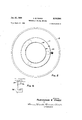
- FIG. 1 is a sectional elevational view of an apparatus embodying the invention.
- FIG. 2 is a fragmentary sectional view taken along the line 22 in FIG. 1.
- FIG. 3 is a view of entangled springs which are to be separated by the apparatus.
- FIG. 4 is a partly diagrammatic view showing adjacent disentangled springs.
- FIG. 5 is a planyiew of the apparatus shown in FIG. 1.
- PEG. 6 is a schematic diagram of an electrical circuit for the apparatus.
- the apparatus comprises a tube Ill of dielectric material such as plastic which has its upper and lower ends of open. Portions of the lower end of the tube it ⁇ are cut away as at 11 providing feet 12 that rest upon a plate 13 that is substantially flat and extends beyond the periphery of the tube 18.
- the plate 13 is made of a dielectric material such as plastic.
- the tube iii is confined on plate 13 by bosses 14 that are fixed to the legs 12 and screws 15 of non-magnetic material that extend through the bosses into projections 16 fixed to the plate 13.
- a magnetic coil 17 is provided around the lower end of the tube it ⁇ and is supported on an annular ring 18 of dielectric material such as plastic which is held in position on the tube by screws 19 of non-magnetic material.
- a clamp 21% is provided around the coil 17 to confine and hold the coil.
- each spring comprising a wire bent into helical form.
- the ends E are conventionally flat. Such springs have a tendency to become entangled With each other as shown in FIG. 3.
- a mass of the springs S is introduced into the open upper end of tube ill.
- the portions '11 that are cut away provide spaces 21 that have a height substantially equal to the diameter of the springs S so that any separated springs can roll laterally outwardly onto the periphery of plate 13 from which they can be removed or, alternatively, from which they can move along a chute to a machine for assembly with other parts.
- Means are provided for periodically applying electrical current to the coil 17. As shown in FIG. 6, this comprises a timer 25 that periodically energizes a solenoid 26 that opens and closes the switch 27 that supplies current to the coil. Although alternating current is preferred, direct current may also be applied.
- the mass of springs in tube id is such that the upper end of the mass is substantially above the upper end of the coil as shown at A in H6. 1 when the coil is not energized and yet not so great that it will not be lifted by the magnetic action of the coil 17.
- the mass is lifted upwardly to the position B shown in PEG. 1.
- the mass is permitted to fall downwardly.
- T he separation of the springs is achieved primarily by periodic magnetic field, supplemented by the slight agitating affect.
- the springs are momentarily magnetized so that one end of the combined springs is made a north pole and the other end is made a south pole. Since there are two distinct but entangled elements, the two ends of the springs that are adjacent one another and are north poles repel each other as do the opposite ends which are south poles. This causes the two springs to separate from one another. This combined with the slight agitation of the mass upwardly and downwardly causes a ready separation of the springs.
- an inclined rather than a fiat plate 13 can be provided on the lower end of the tube so that all the springs tend to collect in one area when they are separated from which area they can be manually removed or removed through chutes or other means.
- slots having a length and width substantially equal to the length and diameter of the springs can be provided in the plate 13 within the confines of the tube so that as the springs are separated and become aligned with the slots they will drop through the slots.
- a typical example of a satisfactory spring separator that has been used for separating springs made of steel and being approximately five-eighths of an inch in length and five-sixteenths of an inch in diameter has the following dimensions:
- an apparatus embodying the invention can be used for a very short period of time to separate a large quantity of springs for manufacturing operations.
- the method of separating wound helical springs and similar articles which may become entangled comprises providing a tree lateral path for at least one of said springs and periodically applying and removing a magnetic field to the entangled springs to create a north and south pole in said springs so that the entangled springs having identical poles at adjacent ends tend to repel one another thereby disentangling from one another by said one spring only moving along said path.
- the method of separating wound helical springs and similar articles which may become entangled which comprises laterally confining a mass of the springs but providing a free lateral path for at least one entangled spring, and periodically applying and removing a magnetic field to the laterally confined mass to project said spring along said path.
- the method of separating and dispensing wound helical springs and similar articles which may become entangled which comprises laterally confining a mass of the springs, providing a free path beneath said confined mass and laterally of at least one spring, periodically applying and removing a magnetic field to the laterally confined mass along said path, and permitting separated spnings to move laterally from beneath said confined mass during the periods when the magnetic field is not being applied.
- An apparatus for separating wound helical springs and similar articles which may become entangled which comprises means for laterally confining a mass of springs, means adjacent the lower end of said mass defining an opening through which disentangled springs may move, a coil surrounding said laterally confining means, and means for periodically energizing and dc-energizing said coil to periodically rnagnetize the mass of springs.
- An apparatus for separating wound helical springs and similar articles which may become entangled which comprises means for laterally confining a mass of the springs above a surface, means defining an opening whereby disentangled springs may move from said mass laterally outwardly onto and along said surface, a coil surrounding said laterally confining means, and means for periodically energizing and de-energizing said coil to periodically magnetize the mass of springs.
- An apparatus for separating and dispensing loosely wound helical springs and similar articles which may become entangled which comprises a wall of dielectric material defining a chamber, means adiacent the lower end of said wall defining a surface, said wall having portions thereof spaced from said surface to permit individual separated springs to move laterally from within the Wall to the exterior of the wall along said surface, a coil surrounding said wall, and means for periodically energizing said coil to create a periodic magnetic field within said wall.
- An apparatus for separating and dispensing loosely wound helical springs and similar articles which may become entangled with one another which apparatus comprises a tube of dielectric material, means defining a surface adjacent the lower end of the tube, said tube having portions thereof spaced from said surface a distance suffioient to permit individual springs to move laterally outwardly from within the confines of said tube along said surface, a coil around said tube, and means for periodically energizing said coil to create a periodic magnetic field within said tube.
- the method of separating and dispensing wound helical springs and similar articles which may become entangled comprises laterally confining a mass of the articles within a coil, providing a free path beneath said coil and laterally of an entangled spring, periodically applying and removing current to said coil, and permitting separated springs to move laterally along said path from beneath said coil during the periods when the current is not being supplied to said coil.
- An apparatus for separating and dispensing loosely wound helical springs and similar articles which may become entangled which comprises a wall of dielectric material defining a chamber, means on the lower end of said wall for holding said wall in spaced relation to a surface with relation to which said wall is positioned, so that individual separated articles may move lateral-1y from within the wall to the exterior of the wall along the surface, a coil surrounding said wall, and means for periodically energizing said coil to create a periodic magnetic field within said Wall.
Landscapes
- Engineering & Computer Science (AREA)
- Mechanical Engineering (AREA)
- Feeding Of Articles To Conveyors (AREA)
Description
Jan. 21, 1964 A. E. VOKES 3,118,564
SEPARATING HELICAL SPRINGS Filed March 27, 1961 2 Sheets-Sheet 1 ALEXANDER 6'. l/oKcs BY M f o'wa em ATTORNE. Y5
1964 A. E. VOKES 3,118,564
SEPARATING HELICAL SPRINGS Filed March 2'7, 1961 2 Sheets-Sheet 2 Z S TIMER INVENTOR. ALEXANDER E. VeI s ATTOR NE Y5 United States Patent @hlice 3,118,564 Patented Jan. 21, 1964 SEPARATING HELltJAL SPRINGS Alexander E. Volres, 17305 Forrer, Detroit 36, Mich. Filed Mar. 27, 1961, Ser. N 98,613 Claims. (Cl. 221-1) This invention relates to the handling of loosely wound helical springs and particularly to the separating of such helical springs which become entangled with one another.
In certain assembly operations of parts which utilize small loosely wound helical springs, a major problem exists in that when the mass of springs is handled, there is a tendency for the springs to become entangled with one another. It is customary to utilize workers and manually separate these springs in order that they can be fed to a machine for assembly purposes.
It is an object of this invention to provide a method and apparatus for separating helical springs which become entangled.
It is a further object of the invention to provide such an apparatus which is relatively inexpensive, simple in construction and requires a minimum of maintenance.
Basically, the invention comprises laterally confining a mass of the loosely wound helical springs and periodically applying and removing a magnetic field to the mass. The periodic applying and removing of a magnetic field momentarily causes entangled springs to have a north and south pole. When two springs are entangled, the ends of the two springs will both be north poles and south poles, respectively, so that they will repel one another tending to disentangle the springs. This combined with the slight agitation of the mass of springs causes the springs to become disentangled permitting them to be moved and passed outwardly by gravity from beneath the mass which is confined.
In the drawings:
FIG. 1 is a sectional elevational view of an apparatus embodying the invention.
FIG. 2 is a fragmentary sectional view taken along the line 22 in FIG. 1.
FIG. 3 is a view of entangled springs which are to be separated by the apparatus.
FIG. 4 is a partly diagrammatic view showing adjacent disentangled springs.
FIG. 5 is a planyiew of the apparatus shown in FIG. 1.
PEG. 6 is a schematic diagram of an electrical circuit for the apparatus.
Referring to FIGS. 1, 2 and 5, the apparatus comprises a tube Ill of dielectric material such as plastic which has its upper and lower ends of open. Portions of the lower end of the tube it} are cut away as at 11 providing feet 12 that rest upon a plate 13 that is substantially flat and extends beyond the periphery of the tube 18. The plate 13 is made of a dielectric material such as plastic.
As shown in HS. 2, the tube iii is confined on plate 13 by bosses 14 that are fixed to the legs 12 and screws 15 of non-magnetic material that extend through the bosses into projections 16 fixed to the plate 13.
A magnetic coil 17 is provided around the lower end of the tube it} and is supported on an annular ring 18 of dielectric material such as plastic which is held in position on the tube by screws 19 of non-magnetic material. A clamp 21% is provided around the coil 17 to confine and hold the coil.
The springs S which are to be separated are shown in FIG. 4, each spring comprising a wire bent into helical form. In springs of this type, the ends E are conventionally flat. Such springs have a tendency to become entangled With each other as shown in FIG. 3.
A mass of the springs S is introduced into the open upper end of tube ill. The portions '11 that are cut away provide spaces 21 that have a height substantially equal to the diameter of the springs S so that any separated springs can roll laterally outwardly onto the periphery of plate 13 from which they can be removed or, alternatively, from which they can move along a chute to a machine for assembly with other parts.
Means are provided for periodically applying electrical current to the coil 17. As shown in FIG. 6, this comprises a timer 25 that periodically energizes a solenoid 26 that opens and closes the switch 27 that supplies current to the coil. Although alternating current is preferred, direct current may also be applied.
The mass of springs in tube id is such that the upper end of the mass is substantially above the upper end of the coil as shown at A in H6. 1 when the coil is not energized and yet not so great that it will not be lifted by the magnetic action of the coil 17. When the coil is energized, the mass is lifted upwardly to the position B shown in PEG. 1. When the coil is again de-energized, the mass is permitted to fall downwardly.
The successive energization and de-energization of the coil causes the springs to be separated and the individual springs adjacent the lower end of the mass are then permitted to roll outwardly by the vibration of the overlying mass of springs through the spaces 21 onto the plate 13.
T he separation of the springs is achieved primarily by periodic magnetic field, supplemented by the slight agitating affect. Referring to FIG. 3, when two springs S are entangled as shown in FIG. 3 and the magnetic coil is energized, the springs are momentarily magnetized so that one end of the combined springs is made a north pole and the other end is made a south pole. Since there are two distinct but entangled elements, the two ends of the springs that are adjacent one another and are north poles repel each other as do the opposite ends which are south poles. This causes the two springs to separate from one another. This combined with the slight agitation of the mass upwardly and downwardly causes a ready separation of the springs.
It can be appreciated that an inclined rather than a fiat plate 13 can be provided on the lower end of the tube so that all the springs tend to collect in one area when they are separated from which area they can be manually removed or removed through chutes or other means.
Instead of providing openings adjacent the lower end of the tube ltl, slots having a length and width substantially equal to the length and diameter of the springs can be provided in the plate 13 within the confines of the tube so that as the springs are separated and become aligned with the slots they will drop through the slots.
A typical example of a satisfactory spring separator that has been used for separating springs made of steel and being approximately five-eighths of an inch in length and five-sixteenths of an inch in diameter has the following dimensions:
Inside diameter of coil 6 inches. Outside diameter of coil 8 inches. Number of turns 620.
ize of wire No. 17. Diameter of wire .649 with insulation. Height of coil 2 inches. Width of coil 1 inch. Diameter of tube 6 inches.
When a current of 230 volts is successively and periodically applied to such an arrangement for periods of one second on and three seconds off, the desired separation of the springs is achieved.
Eecause of the rapid separation of the springs, an apparatus embodying the invention can be used for a very short period of time to separate a large quantity of springs for manufacturing operations.
It can thus be seen that I have provided a method and apparatus for readily separating loosely wound helical springs which may become entangled with one another. The apparatus is relatively simple, inexpensive to construct and operate and requires a minimum of maintenance. As a result, substantial saving is made in labor.
I claim:
1. The method of separating wound helical springs and similar articles which may become entangled which comprises providing a tree lateral path for at least one of said springs and periodically applying and removing a magnetic field to the entangled springs to create a north and south pole in said springs so that the entangled springs having identical poles at adjacent ends tend to repel one another thereby disentangling from one another by said one spring only moving along said path.
2. The method of separating wound helical springs and similar articles which may become entangled which comprises laterally confining a mass of the springs but providing a free lateral path for at least one entangled spring, and periodically applying and removing a magnetic field to the laterally confined mass to project said spring along said path.
3. The method of separating and dispensing wound helical springs and similar articles which may become entangled which comprises laterally confining a mass of the springs, providing a free path beneath said confined mass and laterally of at least one spring, periodically applying and removing a magnetic field to the laterally confined mass along said path, and permitting separated spnings to move laterally from beneath said confined mass during the periods when the magnetic field is not being applied.
4. An apparatus for separating wound helical springs and similar articles which may become entangled which comprises means for laterally confining a mass of springs, means adjacent the lower end of said mass defining an opening through which disentangled springs may move, a coil surrounding said laterally confining means, and means for periodically energizing and dc-energizing said coil to periodically rnagnetize the mass of springs.
5. An apparatus for separating wound helical springs and similar articles which may become entangled which comprises means for laterally confining a mass of the springs above a surface, means defining an opening whereby disentangled springs may move from said mass laterally outwardly onto and along said surface, a coil surrounding said laterally confining means, and means for periodically energizing and de-energizing said coil to periodically magnetize the mass of springs.
6. An apparatus for separating and dispensing loosely wound helical springs and similar articles which may become entangled which comprises a wall of dielectric material defining a chamber, means adiacent the lower end of said wall defining a surface, said wall having portions thereof spaced from said surface to permit individual separated springs to move laterally from within the Wall to the exterior of the wall along said surface, a coil surrounding said wall, and means for periodically energizing said coil to create a periodic magnetic field within said wall.
7. An apparatus for separating and dispensing loosely wound helical springs and similar articles which may become entangled with one another, which apparatus comprises a tube of dielectric material, means defining a surface adjacent the lower end of the tube, said tube having portions thereof spaced from said surface a distance suffioient to permit individual springs to move laterally outwardly from within the confines of said tube along said surface, a coil around said tube, and means for periodically energizing said coil to create a periodic magnetic field within said tube.
8. The method of separating and dispensing wound helical springs and similar articles which may become entangled which comprises laterally confining a mass of the articles within a coil, providing a free path beneath said coil and laterally of an entangled spring, periodically applying and removing current to said coil, and permitting separated springs to move laterally along said path from beneath said coil during the periods when the current is not being supplied to said coil.
9. The method set forth in claim 8 wherein current is supplied to said coil for a period of about one second and is removed from said coil for a period of about three seconds.
10. An apparatus for separating and dispensing loosely wound helical springs and similar articles which may become entangled which comprises a wall of dielectric material defining a chamber, means on the lower end of said wall for holding said wall in spaced relation to a surface with relation to which said wall is positioned, so that individual separated articles may move lateral-1y from within the wall to the exterior of the wall along the surface, a coil surrounding said wall, and means for periodically energizing said coil to create a periodic magnetic field within said Wall.
References Cited in the file of this patent UNITED STATES PATENTS 2,581,042 Otto Jan. 1, 1952 2,820,632 'Fowler Jan. 21, 1958 2,999,687 Hommel Sept. '12, 1961
Claims (1)
1. THE METHOD OF SEPARATING WOUND HELICAL SPRINGS AND SIMILAR ARTICLES WHICH MAY BECOME ENTANGLED WHICH COMPRISES PROVIDING A FREE LATERAL PATH FOR AT LEAST ONE OF SAID SPRINGS AND PERIODICALLY APPLYING AND REMOVING A MAGNETIC FIELD TO THE ENTANGLED SPRINGS TO CREATE A NORTH AND SOUTH POLE IN SAID SPRINGS SO THAT THE ENTANGLED SPRINGS HAVING IDENTICAL POLES AT ADJACENT ENDS TEND TO REPEL ONE ANOTHER THEREBY DISENTANGLING FROM ONE ANOTHER BY SAID ONE SPRING ONLY MOVING ALONG SAID PATH.
Priority Applications (1)
| Application Number | Priority Date | Filing Date | Title |
|---|---|---|---|
| US98613A US3118564A (en) | 1961-03-27 | 1961-03-27 | Separating helical springs |
Applications Claiming Priority (1)
| Application Number | Priority Date | Filing Date | Title |
|---|---|---|---|
| US98613A US3118564A (en) | 1961-03-27 | 1961-03-27 | Separating helical springs |
Publications (1)
| Publication Number | Publication Date |
|---|---|
| US3118564A true US3118564A (en) | 1964-01-21 |
Family
ID=22270118
Family Applications (1)
| Application Number | Title | Priority Date | Filing Date |
|---|---|---|---|
| US98613A Expired - Lifetime US3118564A (en) | 1961-03-27 | 1961-03-27 | Separating helical springs |
Country Status (1)
| Country | Link |
|---|---|
| US (1) | US3118564A (en) |
Cited By (14)
| Publication number | Priority date | Publication date | Assignee | Title |
|---|---|---|---|---|
| US3341030A (en) * | 1965-03-29 | 1967-09-12 | Eugene L Engels | Method and apparatus for positioning and orientating articles |
| US3346305A (en) * | 1965-09-29 | 1967-10-10 | Tiros Plastics Corp | Spring untangler |
| US3625570A (en) * | 1968-09-24 | 1971-12-07 | Concentric Prod Res | Apparatus for dispensing workpieces |
| US3951305A (en) * | 1974-10-25 | 1976-04-20 | Gti Corporation | Magnetic feeder and method of feeding magnetic parts |
| US4035029A (en) * | 1974-10-16 | 1977-07-12 | Tekno-Detaljer Ab | Apparatus for separating entangled objects from each other, such as springs or other objects having a tendency to hitch to each other |
| EP0054669A1 (en) * | 1980-12-17 | 1982-06-30 | Siemens Aktiengesellschaft | Device for disentangling and feeding ferromagnetic helical springs from a loose mass |
| US4396108A (en) * | 1976-08-27 | 1983-08-02 | Walter Sticht | Apparatus for separating individual assembly parts from a coherent mass |
| US4480739A (en) * | 1980-01-22 | 1984-11-06 | Siemens Aktiengesellschaft | Method and apparatus for separating, ordering and feeding metallic workpieces |
| US20180056460A1 (en) * | 2016-08-31 | 2018-03-01 | InFocus Industrial System Limited | Spring separating and feeding device and method thereof |
| US20180141689A1 (en) * | 2015-07-18 | 2018-05-24 | Harro Hoefliger Verpackungsmaschinen Gmbh | Method and device for separating and transferring pellets |
| US20180359937A1 (en) * | 2017-06-14 | 2018-12-20 | Grow Solutions Tech Llc | Precision seeder heads and seeder components that include precision seeder heads |
| US20180359913A1 (en) * | 2017-06-14 | 2018-12-20 | Grow Solutions Tech Llc | Systems and Methods for Depositing Seeds in a Grow Pod |
| US20190016522A1 (en) * | 2015-06-01 | 2019-01-17 | Jason Littman | Selectively Changeable, Volumetric Dispensers And Methods of Dispensing Materials Having Known Unit Volumes |
| EP4345034A1 (en) * | 2022-09-30 | 2024-04-03 | Maurer Magnetic AG | Method of aligning wood screws and aligning apparatus therefor |
Citations (3)
| Publication number | Priority date | Publication date | Assignee | Title |
|---|---|---|---|---|
| US2581042A (en) * | 1946-08-17 | 1952-01-01 | Otto Stuart | Nail packaging machine |
| US2820632A (en) * | 1953-06-04 | 1958-01-21 | Fowler Alexander | De-magnetizer for magnetic feed system |
| US2999687A (en) * | 1958-12-23 | 1961-09-12 | American Can Co | Sheet feeder |
-
1961
- 1961-03-27 US US98613A patent/US3118564A/en not_active Expired - Lifetime
Patent Citations (3)
| Publication number | Priority date | Publication date | Assignee | Title |
|---|---|---|---|---|
| US2581042A (en) * | 1946-08-17 | 1952-01-01 | Otto Stuart | Nail packaging machine |
| US2820632A (en) * | 1953-06-04 | 1958-01-21 | Fowler Alexander | De-magnetizer for magnetic feed system |
| US2999687A (en) * | 1958-12-23 | 1961-09-12 | American Can Co | Sheet feeder |
Cited By (16)
| Publication number | Priority date | Publication date | Assignee | Title |
|---|---|---|---|---|
| US3341030A (en) * | 1965-03-29 | 1967-09-12 | Eugene L Engels | Method and apparatus for positioning and orientating articles |
| US3346305A (en) * | 1965-09-29 | 1967-10-10 | Tiros Plastics Corp | Spring untangler |
| US3625570A (en) * | 1968-09-24 | 1971-12-07 | Concentric Prod Res | Apparatus for dispensing workpieces |
| US4035029A (en) * | 1974-10-16 | 1977-07-12 | Tekno-Detaljer Ab | Apparatus for separating entangled objects from each other, such as springs or other objects having a tendency to hitch to each other |
| US3951305A (en) * | 1974-10-25 | 1976-04-20 | Gti Corporation | Magnetic feeder and method of feeding magnetic parts |
| US4396108A (en) * | 1976-08-27 | 1983-08-02 | Walter Sticht | Apparatus for separating individual assembly parts from a coherent mass |
| US4480739A (en) * | 1980-01-22 | 1984-11-06 | Siemens Aktiengesellschaft | Method and apparatus for separating, ordering and feeding metallic workpieces |
| EP0054669A1 (en) * | 1980-12-17 | 1982-06-30 | Siemens Aktiengesellschaft | Device for disentangling and feeding ferromagnetic helical springs from a loose mass |
| US20190016522A1 (en) * | 2015-06-01 | 2019-01-17 | Jason Littman | Selectively Changeable, Volumetric Dispensers And Methods of Dispensing Materials Having Known Unit Volumes |
| US20180141689A1 (en) * | 2015-07-18 | 2018-05-24 | Harro Hoefliger Verpackungsmaschinen Gmbh | Method and device for separating and transferring pellets |
| US10556712B2 (en) * | 2015-07-18 | 2020-02-11 | Harro Hoefliger Verpackungsmaschinen Gmbh | Method and device for separating and transferring pellets |
| US20180056460A1 (en) * | 2016-08-31 | 2018-03-01 | InFocus Industrial System Limited | Spring separating and feeding device and method thereof |
| US20180359937A1 (en) * | 2017-06-14 | 2018-12-20 | Grow Solutions Tech Llc | Precision seeder heads and seeder components that include precision seeder heads |
| US20180359913A1 (en) * | 2017-06-14 | 2018-12-20 | Grow Solutions Tech Llc | Systems and Methods for Depositing Seeds in a Grow Pod |
| EP4345034A1 (en) * | 2022-09-30 | 2024-04-03 | Maurer Magnetic AG | Method of aligning wood screws and aligning apparatus therefor |
| CH720081A1 (en) * | 2022-09-30 | 2024-04-15 | Maurer Magnetic Ag | Method for aligning wood screws and straightening device therefor. |
Similar Documents
| Publication | Publication Date | Title |
|---|---|---|
| US3118564A (en) | Separating helical springs | |
| US2415376A (en) | Electromagnetic means for feeding a ferromagnetic charge to a furnace | |
| KR880001373B1 (en) | Apparatus for singling assembly parts | |
| US3241222A (en) | Apparatus for simultaneously filling recesses in a matrix or the like with a number of elongated articles | |
| US2891668A (en) | Static escapement device | |
| US3935095A (en) | Strong field magnetic separators | |
| US2916125A (en) | Article feeding device and guiding mechanism | |
| US3087616A (en) | Magnetic separator | |
| US2845168A (en) | Vibratory conveyor | |
| US2702123A (en) | Self-cleaning magnetic separator | |
| US2799383A (en) | Vibratory feeder bowl having an inwardly sloping track with an overhanging fence | |
| GB1201955A (en) | Method and apparatus for sorting bobbins or tubes | |
| US4062443A (en) | System for separating ferromagnetic materials from non-ferromagnetic materials | |
| US3116819A (en) | Filament loading mechanism | |
| US4387508A (en) | Apparatus for magnetically assembling fragile parts | |
| US3742678A (en) | Method and apparatus for conveying paramagnetic, elongated articles | |
| US2996863A (en) | Demagnetization system for magnetizable article packager | |
| US2900076A (en) | Magnetic separator for pills | |
| KR910015342A (en) | Metal coil forming method and apparatus | |
| US3753513A (en) | Handling and sorting devices | |
| US4729827A (en) | Magnetic separator | |
| US3200931A (en) | Automatic handling of magnetic parts | |
| US2331769A (en) | Magnetic separator | |
| US3608687A (en) | Apparatus for orienting tapered bobbins | |
| US2422113A (en) | Magnetic dewatering and concentrating means for magnetic separators |